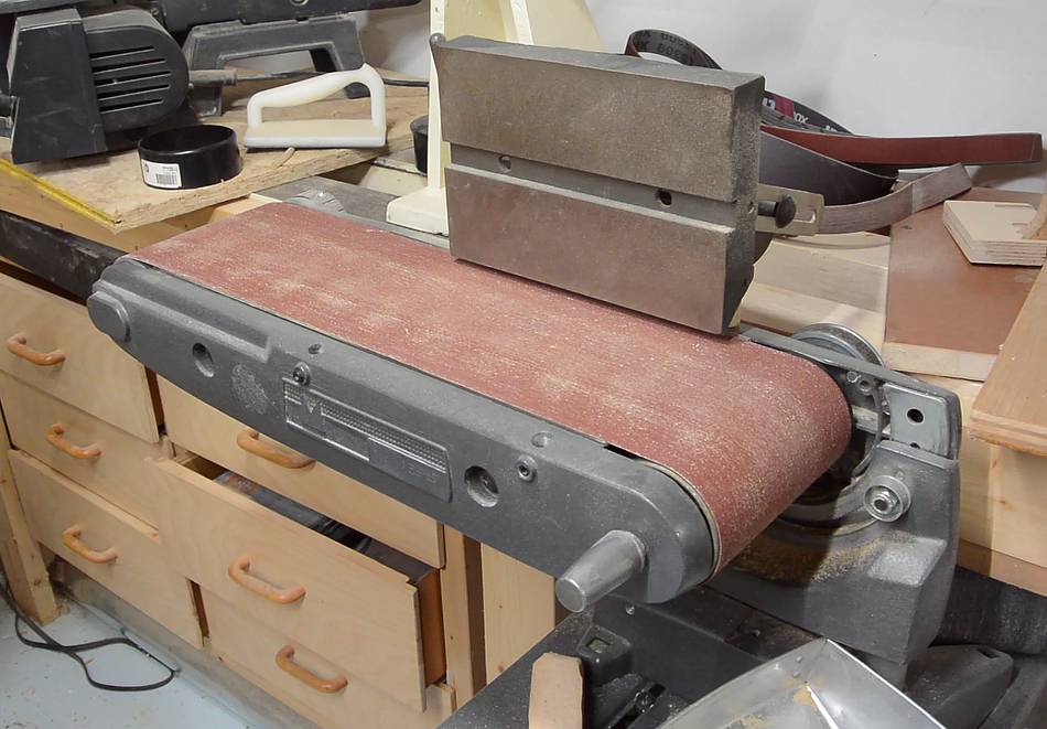
 I bought this 6x48" belt sander from a pawn shop in 1997. It's a Shopsmith
attachment, on a base, with its own motor.
I bought this 6x48" belt sander from a pawn shop in 1997. It's a Shopsmith
attachment, on a base, with its own motor.
I bought this 6x48" belt sander from a pawn shop in 1997. It's a Shopsmith
attachment, on a base, with its own motor.
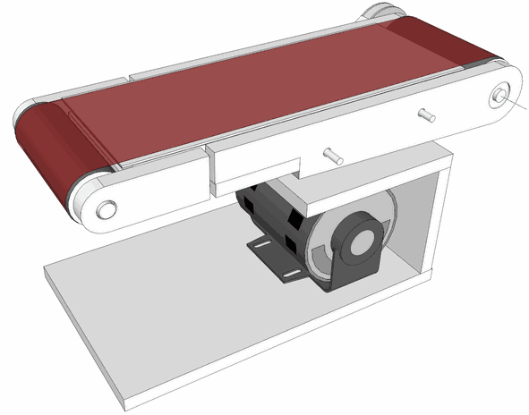 I had been meaning to replace it with a homemade belt sander for some time,
not out of necessity, more as a challenge. I came up with a design in
2012, but never got around to building it until now.
I had been meaning to replace it with a homemade belt sander for some time,
not out of necessity, more as a challenge. I came up with a design in
2012, but never got around to building it until now.
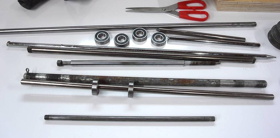 Going through my collection of shafting and bearings, I decided to use some
12 mm shaft for the main shaft, mainly because I already had some bearings that fit
it precisely. I decided to use some cheap 3/8" steel rod for the idler roller's
shaft, the same stuff I used for my
jointer parallelogram mechanism
Going through my collection of shafting and bearings, I decided to use some
12 mm shaft for the main shaft, mainly because I already had some bearings that fit
it precisely. I decided to use some cheap 3/8" steel rod for the idler roller's
shaft, the same stuff I used for my
jointer parallelogram mechanism
 The main roller on my existing belt sander is coated in rubber. I figure that
was a good idea, especially because on my
strip sander the belt can slip if I don't have enough tension.
The main roller on my existing belt sander is coated in rubber. I figure that
was a good idea, especially because on my
strip sander the belt can slip if I don't have enough tension.
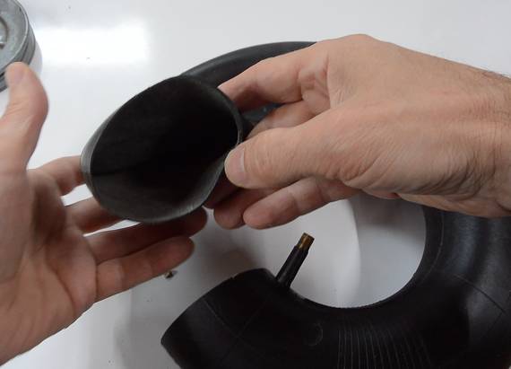
I bought some inner tube that I wanted to cut into strips to line the roller with, but when I cut it open I realized the rubber was thicker on the inside of the donut, so I couldn't use it.
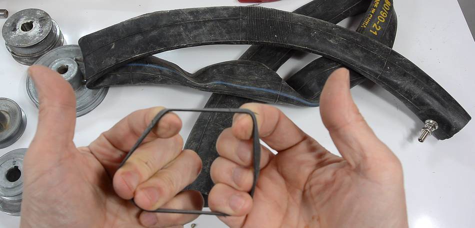 But I had a 2" bicycle inner tube, and that rubber could be streteched
quite a bit, so maybe I could use that.
But I had a 2" bicycle inner tube, and that rubber could be streteched
quite a bit, so maybe I could use that.
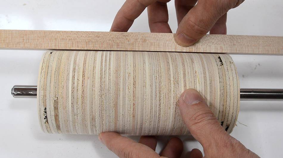
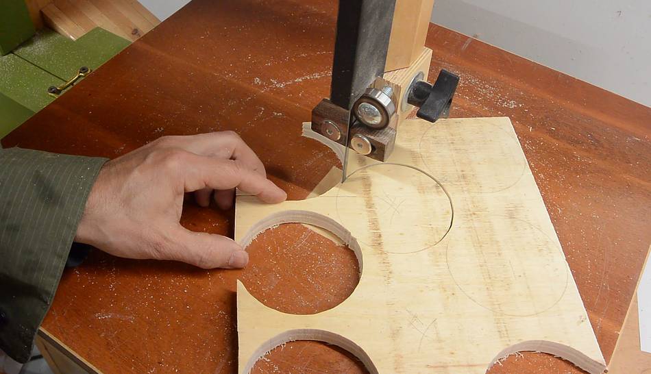 The main drive drum is made out of layers of plywood, which I cut out
on the bandsaw. My homemade bandsaw,
of course.
The main drive drum is made out of layers of plywood, which I cut out
on the bandsaw. My homemade bandsaw,
of course.
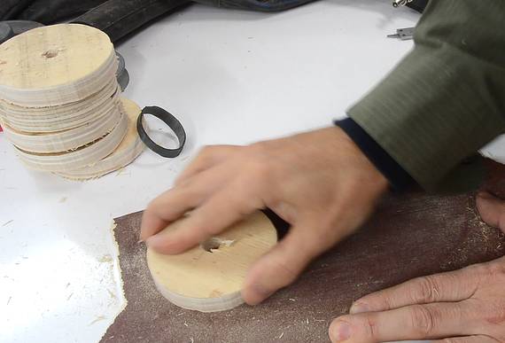 Afterwards I sanded all the layers to de-burr them, flatten them and expose
a fresh surface for better glue adhesion.
Afterwards I sanded all the layers to de-burr them, flatten them and expose
a fresh surface for better glue adhesion.
The photos shows doing this by hand, but in reality, I just used my existing belt sander to do most of them.
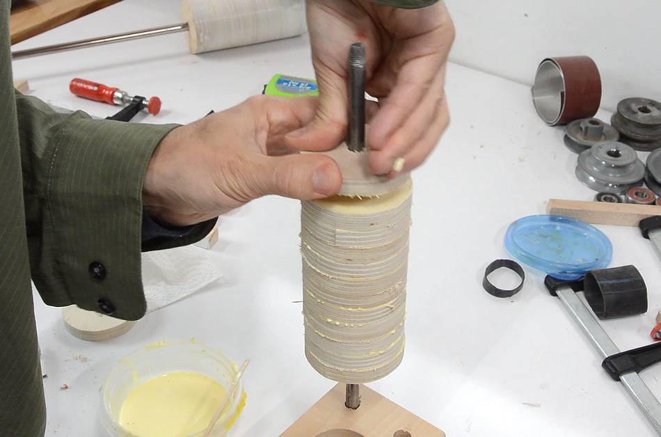
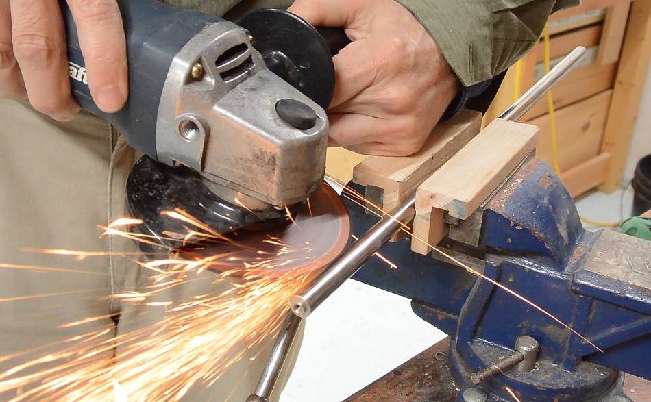 I used an angle grinder to cut a keyway in the shaft so I could later lock
the disk to it better.
I used an angle grinder to cut a keyway in the shaft so I could later lock
the disk to it better.
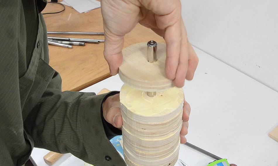
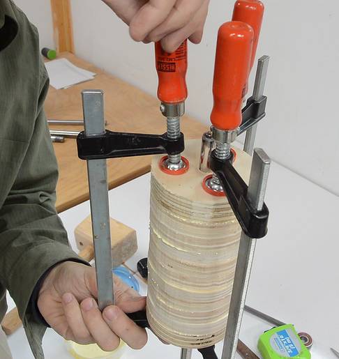 Then gluing the plywood layers together on the shaft.
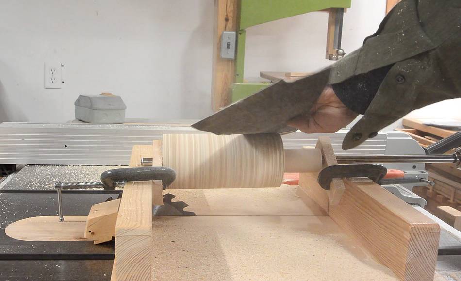
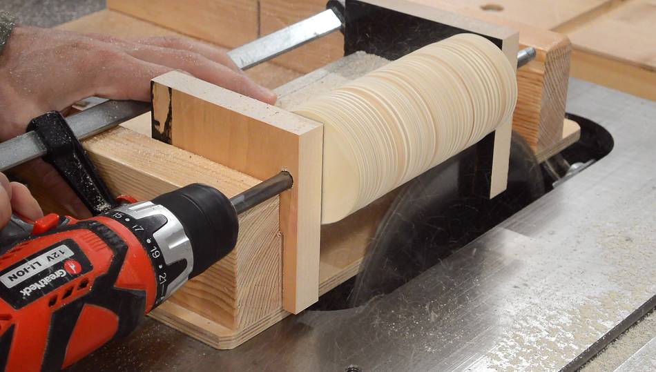
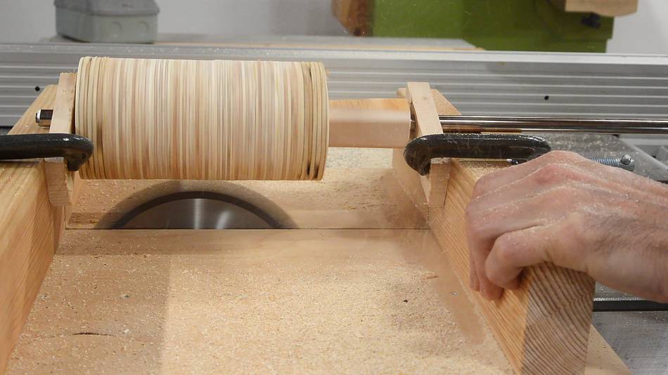 I turned and rounded the drum by mounting it above my
small table saw sled and
spinning it with a drill while slowly pushing it over the blade.
I turned and rounded the drum by mounting it above my
small table saw sled and
spinning it with a drill while slowly pushing it over the blade.
 Then more sanding, again by spinning it with the drill.
 It took quite a bit of tweaking to get the shape I wanted for the drum.
The drum is slightly bulged in the middle like a barrel
(crowned is the proper term). This will help
track the belt in the center.
I shaped that crown by mounting one side slightly
higher on the table saw sled to cut the cylinder into a cone shape, then
mounting the other side higher to cut a cone from the other end as well.
But in the end, it took several tries to get it right, and the drum ended
up a few millimeters smaller than I was aiming for.
It took quite a bit of tweaking to get the shape I wanted for the drum.
The drum is slightly bulged in the middle like a barrel
(crowned is the proper term). This will help
track the belt in the center.
I shaped that crown by mounting one side slightly
higher on the table saw sled to cut the cylinder into a cone shape, then
mounting the other side higher to cut a cone from the other end as well.
But in the end, it took several tries to get it right, and the drum ended
up a few millimeters smaller than I was aiming for.
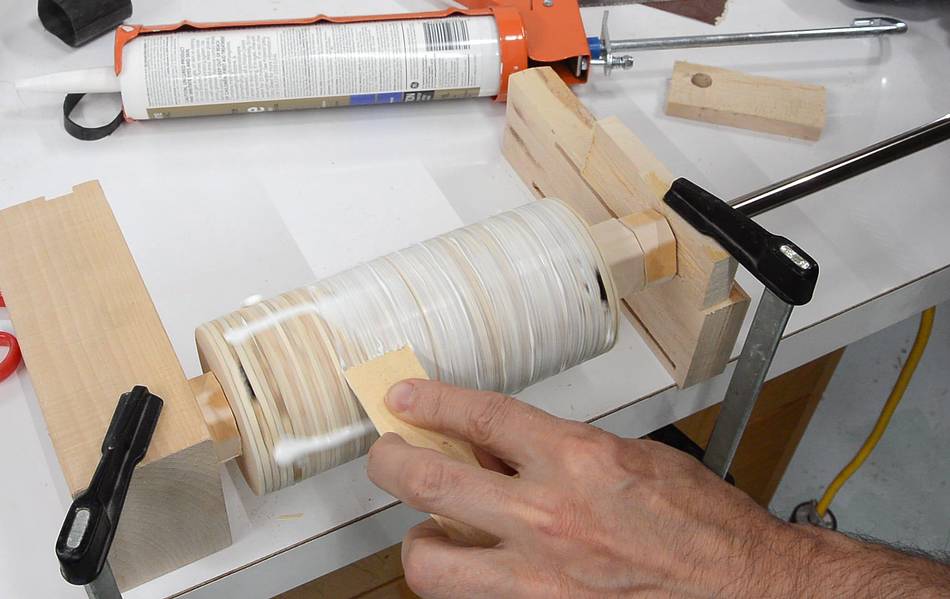 Trying to stretch even a 3 cm long section of inner tube onto the drum
was too difficult. So instead, I coated the drum in caulking.
I got this idea from John Heisz in his
quick and dirty bandsaw
mill build video.
Trying to stretch even a 3 cm long section of inner tube onto the drum
was too difficult. So instead, I coated the drum in caulking.
I got this idea from John Heisz in his
quick and dirty bandsaw
mill build video.
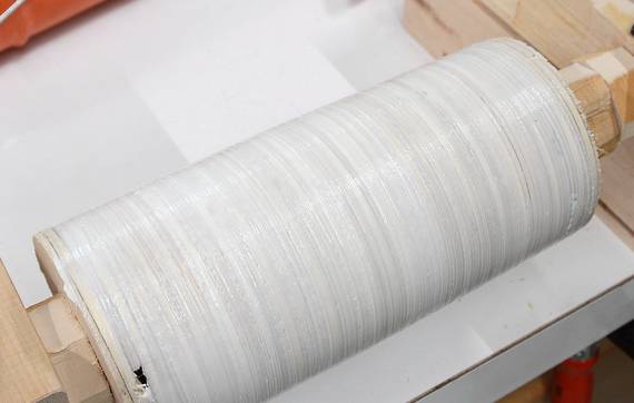 Using a piece of wood to spread the caulking while slowly spinning it with
a drill made for a nice and even coat.
Using a piece of wood to spread the caulking while slowly spinning it with
a drill made for a nice and even coat.
 I used pretty much the same method to make the idler roller, except that the
idler roller has a diameter of 6 cm instead of 8 cm and runs on a 3/8" (9.5 mm)
shaft instead of a 12 mm shaft.
I used pretty much the same method to make the idler roller, except that the
idler roller has a diameter of 6 cm instead of 8 cm and runs on a 3/8" (9.5 mm)
shaft instead of a 12 mm shaft.
 I had to mount this drum on the side of my table saw sled to get closer to
the blade to mill the smaller diameter.
I had to mount this drum on the side of my table saw sled to get closer to
the blade to mill the smaller diameter.
I also milled this one to be a straight cylinder (no crown). Belt sanders tend to have just one of the drums crowned. I read somewhere that some have found that this works best for a 6x48" belt sander, though I didn't experiment with this myself.
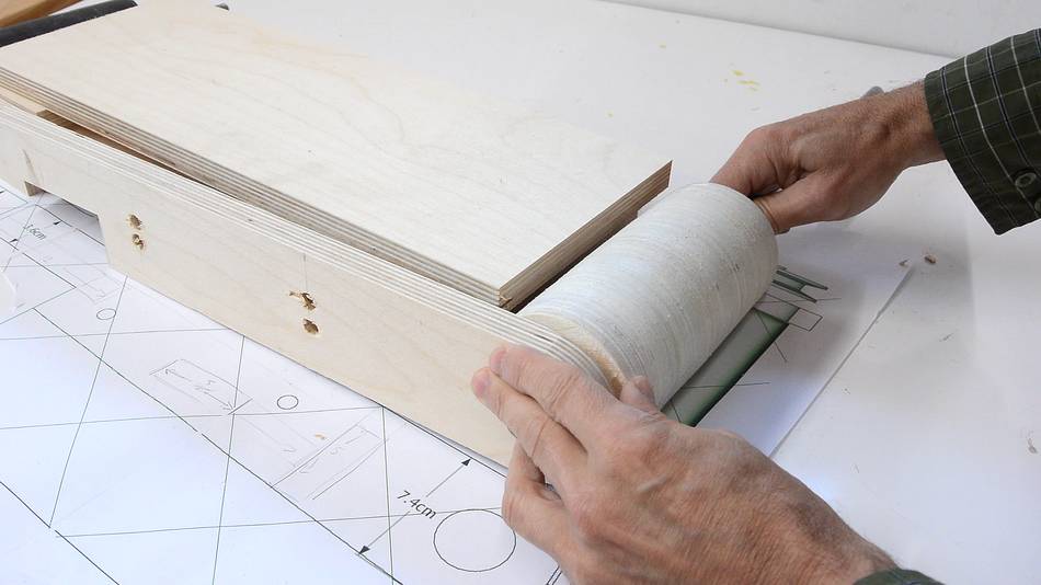
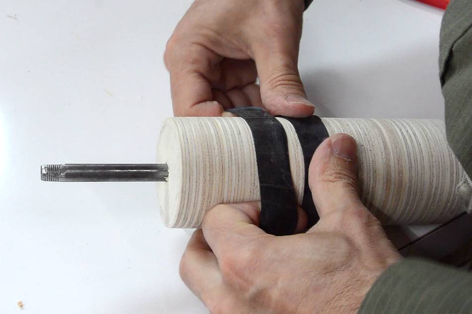 With the smaller 6 cm diameter of the idler drum, I was able to stretch pieces
of inner tube onto it in 2-3 cm wide sections.
With the smaller 6 cm diameter of the idler drum, I was able to stretch pieces
of inner tube onto it in 2-3 cm wide sections.
 I trimmed the last section flush on the end with a pair of scissors.
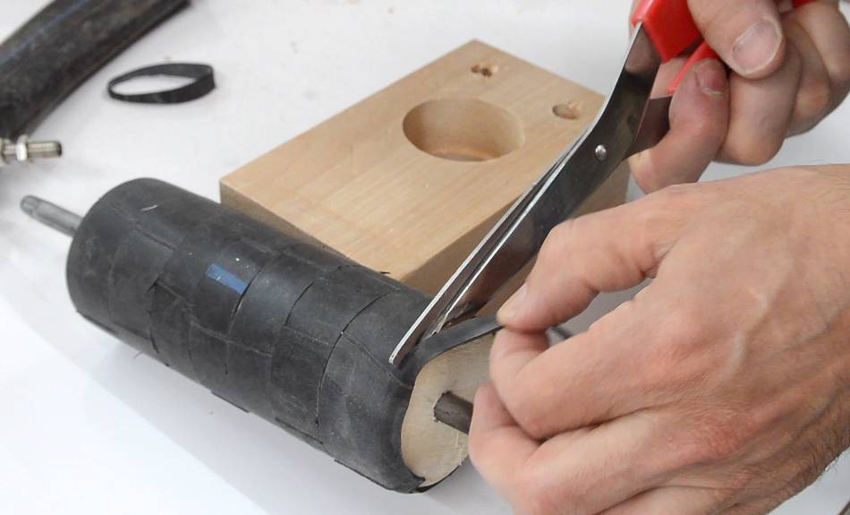
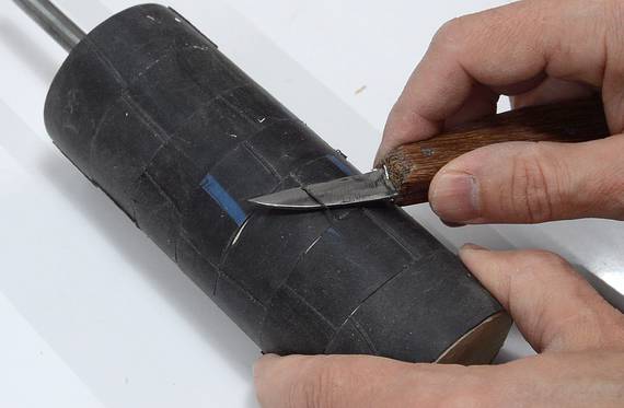 The inner tube also had some ridges from seams from the mold. I shaved these off
with a sharp knife (my homemade knife).
The inner tube also had some ridges from seams from the mold. I shaved these off
with a sharp knife (my homemade knife).
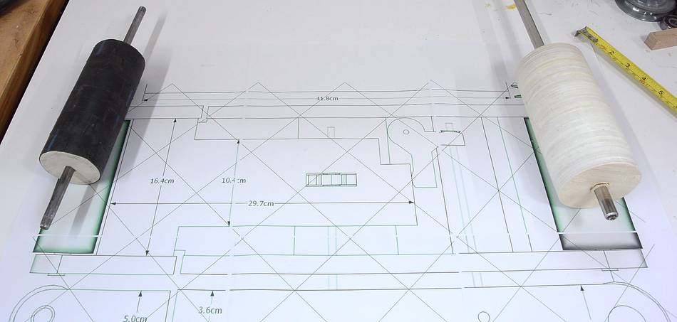 With the rollers made, I printed out 1:1 top and side views from my
SketchUp
CAD model using my BigPrint program.
The printout covered 8 sheets of regular letter (8.5x11", similar to A4) paper.
With the rollers made, I printed out 1:1 top and side views from my
SketchUp
CAD model using my BigPrint program.
The printout covered 8 sheets of regular letter (8.5x11", similar to A4) paper.
 Now it's time to start cutting up some of the fancy Baltic birch plywood.
It's expensive plywood, and if you were to build cabinets with it, the costs could add up quickly. But for a machine like this, I only end up using about $10 worth of the stuff.
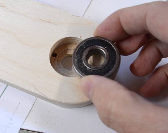
 The bearings I'm using have a 32 mm outside diameter. It turns out, this size
makes for a tight fit in the hole from my 1.25 inch Forstner bit (1.25 inches
is 31.75 mm, so I guess the drill drills slightly oversized).
The bearings I'm using have a 32 mm outside diameter. It turns out, this size
makes for a tight fit in the hole from my 1.25 inch Forstner bit (1.25 inches
is 31.75 mm, so I guess the drill drills slightly oversized).
I had the foresight to chisel two gaps next to the hole to pop the bearing back out with two screwdrivers after pressing it in the hole.
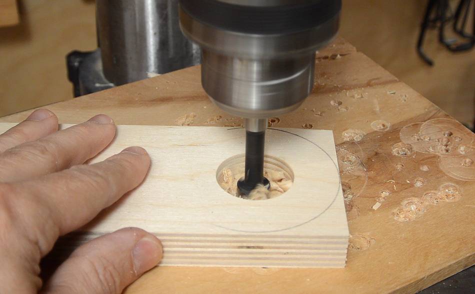 I then used my 1 1/4" drill to drill the bearing holes, then a smaller hole in
the middle for the shaft to pass through.
I then used my 1 1/4" drill to drill the bearing holes, then a smaller hole in
the middle for the shaft to pass through.
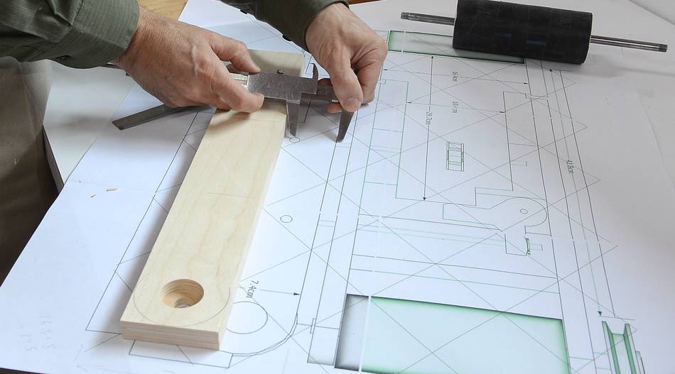
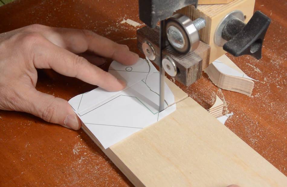
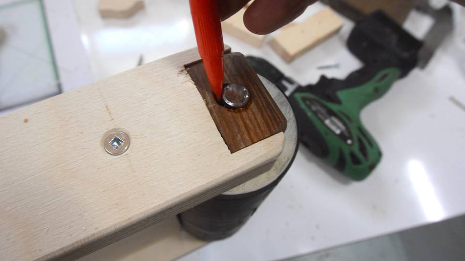
 Here I'm transferring the hole locations for the side part from the 1:1 drawing
to the piece of wood.
Here I'm transferring the hole locations for the side part from the 1:1 drawing
to the piece of wood.
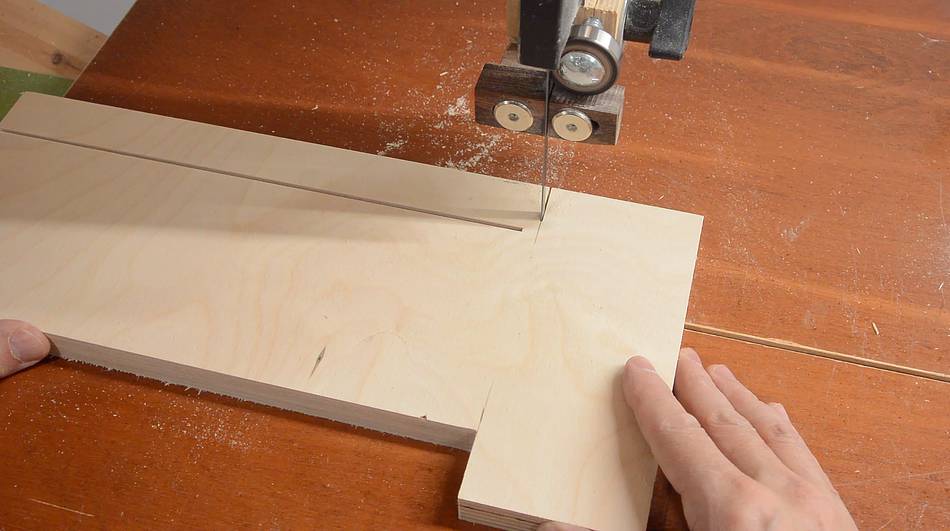
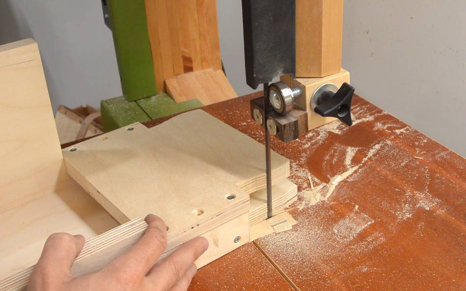
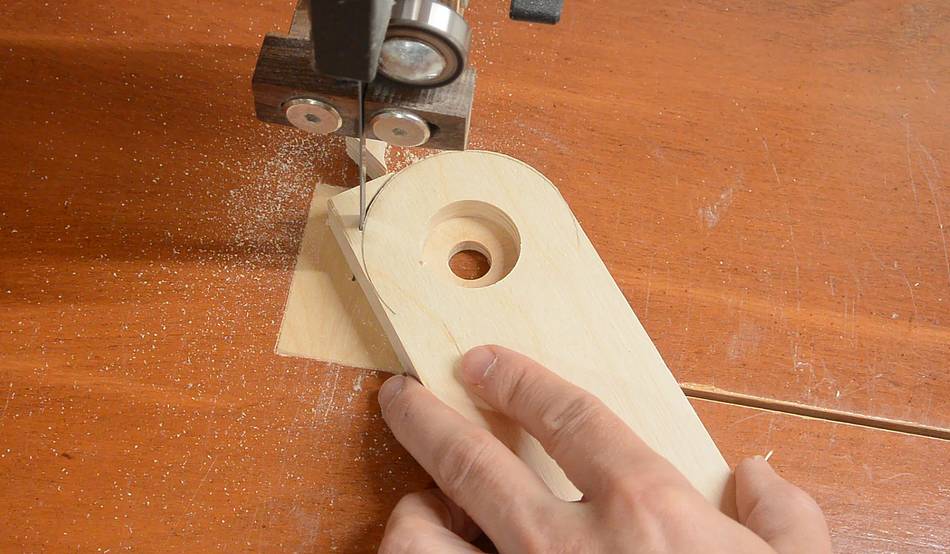 Cutting the ends of the front side round. They need to be round, otherwise, it would be
impossible to get the belt on and off.
Cutting the ends of the front side round. They need to be round, otherwise, it would be
impossible to get the belt on and off.
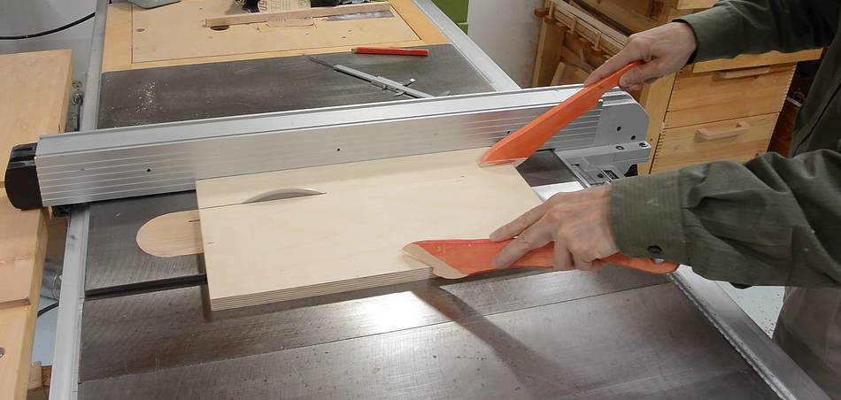
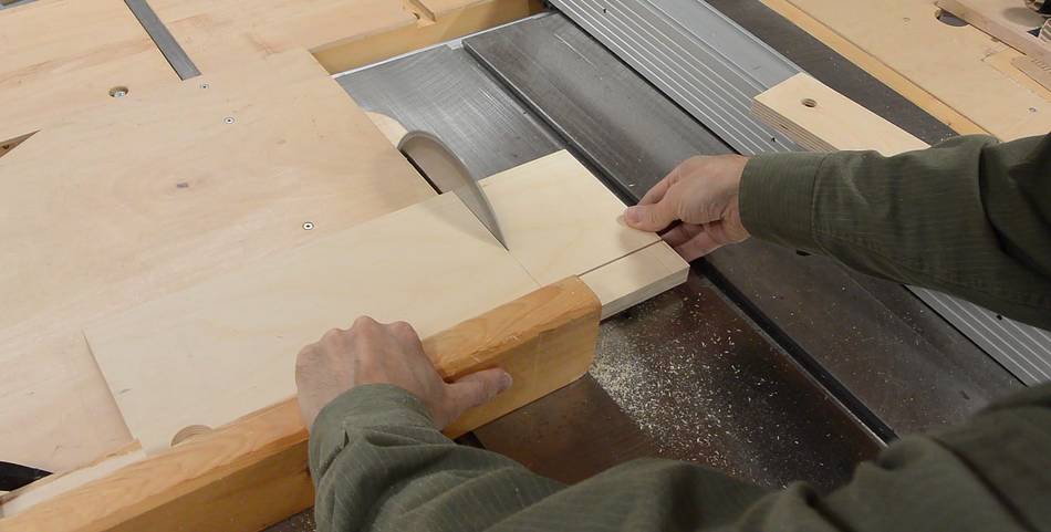 Cutting some of the other parts. Most of the cuts that are parallel or
perpendicular to the edges are made on the table saw for better accuracy.
Cutting some of the other parts. Most of the cuts that are parallel or
perpendicular to the edges are made on the table saw for better accuracy.
 Though some of the shorter ones I just did on the bandsaw.
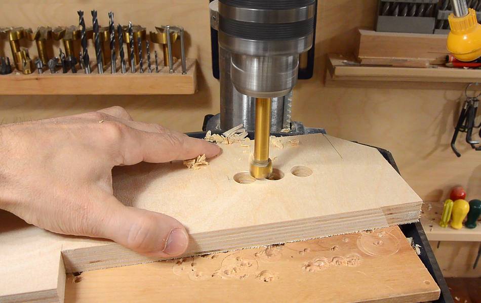
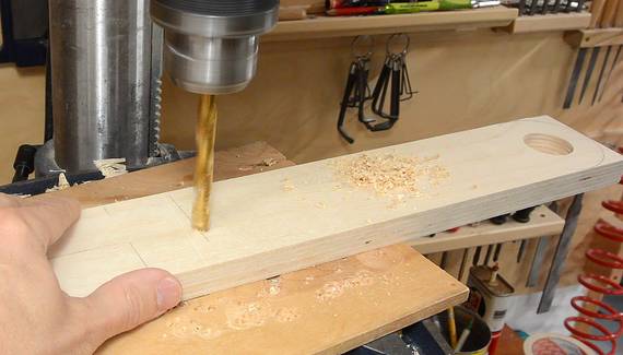
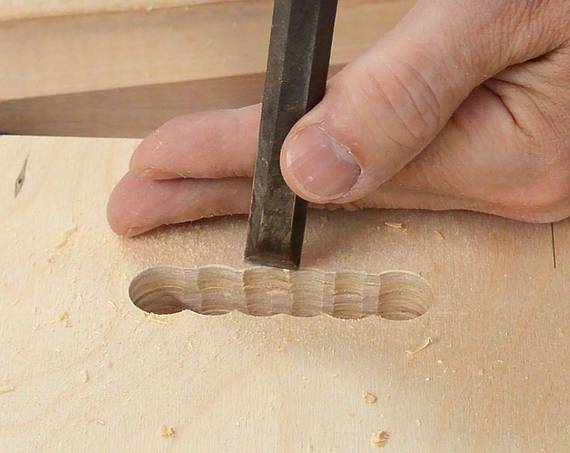 The part that holds the idler roller needs a slot in it for tracking
adjustment. I drilled a series of overlapping holes on the drill
press, then cleaned it up with a chisel.
The part that holds the idler roller needs a slot in it for tracking
adjustment. I drilled a series of overlapping holes on the drill
press, then cleaned it up with a chisel.
 This funny shaped part will be for applying tension.
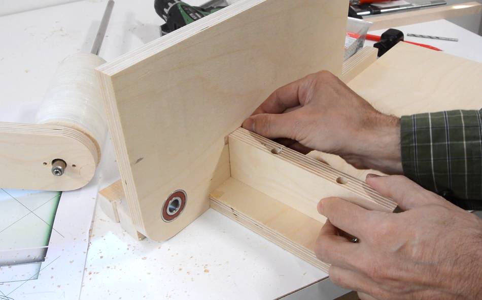
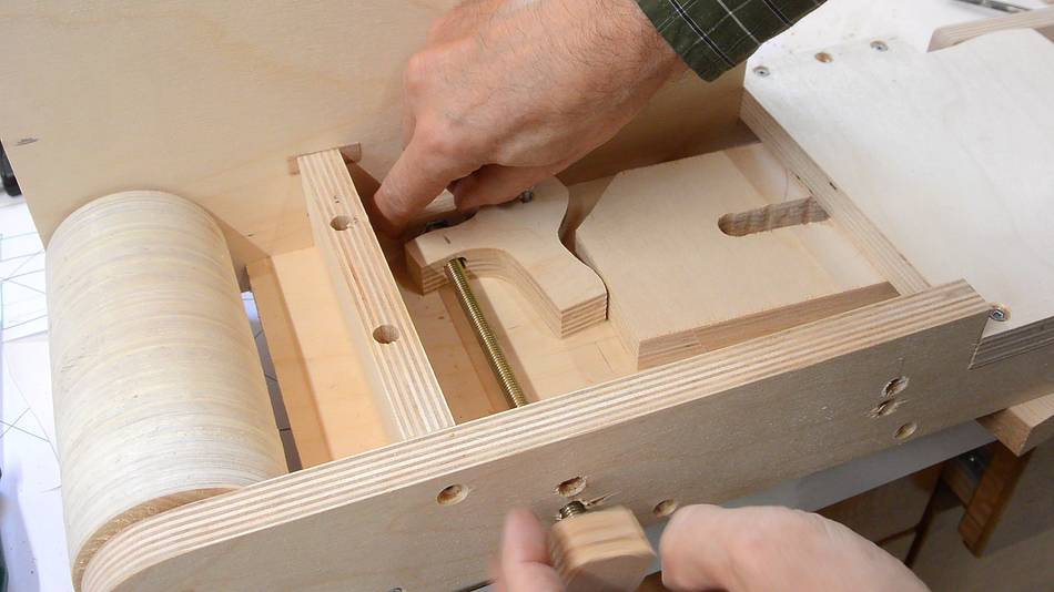
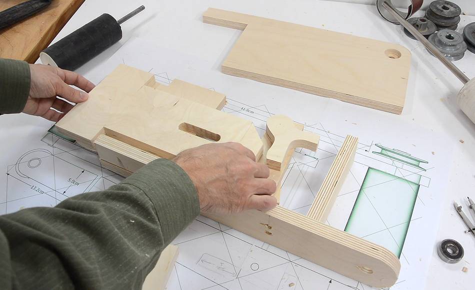 Here's how the parts will fit together. The part I'm holding will have the idler
roller attached to it, with the funny shaped part I just cut pushing it to
the left to apply belt tension.
Here's how the parts will fit together. The part I'm holding will have the idler
roller attached to it, with the funny shaped part I just cut pushing it to
the left to apply belt tension.
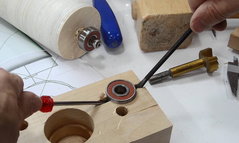
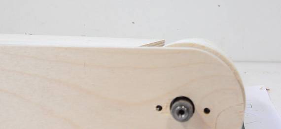
 Pressing one of the main bearings into its mount. Before pressing that in,
I drilled two extra holes all the way through which will enable me to push
the bearing back out if I need to later. You can see one of these holes
in the picture at right.
Pressing one of the main bearings into its mount. Before pressing that in,
I drilled two extra holes all the way through which will enable me to push
the bearing back out if I need to later. You can see one of these holes
in the picture at right.
 Drive roller mounted. The drive roller's top surface is 3 mm above the part
that it mounts to.
Drive roller mounted. The drive roller's top surface is 3 mm above the part
that it mounts to.
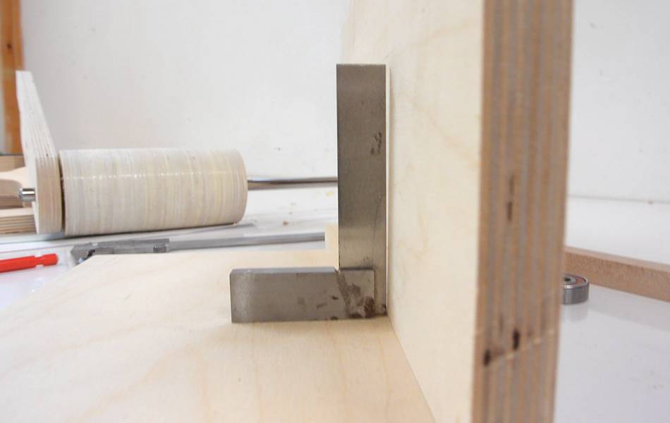 Getting ready to mount the piece of plywood that will be the behind the sanding
belt to the sides. But I discovered the edges were slightly bevelled, so they
wouldn't join at a right angle.
Getting ready to mount the piece of plywood that will be the behind the sanding
belt to the sides. But I discovered the edges were slightly bevelled, so they
wouldn't join at a right angle.
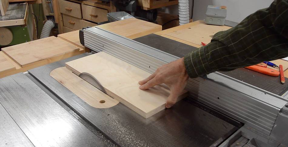 So I cut a fraction of a millimeter off the side of it on the table saw to bring
that edge into square. I set the fence on the saw by placing the piece to the
right of the saw blade, then pressing the fence against it. Then pulling the piece
out, starting the saw, and pushing it through to cut about 0.1 mm off the workpiece.
So I cut a fraction of a millimeter off the side of it on the table saw to bring
that edge into square. I set the fence on the saw by placing the piece to the
right of the saw blade, then pressing the fence against it. Then pulling the piece
out, starting the saw, and pushing it through to cut about 0.1 mm off the workpiece.
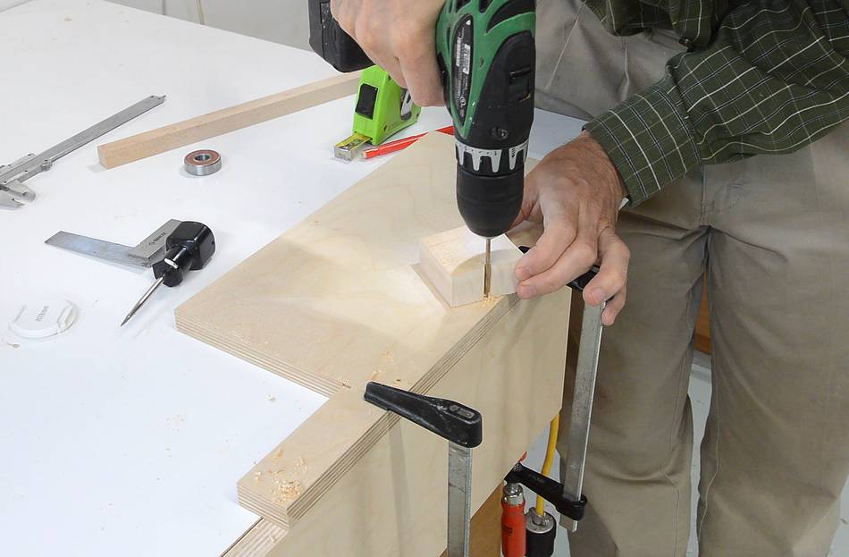
 With both pieces clamped together, I drilled four pilot holes in both parts, followed
by a slightly larger shank hole, followed by countersinks for the screw heads.
With both pieces clamped together, I drilled four pilot holes in both parts, followed
by a slightly larger shank hole, followed by countersinks for the screw heads.
There are of course drill bits that will do this in one go, but I don't have one, and with just a few holes, it would hardly be worth the effort to adjust one of these (and then it still might not have the right combination of shank and pilot hole diameters that I want)
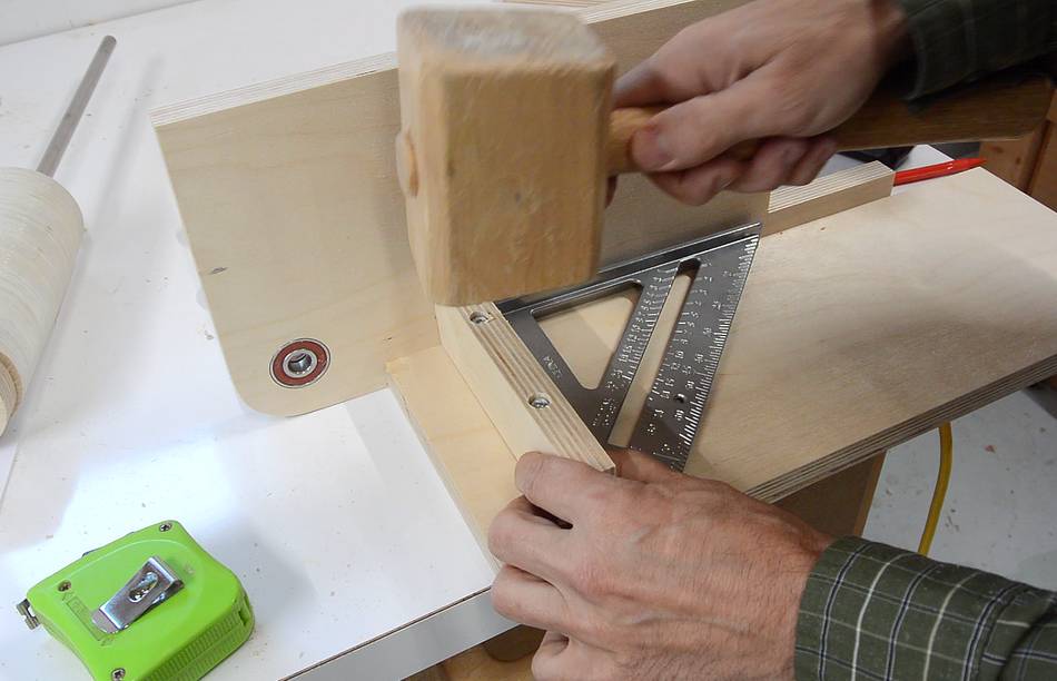 Another crossbrace goes here to help hold the parts square. I have the screws already
in it, and I'm tapping it against the wood to get the tips of the screws to mark
where the pilot holes need to go.
Another crossbrace goes here to help hold the parts square. I have the screws already
in it, and I'm tapping it against the wood to get the tips of the screws to mark
where the pilot holes need to go.
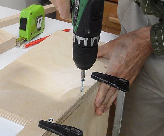
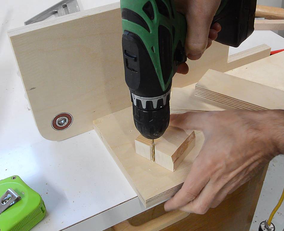 Then drilling the pilot holes, with a block of wood to control the depth,
and screwing it on.
Then drilling the pilot holes, with a block of wood to control the depth,
and screwing it on.
 With the piece screwed on, it's off to the side by a fraction of a millimeter.
So I had to shim it on one side, and cut a fraction of a millimeter off on
the other end.
With the piece screwed on, it's off to the side by a fraction of a millimeter.
So I had to shim it on one side, and cut a fraction of a millimeter off on
the other end.
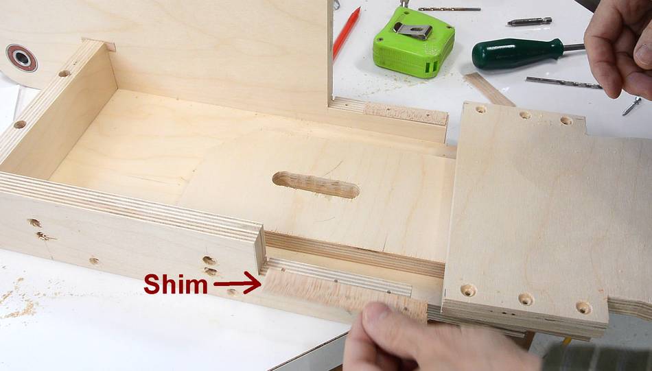 The part that the idle roller mounts to (with the slot in it) slides between
two layers of plywood, but the way this turned out, it would have been
a tight squeeze, so I had to make some shims to add more space.
The part that the idle roller mounts to (with the slot in it) slides between
two layers of plywood, but the way this turned out, it would have been
a tight squeeze, so I had to make some shims to add more space.
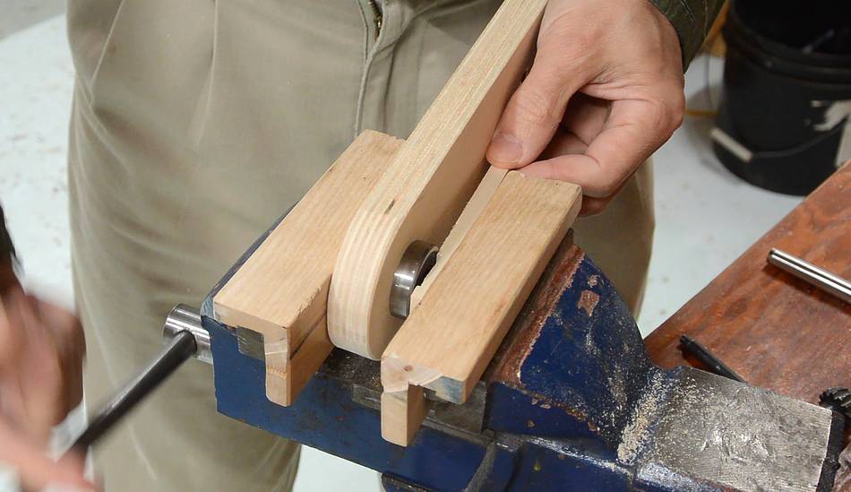
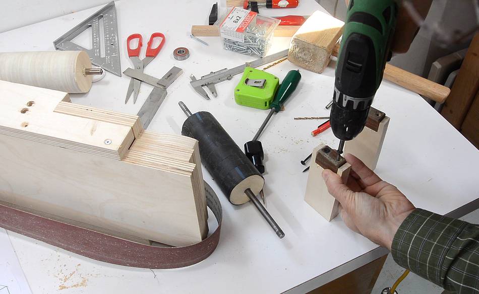 I'm using wooden bearings for the idler roller, using some small blocks of
lignum vitae, which I'm attaching to the bearing mounts here.
I'm using wooden bearings for the idler roller, using some small blocks of
lignum vitae, which I'm attaching to the bearing mounts here.
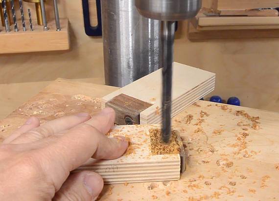 Once mounted, I drilled a 3/8" hole in the blocks.
 Due to some slight misalignment, the shaft turned a bit tight in the blocks.
To give them a bit more tolerance, I ran the drill in the holes while slightly
pivoting the block side to side. But the drill got caught and ripped
a substantial gash in part of the block. The shaft is still held securely
(the gash isn't all the way through). So I'll just leave it like this.
If it wears out, I can always replace the bearing blocks.
Due to some slight misalignment, the shaft turned a bit tight in the blocks.
To give them a bit more tolerance, I ran the drill in the holes while slightly
pivoting the block side to side. But the drill got caught and ripped
a substantial gash in part of the block. The shaft is still held securely
(the gash isn't all the way through). So I'll just leave it like this.
If it wears out, I can always replace the bearing blocks.
Update 2021: Five years on since I built it, thse bearing blocks are still fine, even the one with the gash.
 The top piece of plywood needs to be shaped in a way that the roller mount
on the end can pivot against it. So, without disassembling what I have so far,
I'm making the cut on the bandsaw.
The top piece of plywood needs to be shaped in a way that the roller mount
on the end can pivot against it. So, without disassembling what I have so far,
I'm making the cut on the bandsaw.
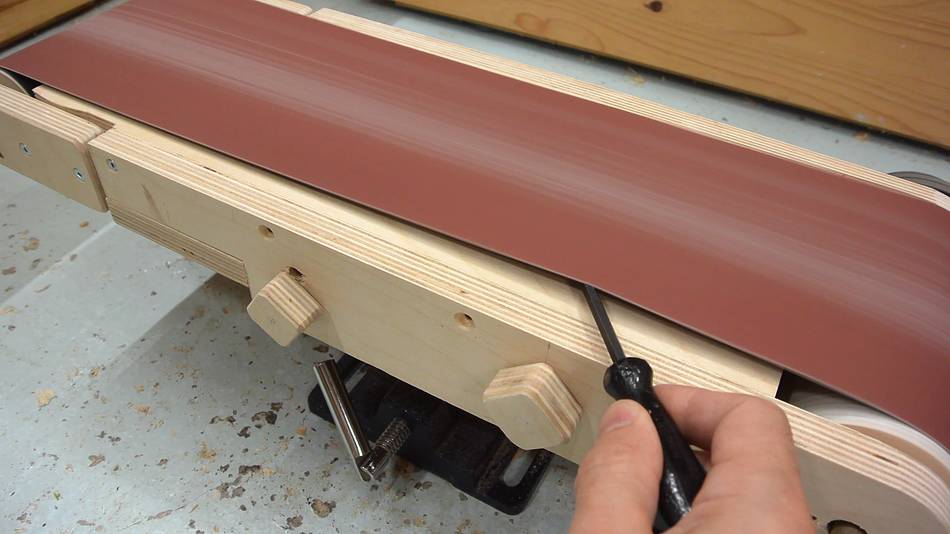
 Now mounting the part that tensions the belt. It pivots on a screw, and the
short arm is pulled with a threaded rod. A nut goes on the end of the
threaded rod. I made a block of wood that this nut fits into to keep
it from spinning as the threaded rod is turned.
Now mounting the part that tensions the belt. It pivots on a screw, and the
short arm is pulled with a threaded rod. A nut goes on the end of the
threaded rod. I made a block of wood that this nut fits into to keep
it from spinning as the threaded rod is turned.
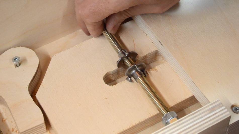 I had the idea of using two T-nuts in the slot to adjust the tracking.
The prongs of the T-nut, against the edge of the slot, prevents them from
turning with the shaft. But this turned out to be a bad idea - the prongs
get caught as the slot moves left and right when adjusting tension.
I had the idea of using two T-nuts in the slot to adjust the tracking.
The prongs of the T-nut, against the edge of the slot, prevents them from
turning with the shaft. But this turned out to be a bad idea - the prongs
get caught as the slot moves left and right when adjusting tension.
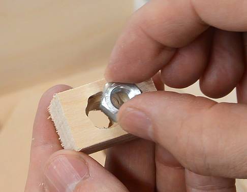
 So I made a little block of wood that holds just one T-nut that fits
into the slot. This block overhangs the slot on the other side to keep
it from tipping into the slot.
So I made a little block of wood that holds just one T-nut that fits
into the slot. This block overhangs the slot on the other side to keep
it from tipping into the slot.
This method of adjusting tracking worked, but it was difficult to adjust, so I ended up redoing how tracking and tension adjustments work later.
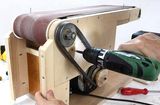
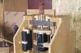
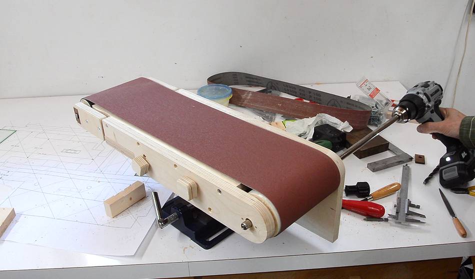 With what I have so far, it was time to try it out with a belt. Here
I'm, spinning it with a drill.
With what I have so far, it was time to try it out with a belt. Here
I'm, spinning it with a drill.
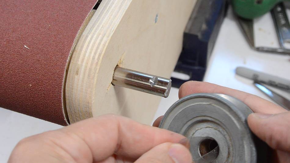 I have a 2.5" (73 mm) pulley with a 1/2" (12.7 mm) hole to mount on the
12 mm shaft. Using some plastic from a pop bottle made for a shim to snugly
fit on the shaft. The shim, being transparent, is hard to see in this photo.
I have a 2.5" (73 mm) pulley with a 1/2" (12.7 mm) hole to mount on the
12 mm shaft. Using some plastic from a pop bottle made for a shim to snugly
fit on the shaft. The shim, being transparent, is hard to see in this photo.
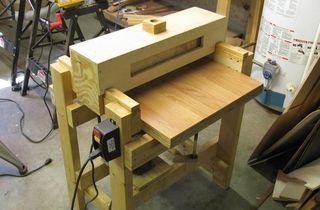
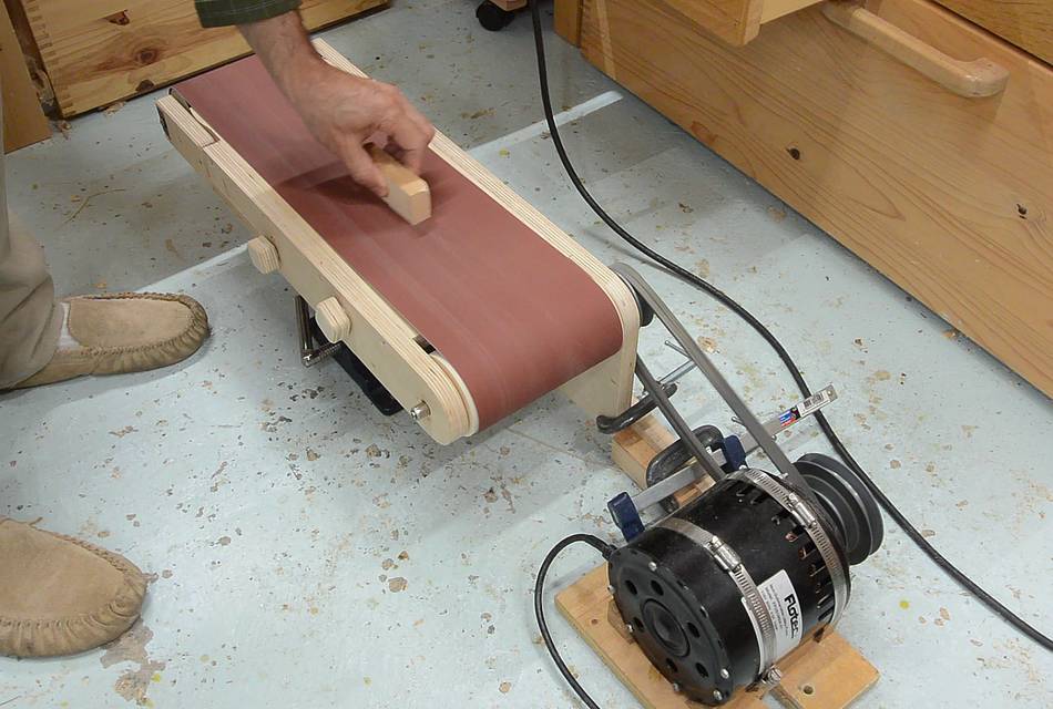 Now powering it with a 1/2 hp induction motor
and trying out the sander. It works!
Now powering it with a 1/2 hp induction motor
and trying out the sander. It works!
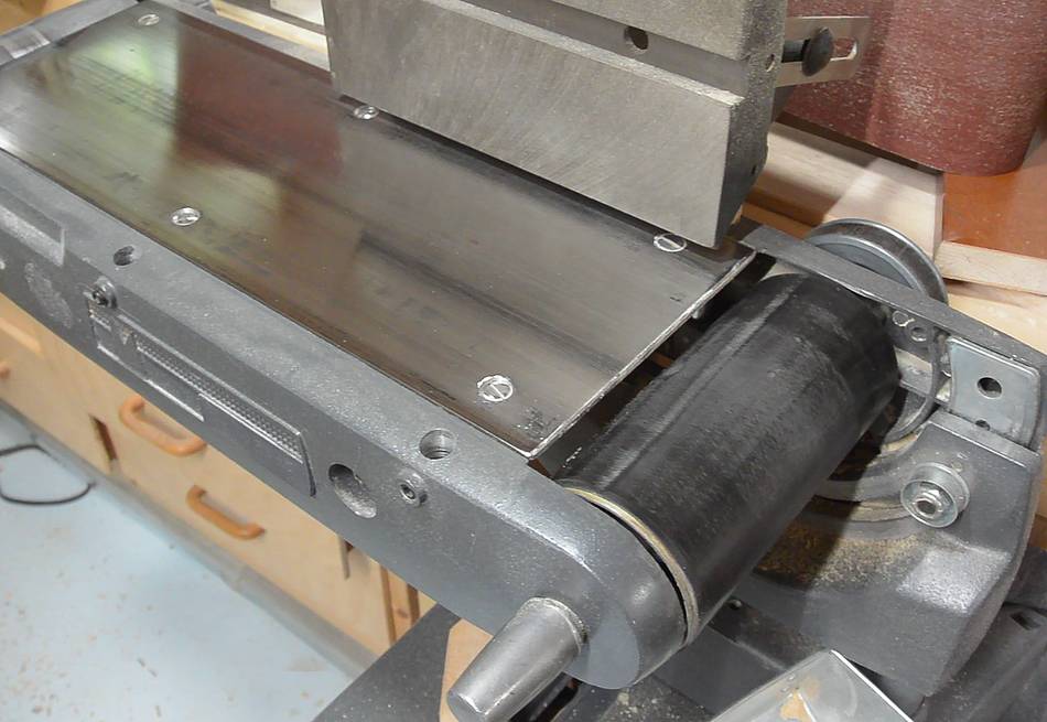
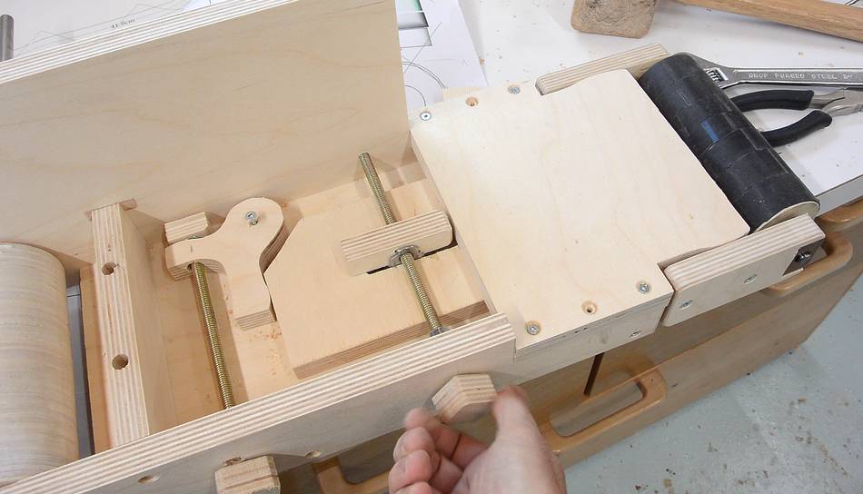
 But there is still a lot of work left to be done on the sander.
Not the least of which is to have some backer underneath the sanding belt.
But there is still a lot of work left to be done on the sander.
Not the least of which is to have some backer underneath the sanding belt.
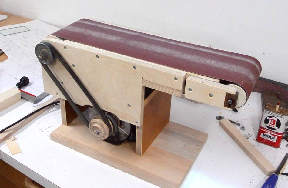 I also built a base to hold the sander unit and motor together.
But that's enough for now!
Belt sander build continued...
 Belt sander base, pulley and dust collection
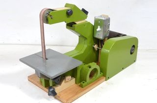 Strip sander
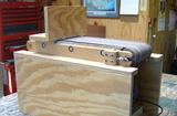
 More sanding machines