 Back in 2011, when I built the blower for my
first dust collector, I found my motor wasn't powerful enough for the
first impeller I built for it, but when I built one with backward curved vanes,
it was able to power that one.
Back in 2011, when I built the blower for my
first dust collector, I found my motor wasn't powerful enough for the
first impeller I built for it, but when I built one with backward curved vanes,
it was able to power that one.
Back in 2011, when I built the blower for my
first dust collector, I found my motor wasn't powerful enough for the
first impeller I built for it, but when I built one with backward curved vanes,
it was able to power that one.
So I was pretty sure backward curved fins are more efficient, especially because that's the design I always saw used in water pumps and vacuum cleaners. But I wanted to do some actual experiments to compare.
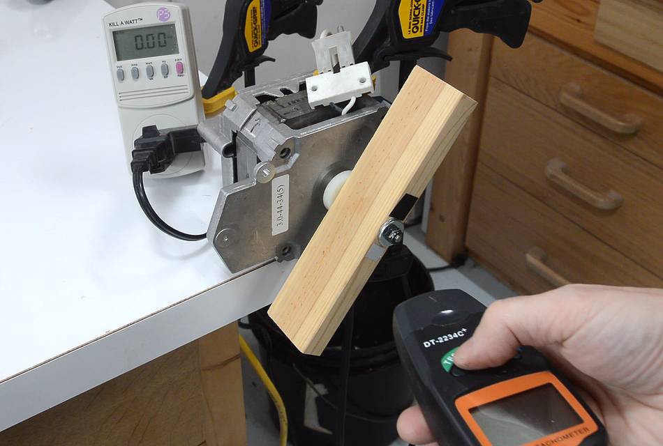
I picked up this dishwasher motor from the garbage, and I figured this was a good motor to use for some experiments. The motor is rated for 3150 RPM, 1.75 amps at 120 volts.
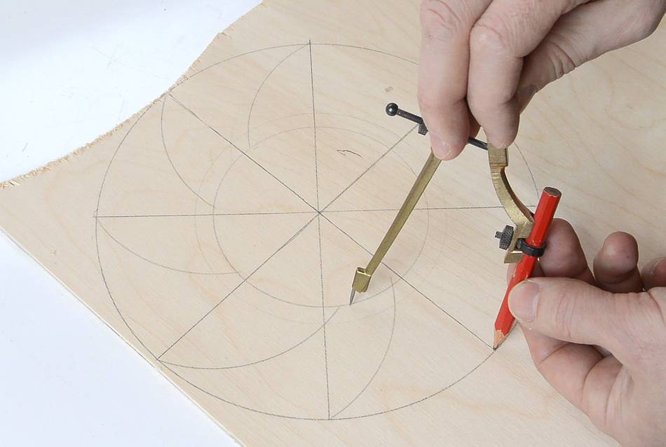
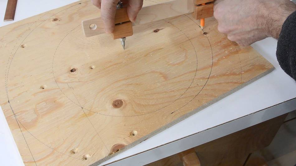
 I drew a layout for an 8-fin impeller on some plywood.
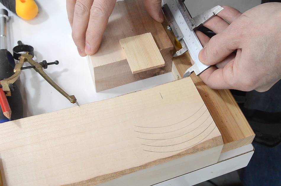
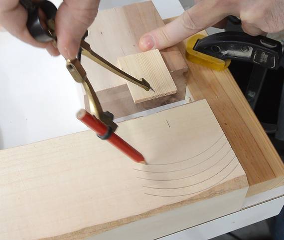 The curved vanes are cut from a solid piece of silver maple. I drew a series of equally
spaced arcs, controlling for the spacing using a set of callipers to move the center point
of the circles...
The curved vanes are cut from a solid piece of silver maple. I drew a series of equally
spaced arcs, controlling for the spacing using a set of callipers to move the center point
of the circles...
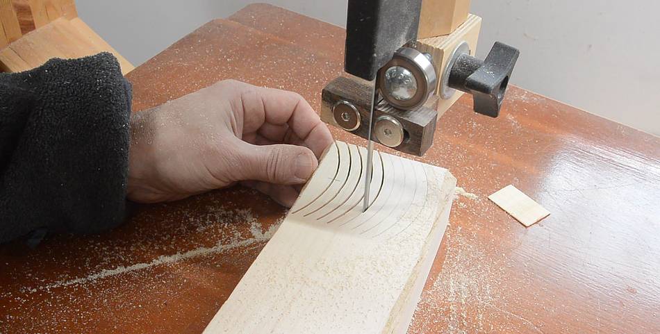
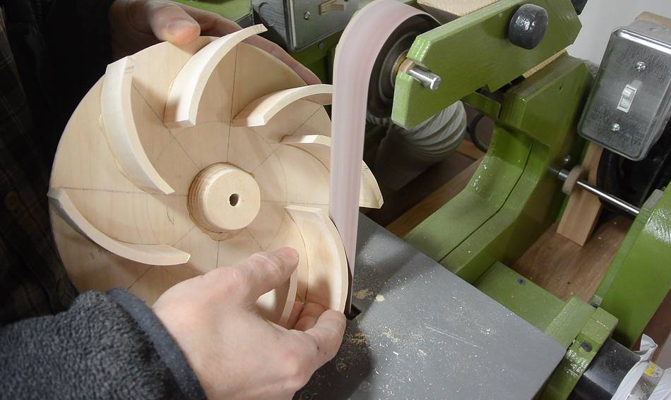
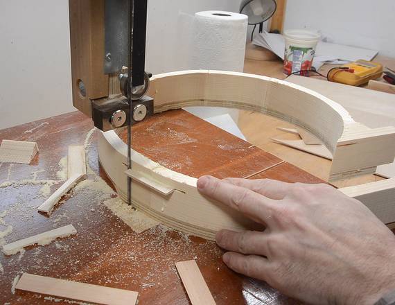
 ... then cutting the fins out on the bandsaw. I sanded the surfaces smooth on
my belt sander.
... then cutting the fins out on the bandsaw. I sanded the surfaces smooth on
my belt sander.
 I used the shank of a drill to help line up the hub of the rotor with the hole in
the rotor while the glue dried.
I used the shank of a drill to help line up the hub of the rotor with the hole in
the rotor while the glue dried.
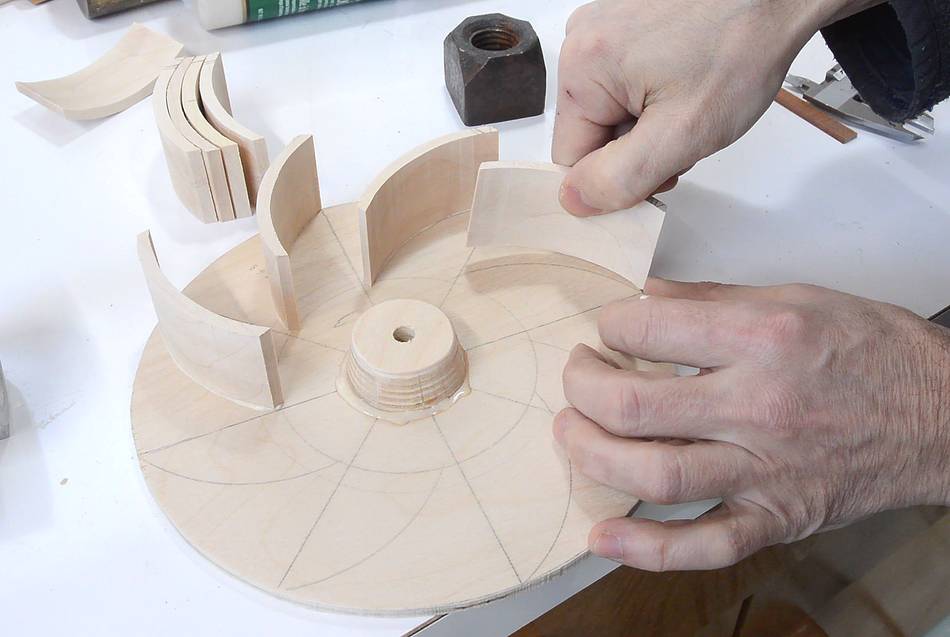
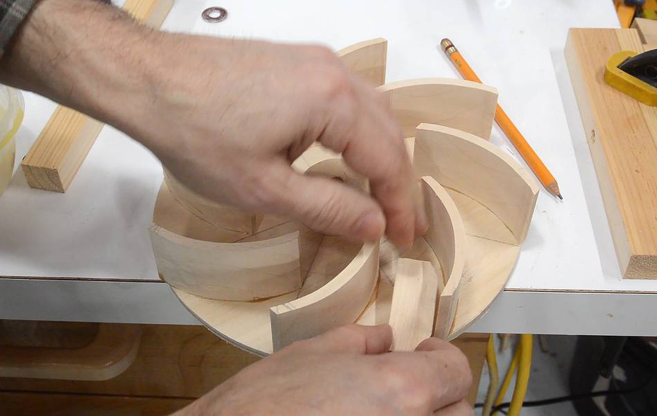
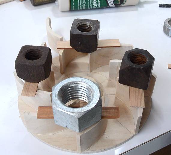 Then gluing on the fins. I gave the plywood a light sanding (figuring that should remove
any surface grime for better glue adhesion), then weighed the fins down while
the glue dried.
Then gluing on the fins. I gave the plywood a light sanding (figuring that should remove
any surface grime for better glue adhesion), then weighed the fins down while
the glue dried.
 I found the rotor was slightly out of balance. First I tried to balance it by
sanding some of the fins on the heavier side using my
strip sander.
I found the rotor was slightly out of balance. First I tried to balance it by
sanding some of the fins on the heavier side using my
strip sander.
 But I didn't want to move too much material so eventually glued a counterweight
on the light side.
But I didn't want to move too much material so eventually glued a counterweight
on the light side.
Though, once I reviewed the video, at some point I spun the rotor, and the aliasing from the camera made it very clear that two fins were glued slightly in the wrong place. I was able to pry these off again without too much damage, and once they were glued back on in the right place, the counterweight was largely unnecessary, so I chiselled most of it off.
If you look at the second photo in this article, you can see I drew one of the arcs out of place, and then I glued the fin where the arc was.
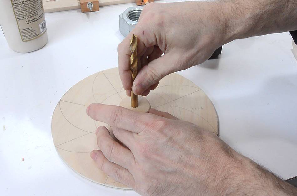
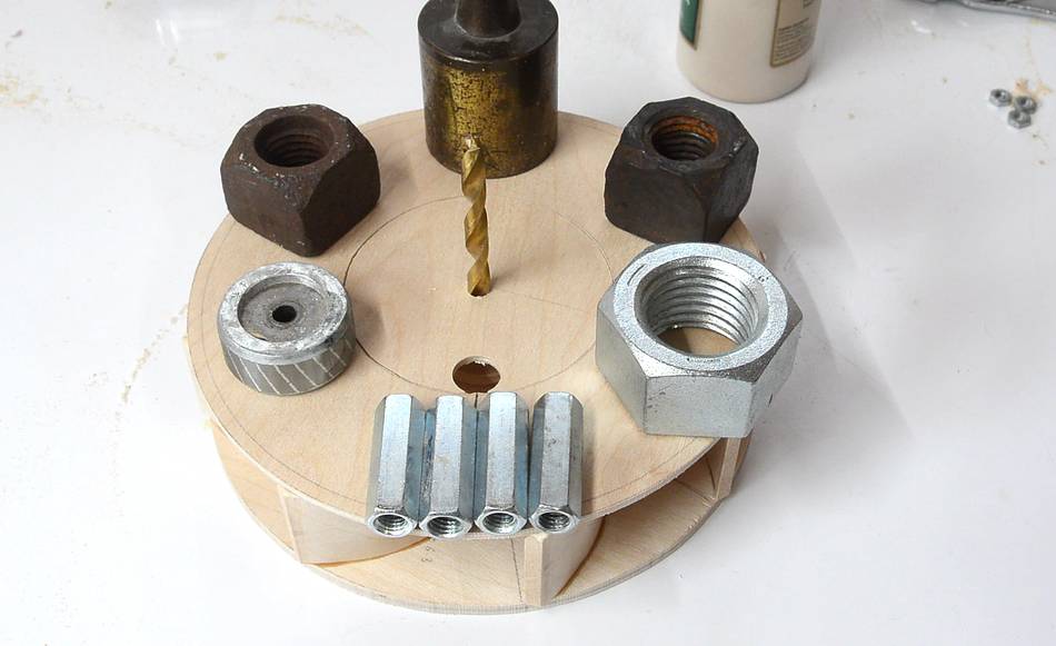
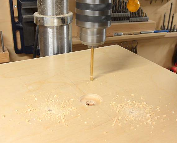
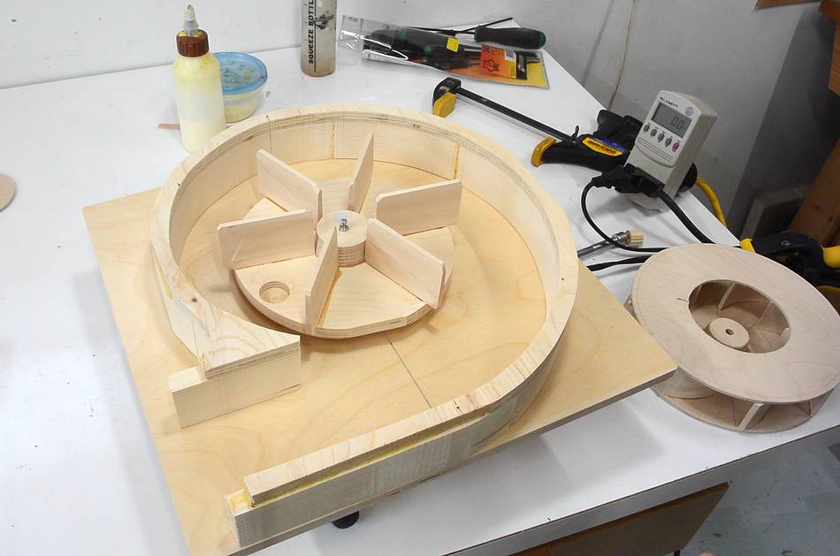
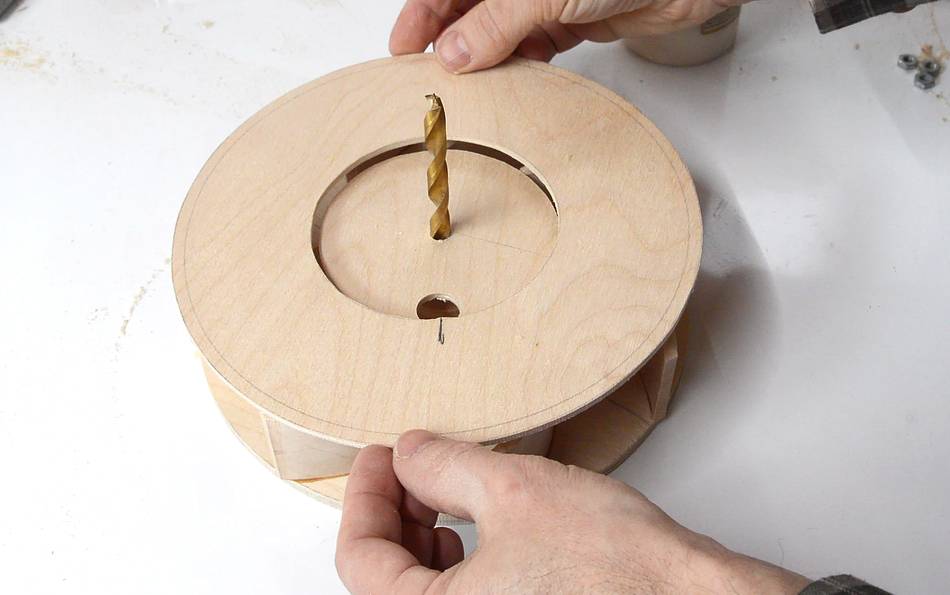 So far I built a total of four impellers of this overall design, and every time
I ended up getting the second disk (with the big hole) slightly off-center.
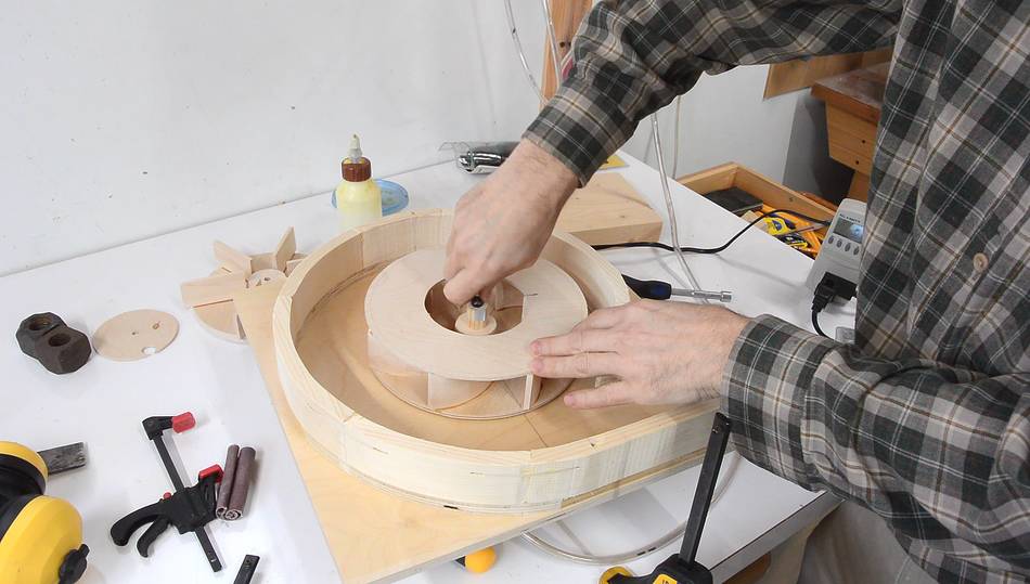
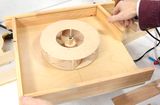
But this time I had the idea of putting the cut-out in the middle, with a
drill to hold it centered as a guide. I was able to position the second layer
much more precisely this way.
So far I built a total of four impellers of this overall design, and every time
I ended up getting the second disk (with the big hole) slightly off-center.
But this time I had the idea of putting the cut-out in the middle, with a
drill to hold it centered as a guide. I was able to position the second layer
much more precisely this way.
 Then weighing it down while the glue dried.
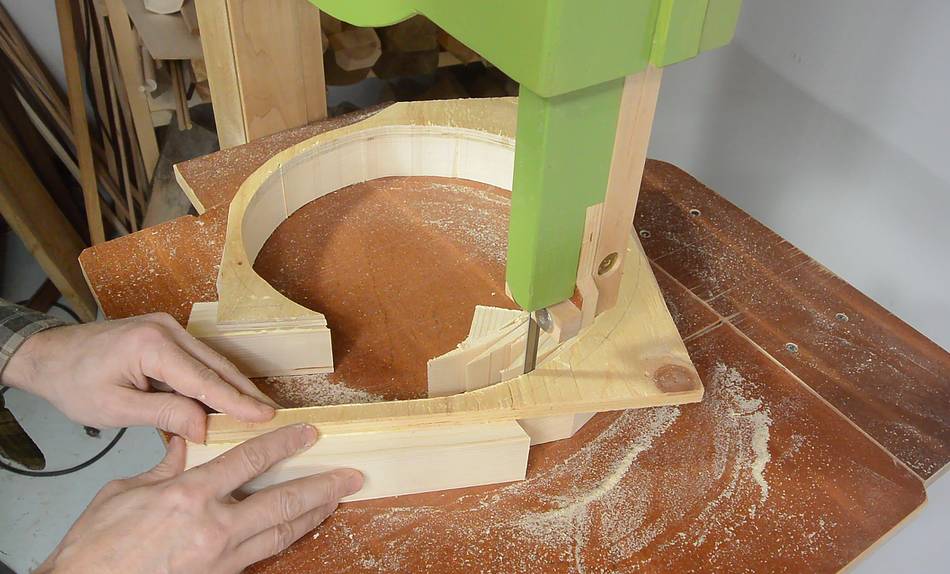
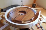
 I approximated a spiral for the housing using a series of four arcs drawn
using my beam compass
I approximated a spiral for the housing using a series of four arcs drawn
using my beam compass
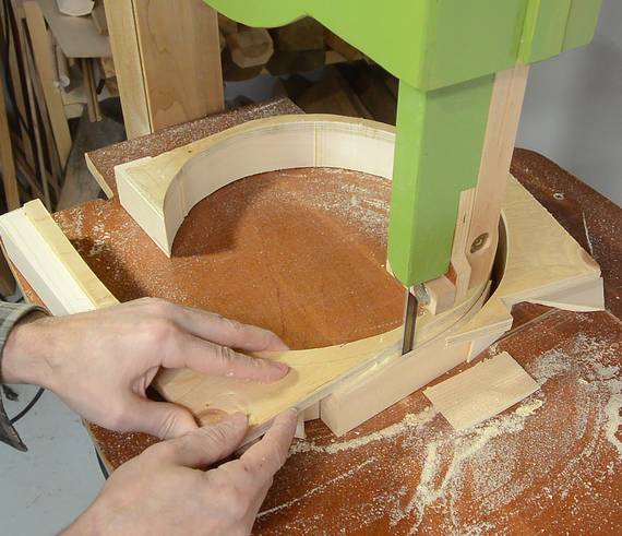
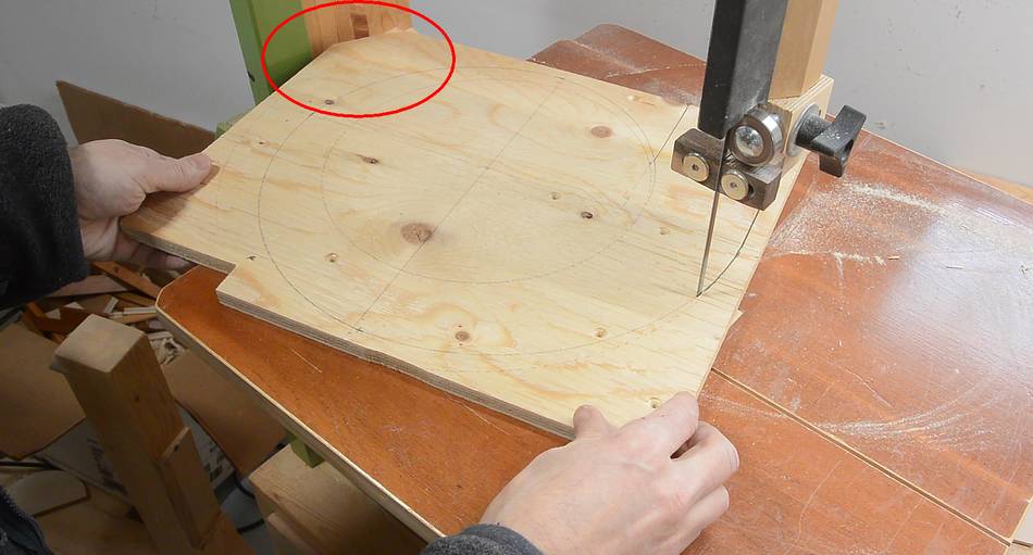 Cutting out the spiral shape on my 16" bandsaw.
I ended up hitting the post a few time (in this photo, circled in red, you can see the
corner I cut off to make room). I should have used my
20" bandsaw, but that bandsaw was set up as a
sawmill at the time.
Cutting out the spiral shape on my 16" bandsaw.
I ended up hitting the post a few time (in this photo, circled in red, you can see the
corner I cut off to make room). I should have used my
20" bandsaw, but that bandsaw was set up as a
sawmill at the time.
 I glued on some pieces of 2x4 to get the housing to the right height...
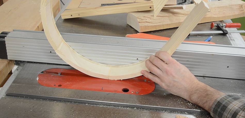
 ... then cut that out on my 18" bandsaw
This way of making the spiral housing was my best method yet. Faster than what I did for this one, this one, this one, or this one
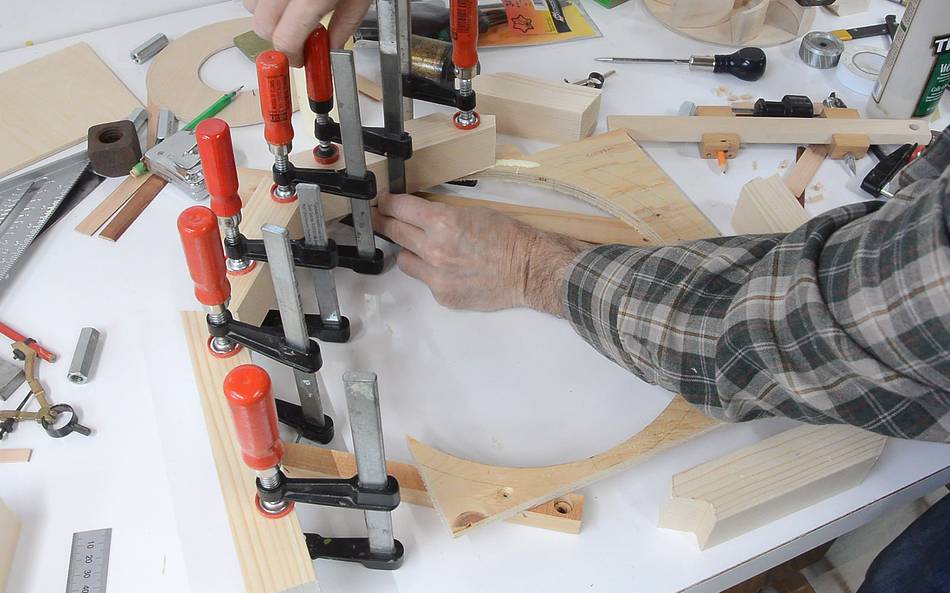
 The plywood held the pieces together already, but for extra robustness, I cut some slots
in the joints...
The plywood held the pieces together already, but for extra robustness, I cut some slots
in the joints...
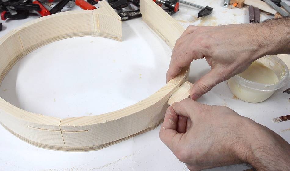
 ... and added splines to reinforce the joints. I cut off the excess on the bandsaw.
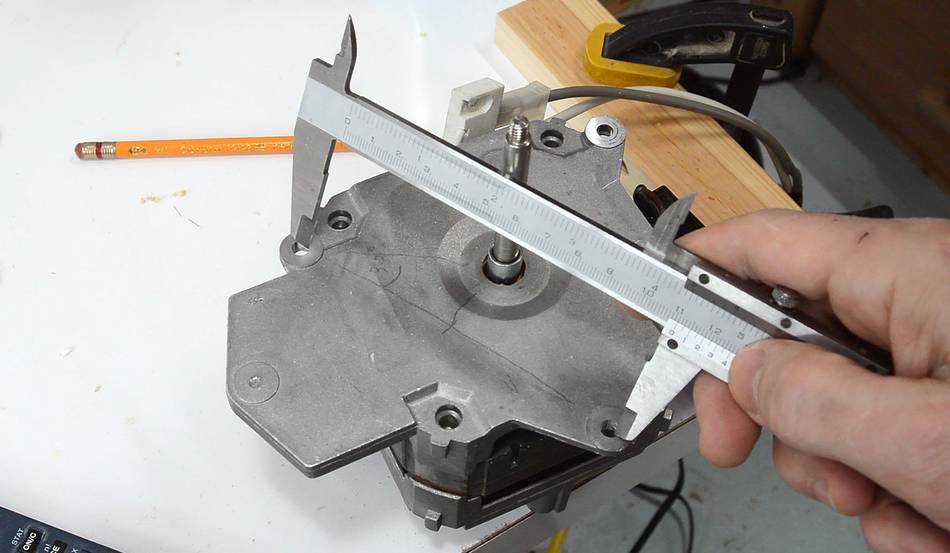
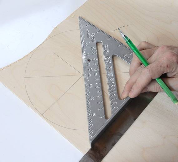
 I needed the layout for the mounting bolts on the motor. It turned out they were an
equilateral triangle. I worked out the radius of the bolt circle by taking the
length of the triangle, dividing that by two, then dividing by the cosine of 30 degrees
to get the radius. I then set a compass to that to mark a circle around
the center and then mark 120 degree angles from that and drilled out the holes.
I needed the layout for the mounting bolts on the motor. It turned out they were an
equilateral triangle. I worked out the radius of the bolt circle by taking the
length of the triangle, dividing that by two, then dividing by the cosine of 30 degrees
to get the radius. I then set a compass to that to mark a circle around
the center and then mark 120 degree angles from that and drilled out the holes.
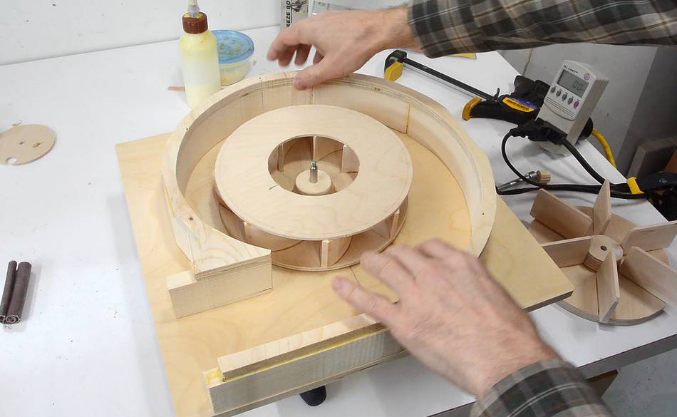 Putting it together, with the vanes forward-facing.
 I also made an impeller with straight vanes for comparison.
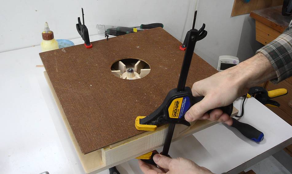 Clamping on a top cover...
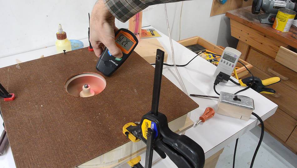
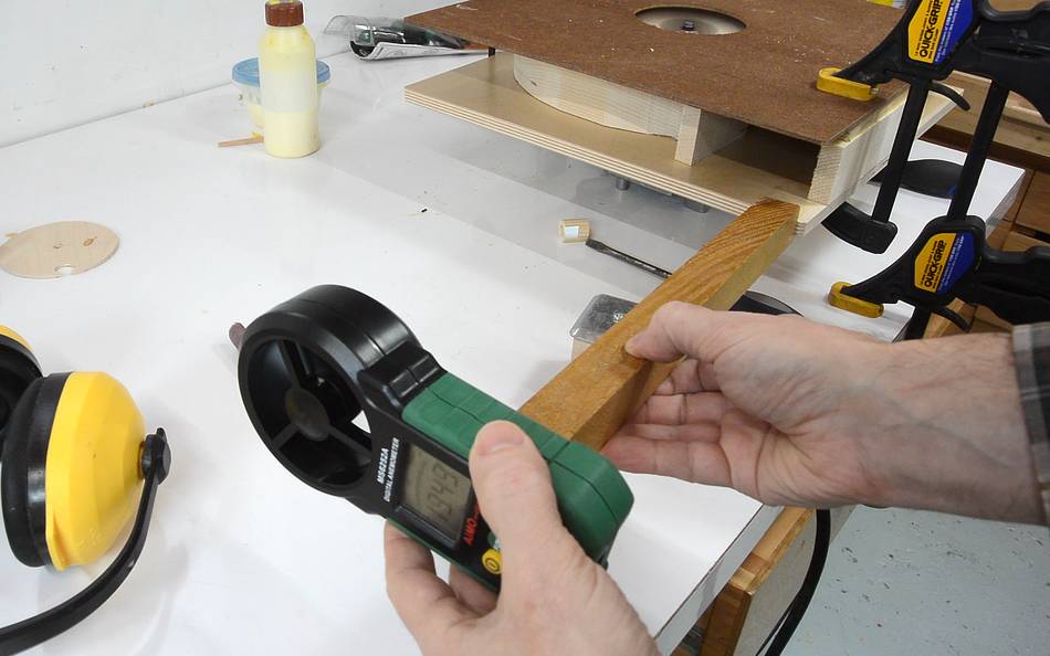 And measuring the maximum wind speed 35 cm from the blower.
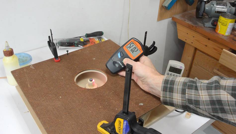 I also measured the RPM. With the forward curved impeller, the motor only spun
at 2015 RPM. The motor is supposed to run at 3150 RPM, so it was way overloaded.
I also measured the RPM. With the forward curved impeller, the motor only spun
at 2015 RPM. The motor is supposed to run at 3150 RPM, so it was way overloaded.
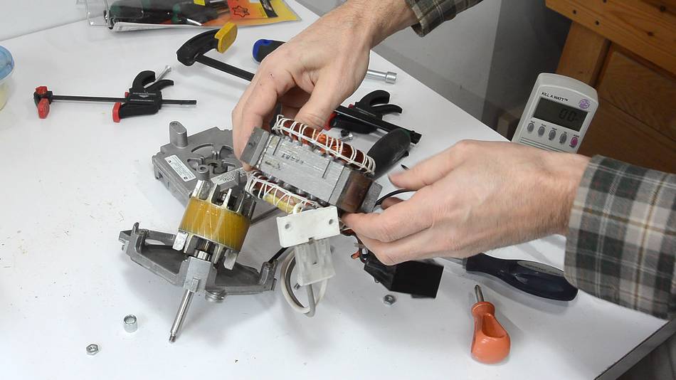 I then reversed the motor. Unfortunately the two windings are tied together
in the windings themselves, with only three wires brought out.
so I had to take the motor apart and flip the armature backward to reverse it.
I then reversed the motor. Unfortunately the two windings are tied together
in the windings themselves, with only three wires brought out.
so I had to take the motor apart and flip the armature backward to reverse it.
 I also flipped the spiral housing backward. So without making a new impeller,
I could test it with backward curved vanes.
I also flipped the spiral housing backward. So without making a new impeller,
I could test it with backward curved vanes.
 The load on the motor with the backward curved impeller was much less.
However, measuring various parameters, it's surprising that the forward curved
impeller produced the same wind speed coming out of it as the straight vaned impeller,
even though it was running at a much lower speed. But the forward curved impeller was
using much more power, whereas the backward curved impeller used the least amount
of power.
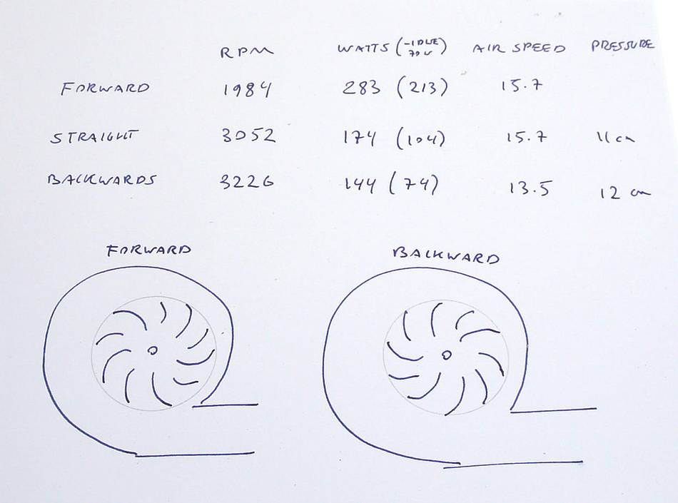 The forward facing impeller used dramatically more power (283 watts, or 213 watts more than
the motor uses when it's just idling). However, the motor was very overloaded with that
impeller, so it was much less efficient than it could be. But I was impressed that
even at two thirds the RPM, the impeller with forward facing vanes produced
the same wind speed. However, in terms of static pressure, the forward facing vanes
probably wouldn't help any. Certainly, the straight vanes didn't make as much
pressure as the backward curved ones. (I neglected to measure the pressure
from the backward curved vanes before reversing the motor).
The forward facing impeller used dramatically more power (283 watts, or 213 watts more than
the motor uses when it's just idling). However, the motor was very overloaded with that
impeller, so it was much less efficient than it could be. But I was impressed that
even at two thirds the RPM, the impeller with forward facing vanes produced
the same wind speed. However, in terms of static pressure, the forward facing vanes
probably wouldn't help any. Certainly, the straight vanes didn't make as much
pressure as the backward curved ones. (I neglected to measure the pressure
from the backward curved vanes before reversing the motor).
So forward facing vanes make sense if you want to maximize airflow for a limited size and RPM of blower. But I'm pretty sure the backward curved vanes are more efficient, though a larger impeller or higher RPM will be needed to get the same air flow.
I now understand why some blowers have forward facing vanes. Most squirrel cage blowers, such as furnace blowers, have forward facing fins. But blowers where pressure and efficiency are important (such as vacuum cleaners) tend to have backward curved vanes.
Next: Blower housing shape experiments
 Blower housing shape experiments
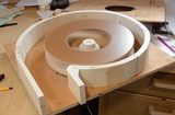 Blower design
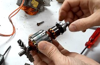 Oiling a noisy shopvac motor
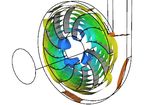
 Building my first dust collector blower
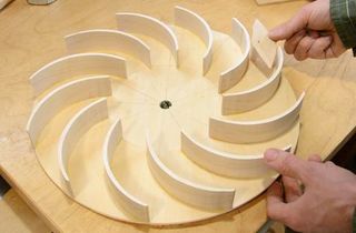 Second dust collector blower
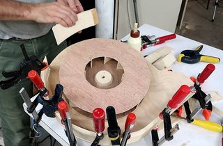 Building a blower for integrated dust collection
 2 x 45° elbow vs. 90° elbow air resistance test
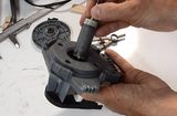 Using a syncronous diswasher motor
for a blower
Using a syncronous diswasher motor
for a blower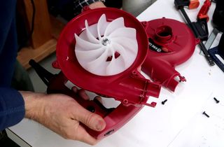 Miniature "leaf blower" experiments
 Dangerous 1 hp leaf blower