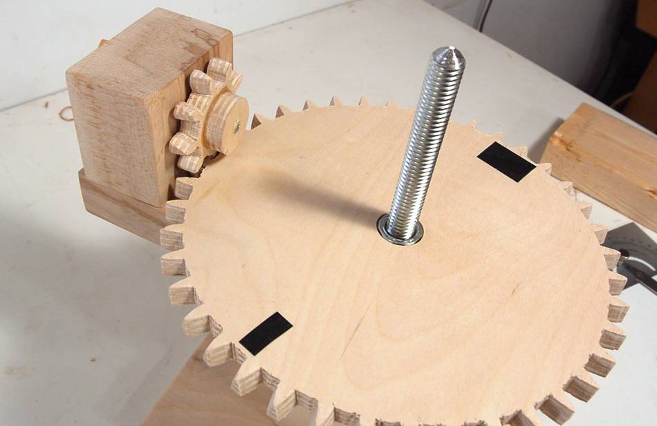
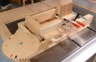
Once in a while, I need gears that work at a right angle, like for this
screw jack, or on my
box joint jig or
router lift.
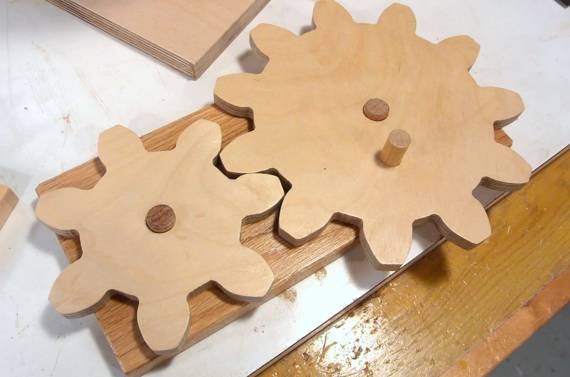
Plain flat gears will kind of work at 90 degrees, so long as both gears
have at least 12 teeth, but they run a bit rough. With my box joint jig gears, I started beveling the edges of the
teeth slightly, which helps. But when I made the gears for the tilting router
lift, I had the idea of beveling the sides of the teeth by the
amount of the contact angle, and that worked quite well.
A problem with beveling the sides of the teeth is that one side of the teeth can become
quite narrow. Ideally, the gear's teeth would have the shape of the template right in
the middle layer of the plywood. But the template has to be on one side or the other.
The solution is to widen the gear teeth by half the bevel amount to compensate.
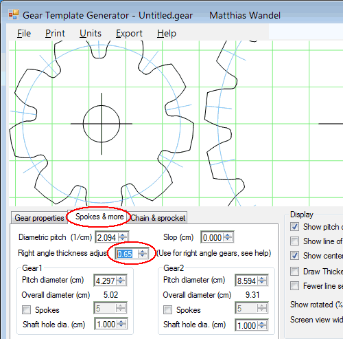
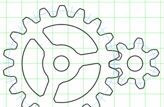
To make this easier, I've added this feature to my
gear generator program.
The right angle feature is new in version 3.1 (released Feb 2015). If you have version 3.0,
click on "Check for updates" under the "Help" menu to download version 3.1
Enter the thickness of the wood you are using under "Right angle thickness adjust"
in the "Spokes & more" tab. You may also want to adjust the addendum under
gear properties so that the tooth height is the same as the thickness of your plywood.
Addendum and dedendum are specified as multiples of the tooth spacing.
So if you use 3 cm tooth spacing with 1.8 cm thick plywood, the addendum and dedendum should
add to 1.8 / 3 = 0.6 . You should then set the addendum and dedendum to 0.3 to get
18 mm tall teeth on the gears.
One gear's addendum is the other gear's dedendum. So set
both values at the bottom of the "Gear properties" tab.
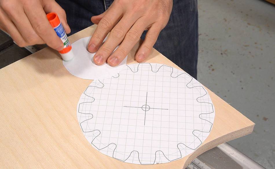
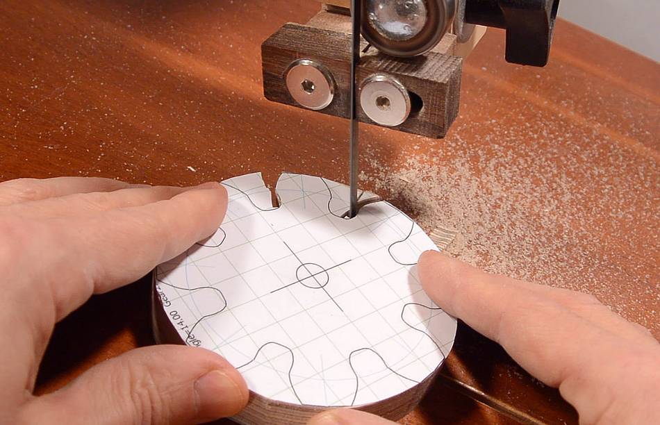
Once I have the templates printed, I glue them on with glue stick, applying the glue to the
back of the template, but only where the teeth are, plus a dab in the middle.
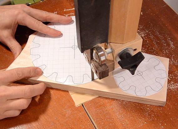
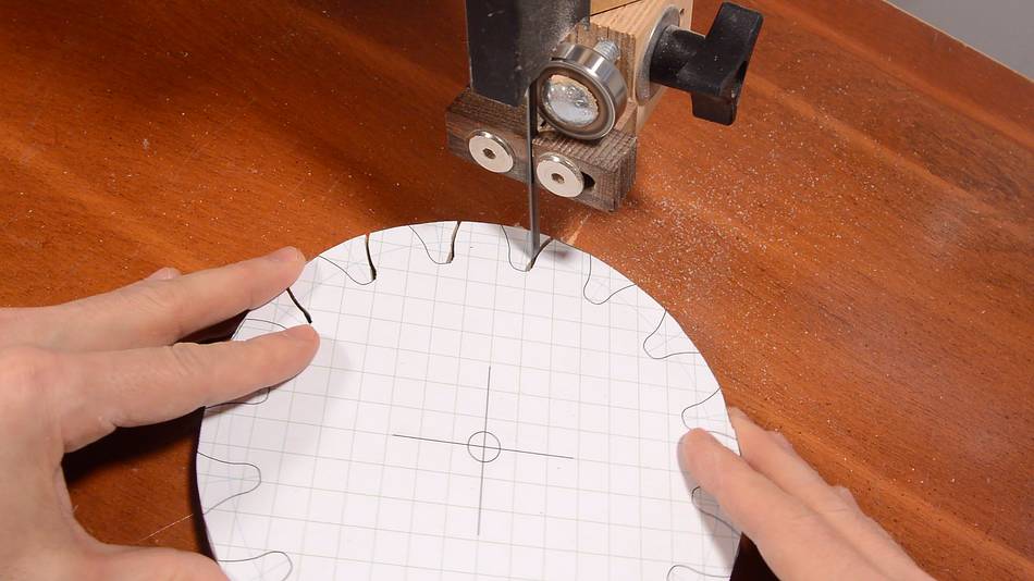
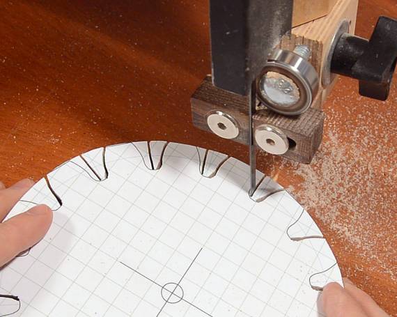
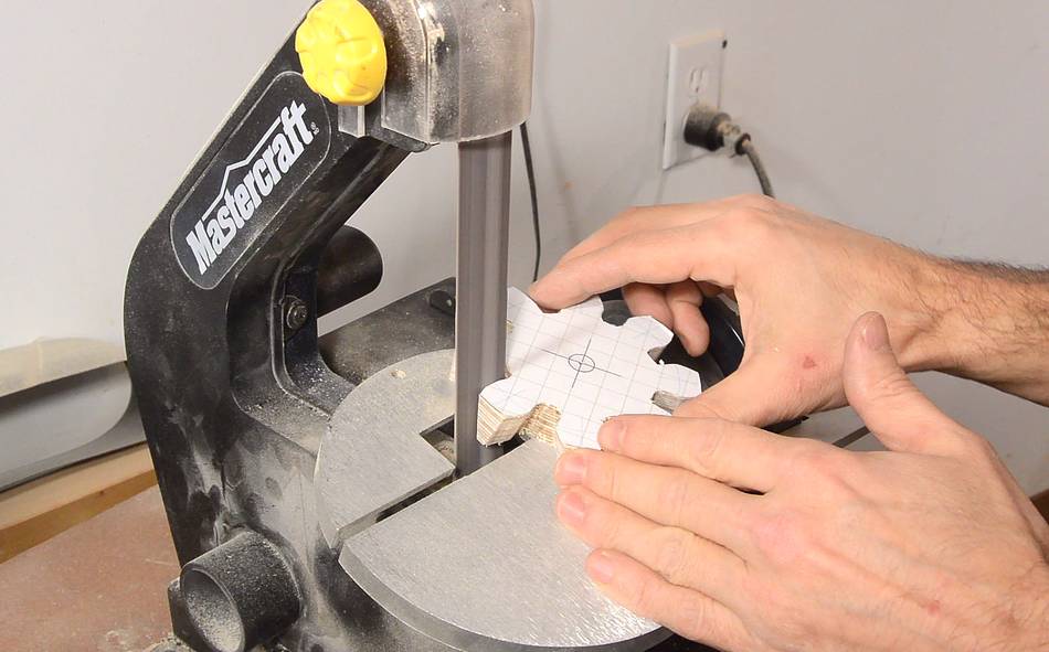
The tips of the teeth are not bevelled, so I cut out a circular outline to cut
the teeth to length before tilting the bandsaw table.
The teeth I'm making here have a 14-degree contact angle (also known as
pressure angle). The bevel is the same
as the contact angle, so I tilt the table 14 degrees.
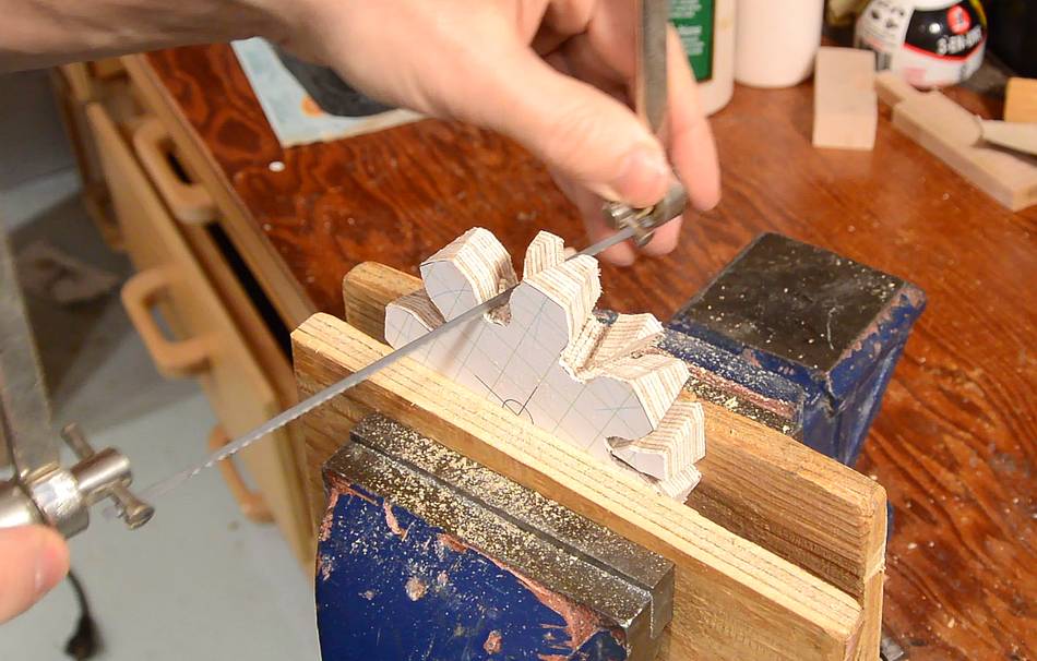
Then cutting the left side of every tooth. The teeth are fatter on the
template, so I need to cut such that the other side of the tooth will
end up narrower.
For the smaller gear, the curve of the tooth sides is sharp enough
that I need to do it with several cuts with my 1/4" bandsaw blade.
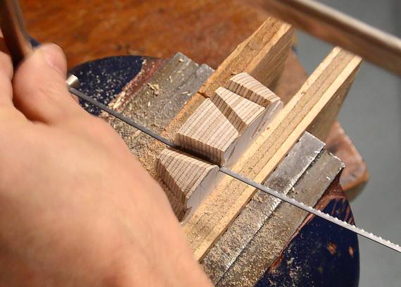
The other side of the teeth needs to be cut with the table tilted
in the opposite direction.
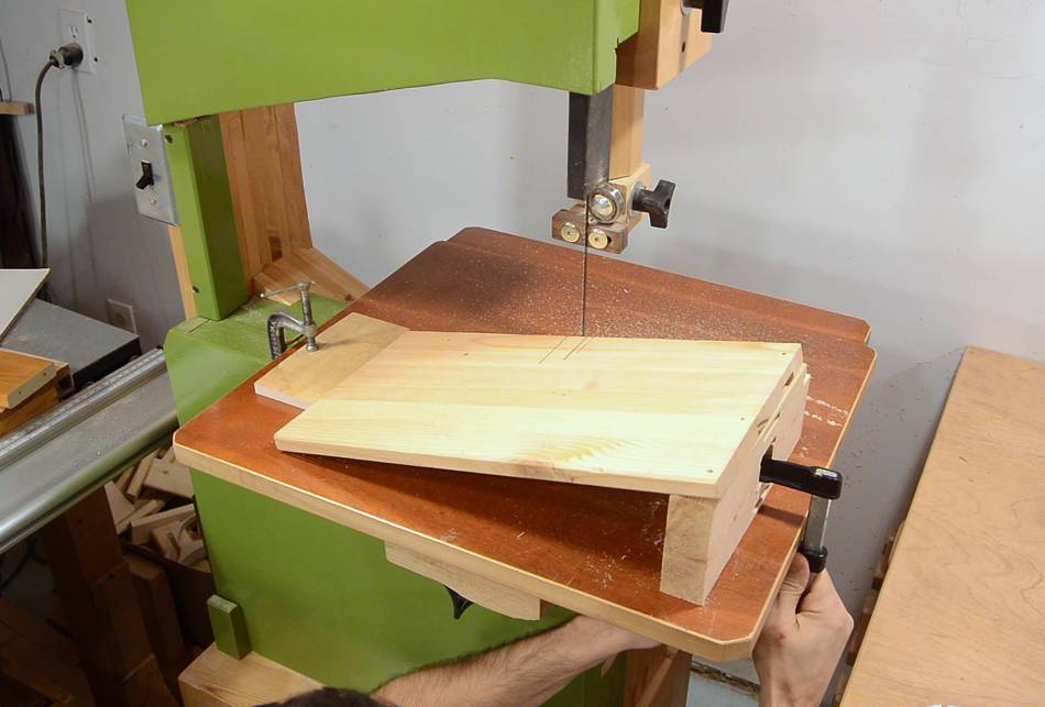
Most bandsaw tables only tilt to the right, so I'm jigging up a scrap of
wood on the table to get the other tilt.
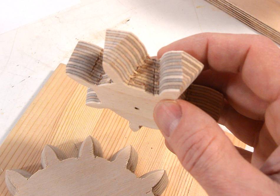
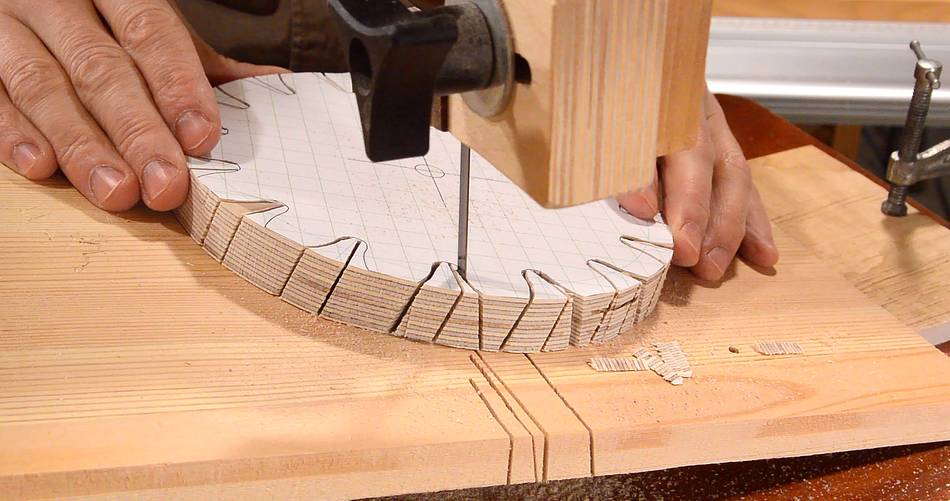
Cutting the other sides. You can see how the teeth taper narrower
towards the bottom.
I make several cuts to try to hog out some of the material, but it would be a lot
of work to remove all of it with the bandsaw.
So I remove the rest of the waste with a coping saw.
This was quick and easy, and, in retrospect, I really only needed to cut
a slot wide enough to get the coping saw blade in on one side of
each tooth. As I cut between the teeth, I change the angle of the
saw to meet up with the angled cut on the other side.
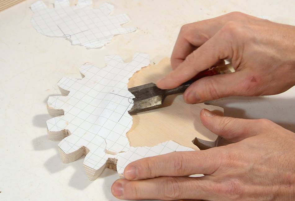
A bit more cleaning up with a chisel.
Next I clean the sides of the teeth with a strip sander, also with
the table at 14 degrees.
One of my main justifications for buying this strip sander was for sanding gear teeth,
though it comes in very handy for other things too. I still don't have a spindle
sander, so I use it for that type of work too.
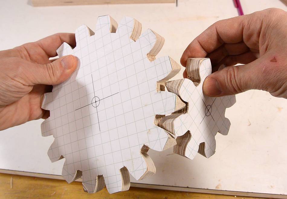
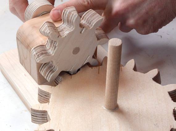
Checking how the teeth mesh.
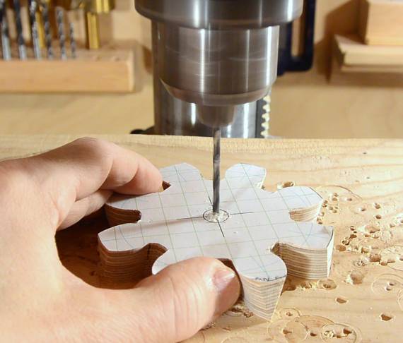
It's important to drill (or at least mark) the center hole location before removing
the paper templates.
Because I only used glue stick where the teeth are, and applied it to the paper,
not the wood, the templates come off easily with little residue.
I often get the suggestion to use spray adhesive, but I find that too
much hassle to deal with. The nozzle on the spray can gets plugged up,
even with cleaning. Overspray is also a problem. And the template
will be harder to peel off. Glue stick goes on slower, but is less work in
the end.
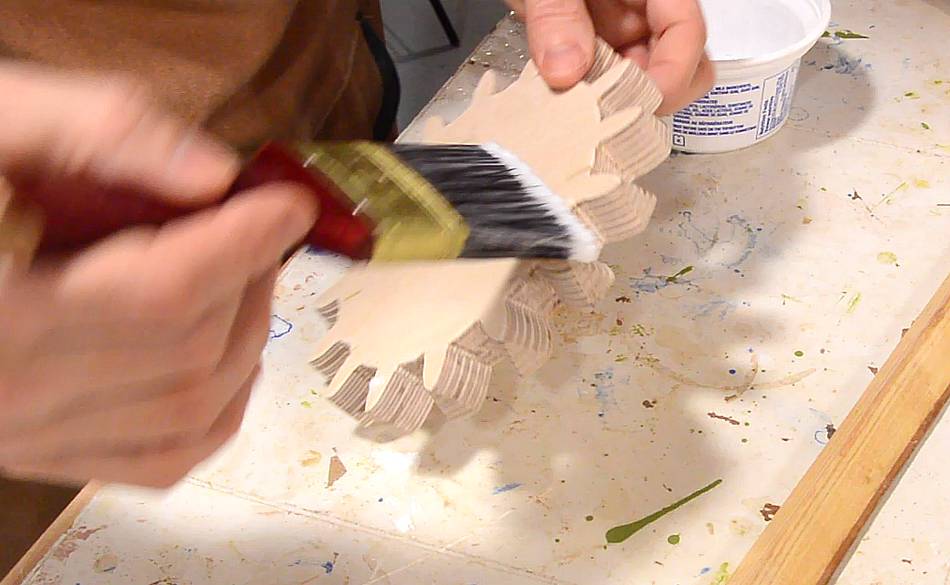
The rough edges of the plywood, even sanded, don't slide that easily. So
some treatment to the gear teeth improves how they run. I'm using Varathane
diamond floor varnish, which is quite slippery once two or more coats have
been applied. I imagine melting wax into the teeth would also work.
After that I drilled a 3/8" hole in the small one and a 1/2"
hole in the big one to mount them in a jig, being careful
that the holes are square to the plywood.
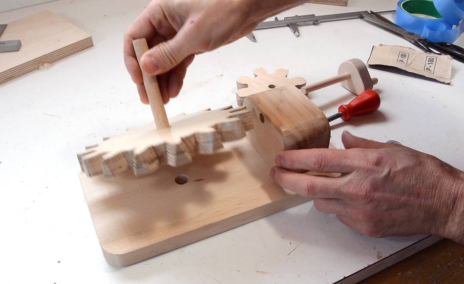
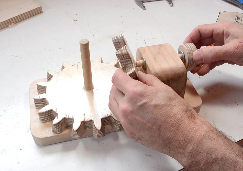
Here's the jig I built for mounting them.
The small gear fits tightly onto a dowel with a crank on the other side.
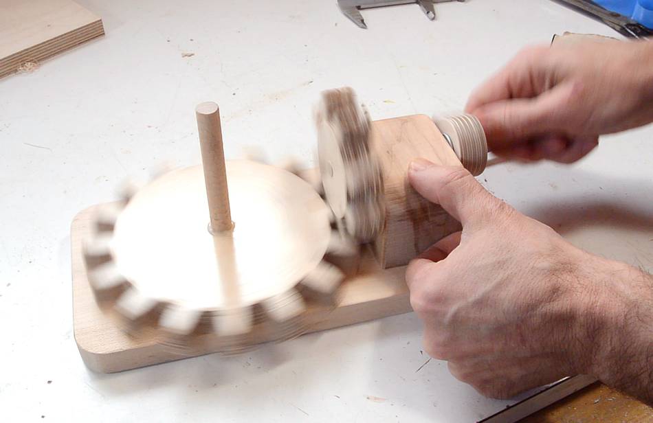
It's fun to crank the gear and watch them spin.
These work nice and smooth.
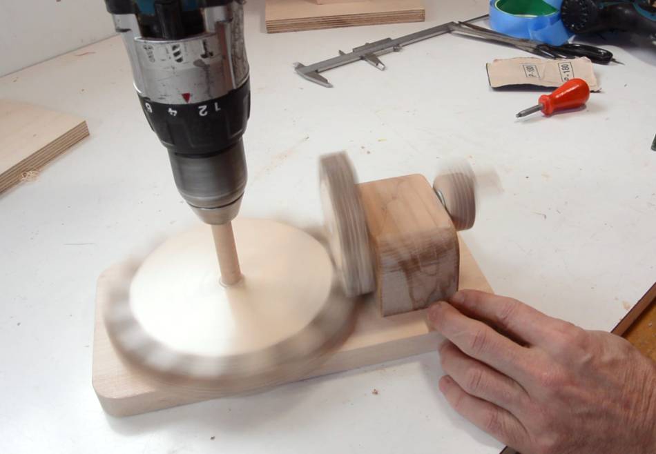
It's even more fun to spin the shaft of the big gear at high speed
with a drill!
 Once in a while, I need gears that work at a right angle, like for this
screw jack, or on my
box joint jig or
router lift.
Plain flat gears will kind of work at 90 degrees, so long as both gears
have at least 12 teeth, but they run a bit rough. With my box joint jig gears, I started beveling the edges of the
teeth slightly, which helps. But when I made the gears for the tilting router
lift, I had the idea of beveling the sides of the teeth by the
amount of the contact angle, and that worked quite well.
Once in a while, I need gears that work at a right angle, like for this
screw jack, or on my
box joint jig or
router lift.
Plain flat gears will kind of work at 90 degrees, so long as both gears
have at least 12 teeth, but they run a bit rough. With my box joint jig gears, I started beveling the edges of the
teeth slightly, which helps. But when I made the gears for the tilting router
lift, I had the idea of beveling the sides of the teeth by the
amount of the contact angle, and that worked quite well.


 Screw advance
 Tilting router lift
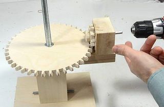 Screw jack for joint
 Pager rotating machine
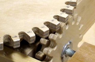 How to make
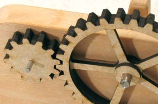 Cutting gears
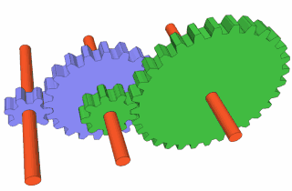 Working out compound
 Modeling gears to fit existing ones
 Bandsaw vs CNC
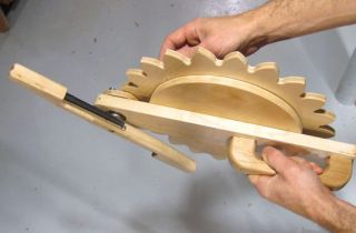 Pen shaking contraption
 Almonte clock tower clock