Wooden gear cutting jig
There's nothing that symbolizes machinery like gears. Seeing that I
like to make machines out of wood, it follows then that I should want some
of these machines to have gears on them. Wooden gears, of course.
I have cut numerous wooden gears on my table saw for various machines,
such as my
Marble machine 2.
One of the biggest problems with this is precisely measuring the angle
between the teeth, and rotating the gear by exactly that much between cuts
on the table saw. With the gear jigged up on a shaft to hold it
securely, it isn't possible to attach a protractor to measure accurately.
And even when using a protractor, there is always the problem that
the protractor has to be moved (seeing that it doesn't span 360 degrees),
and the possibility of getting some slightly odd teeth intervals as a result.
 To help rotate the
gear by a precise amount for the purpose of cutting teeth, I decided to build
some kind of mechanism for rotating the jigged-up gear. The idea is to
have something to roughly take the role of a machinist's dividing plate, but
much smaller, lighter, and less precise.
To help rotate the
gear by a precise amount for the purpose of cutting teeth, I decided to build
some kind of mechanism for rotating the jigged-up gear. The idea is to
have something to roughly take the role of a machinist's dividing plate, but
much smaller, lighter, and less precise.
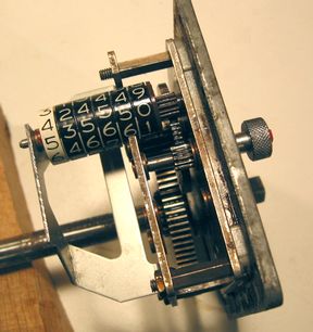
Rummaging through my junk, I was fortunate enough to find a remote servo
(for controlling valves and such), of roughly 1940's technology.
The box consisted of a small split phase motor,
5 stages of reduction gears to a big gear on a half inch shaft, a rheostat,
and some sort of mechanical balance contraption to function a bit like a
bridge circuit to compare the rheostat in the box to some master rheostat
somewhere else. When unbalanced, the balance would connect either phase
of the split phase motor to AC power, causing it to rotate in either direction.
YouTuber AvE made a
video about one of
these servos
I removed the motor and the gears closest to it, leaving me with two
gears of reduction. I mounted the last remaining shaft and gear backwards
so that the long shaft protruded out through a hole I drilled in the aluminium
plate, and attached a knurled knob to it for fine adjustment.
I then needed some means of measuring rotations of the knob.
I originally thought of using a counter from a tape recorder, but I found
an old set of mechanical car odometer wheels in my parts collection. The gear attached
to the last wheel was exactly the right pitch to match with those in my
gearbox. Unfortunately, the first (0.1 km increments) wheel of the odometer
was designed to jam up on running backwards. The rest of the wheels
didn't have this property. So I moved the 0.1 km increment
wheel to the other end, and made the gear drive the 1 km increment wheel
directly. With the various gears, I got a 1:39.12 gear ratio.
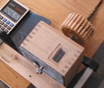
The gear cutting jig in action on the table saw.
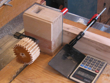
I then made a sturdy wooden box to attach to the aluminum frame of the gearbox,
and keep my gears free from dust. The way I use the jig on my table saw
sled causes the sawdust to get thrown directly towards the gearbox, so keeping
the dust out is important. I even made a little window for
the counter so no dust can get in that way either.
The whole mechanism runs really smoothly. A light twist to the output
shaft will set the odometer counter spinning. This turned out to be
a bit of a problem when cutting gears, because I always apply a slight amount
of torque to the output shaft while cutting to avoid random errors from
gear backlash. But with the mechanism turning so easily,
I need to add a brake to the input knob so that it doesn't start spinning
from this slight torque.
A gear ratio of 1:36 would have made the counter increments 1 degree.
Unfortunately, that was not the gear ratio that I had. I was already lucky
enough to have a gearbox as suitable for
the job as it was. Besides, most gears I make don't have a number of teeth
that would divide nicely into 360 anyway.
As it is, I have 391.2 counter increments per revolution. When
I cut the gears, I calculate how many increments I need to advance per tooth,
and then use the constant calculation feature of a calculator to generate
the numbers one at a time, and dial them on my counter. 391.2 increments
is unfortunately too few to just round to the nearest, so I have
to visually interpolate fractional increments to get decently accurate gear tooth spacing.
For most gears, I have to make two cuts per tooth, so I have to dial in two
angles per tooth.
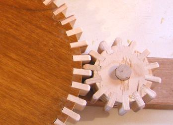
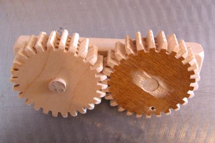
The two gears above were the first ones I cut with my jig. To round the tops
of the teeth, I used a square file, held at a 45 degree angle, and filed between
two adjoining teeth. This kind of approximates the ideal involute spur gear
tooth shape. These two gears mesh amazingly smoothly for being cut out of plywood.
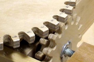
Gears with inset teeth
Naturally, cutting the gears straight out of plywood
is not ideal because the wood grain is not aligned with the teeth.
Better gears can be made by inserting individual teeth
into a plywood wheel. Unfortunately, this means the teeth have to be
fairly narrow to leave enough plywood to hold them. At left are two gears made this way.
The small gear only has 14 teeth, and it
runs fairly noisily. This can be desirable for drawing attention,
as in "look, it has wooden gears!"
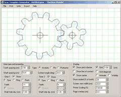
Since building the gear cutting jig, I have come up with a simpler solution for
getting all the gear angles. It's much easier to just make a protractor
template out of paper and stick it to the piece of wood.
This should help align the angles,
and with care should be more than accurate enough. You can make very
accurate protractor templates with an inkjet printer using my free
online gear template generator or
you could buy a copy of my fancy gear template generator.
 How to make gears
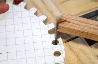 Cutting gears with a jigsaw
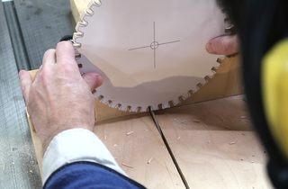 Cutting gears with a table saw (freehand)
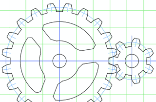 Free interactive gear template generator
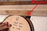

 Gear design and gear