I wanted to try making a wooden four-jaw chuck for my lathe.
My plan all along was that the four jaw chuck would be permanently attached to
a drive shaft, which I'd swap into the lathe when I needed to use the chuck.
But I wanted this drive shaft to be a bit thicker to have more support for bowl turning, so I used some 16 mm polished steel rod that I had lying around.
This meant I needed bigger bearing blocks. I also wanted to switch to hanger bolts to mount them. With those changes, I needed the mounting holes to be further apart. The easiest solution was to just make another headstock for the lathe.
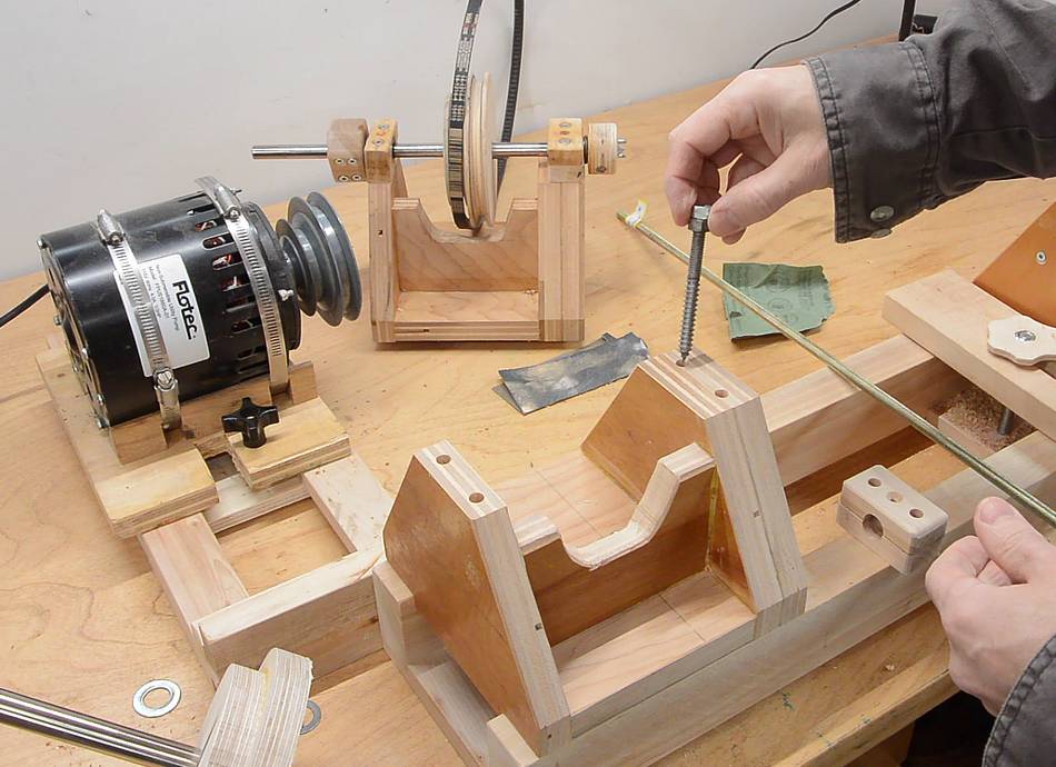
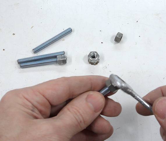
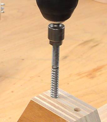 The "hanger bolts" have a wood screw thread on one end and
a machine thread on the other. I jammed two nuts against each other on the end of
the bolt and used a nut driver in a drill to drive them in.
The "hanger bolts" have a wood screw thread on one end and
a machine thread on the other. I jammed two nuts against each other on the end of
the bolt and used a nut driver in a drill to drive them in.
Another alternative would have been to just use threaded rod, and screw that into
slightly undersized holes in the wood, along with some glue.
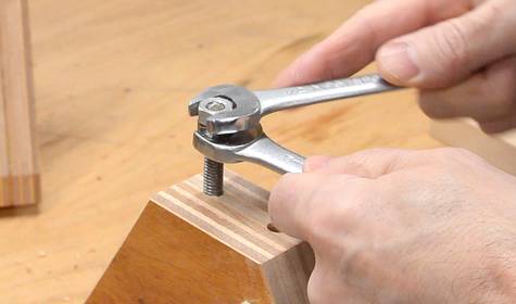
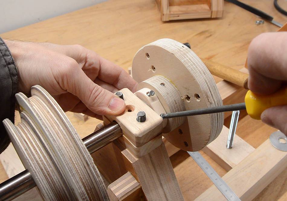
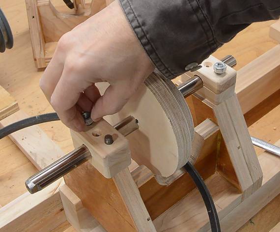 The machine screw thread on the hanger bolts makes it easier to open up
the bearing blocks to swap the shaft. It's just a matter of removing the nuts.
The machine screw thread on the hanger bolts makes it easier to open up
the bearing blocks to swap the shaft. It's just a matter of removing the nuts.
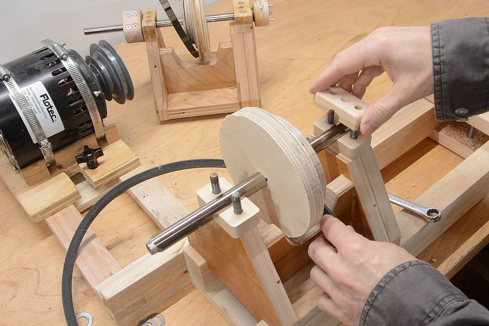
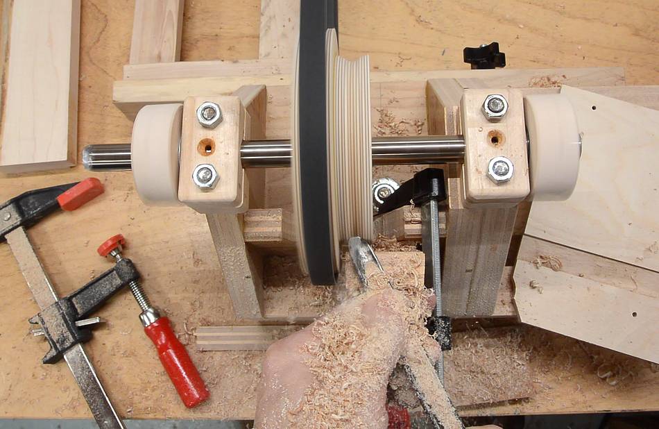
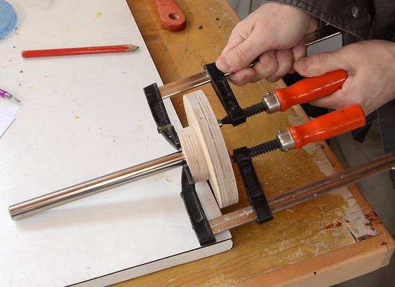
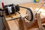
 I used the same method for shaping the pulley as last time, with the V-belt
first riding on the unshaped lower step pulley. I had to make some blocks
to clamp on either end of the shaft to keep it from sliding side-to-side.
I used the same method for shaping the pulley as last time, with the V-belt
first riding on the unshaped lower step pulley. I had to make some blocks
to clamp on either end of the shaft to keep it from sliding side-to-side.
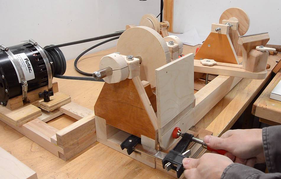 A scrap of plywood clamped to the front of the lathe serves as a
temporary tool rest.
A scrap of plywood clamped to the front of the lathe serves as a
temporary tool rest.
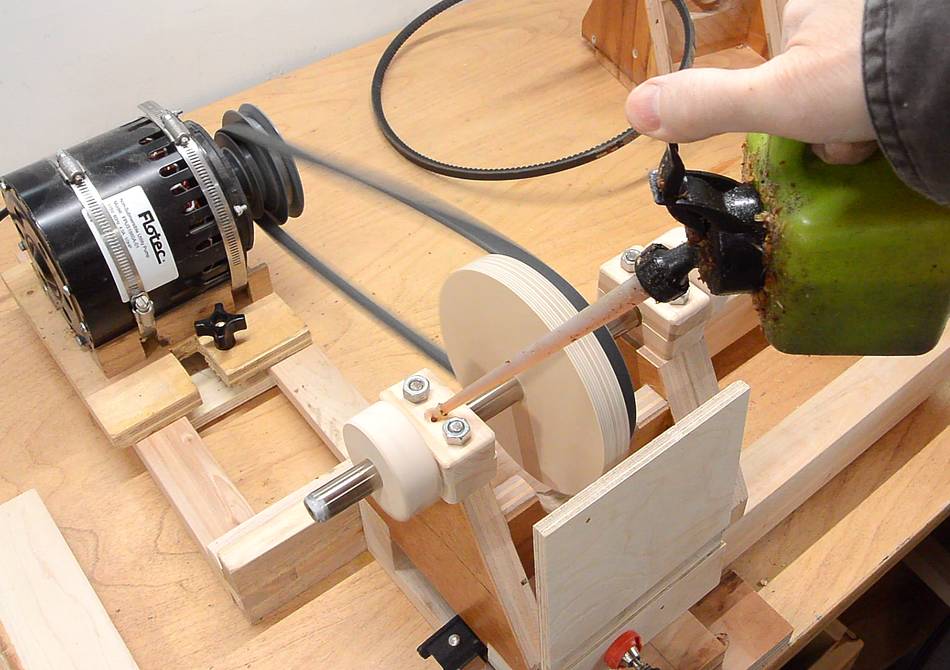 It's also important to oil the bearings before running it for an extended period.
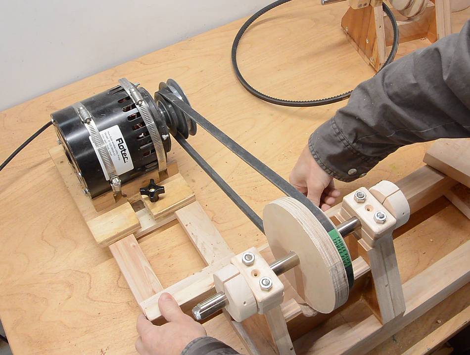
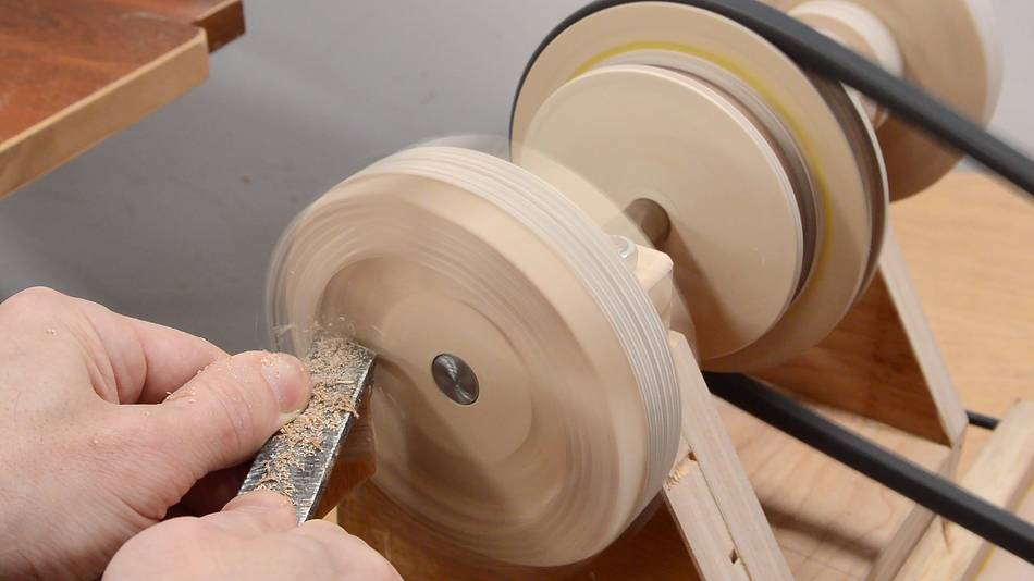
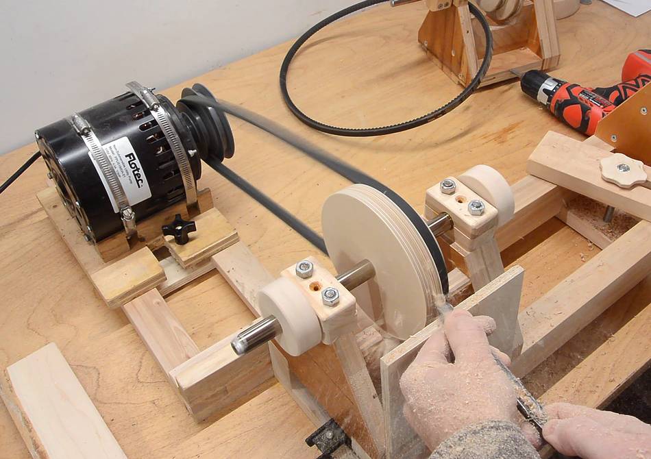 I turned the larger pulley round and then made a shallow groove in it.
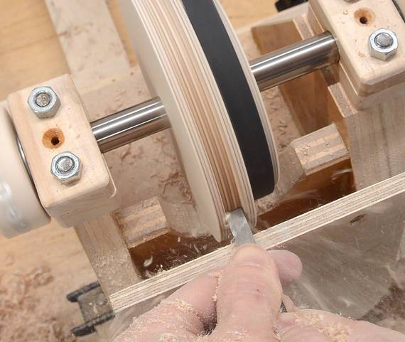 Once I had a shallow groove, I put the belt in it and started turning the
smaller pulley. Once that was turned, I put the belt in the smaller pulley's
groove and finished turning the larger pulley.
Once I had a shallow groove, I put the belt in it and started turning the
smaller pulley. Once that was turned, I put the belt in the smaller pulley's
groove and finished turning the larger pulley.
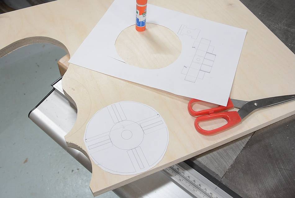 I used my BigPrint program to
print a 1:1 template of the main part of the chuck, and cut it out of
Baltic birch plywood.
I used my BigPrint program to
print a 1:1 template of the main part of the chuck, and cut it out of
Baltic birch plywood.
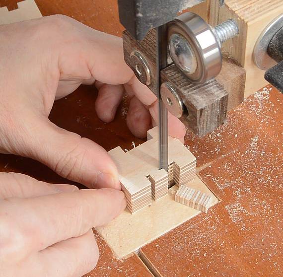
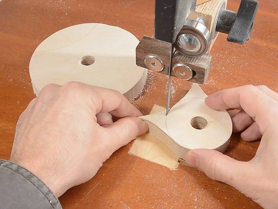
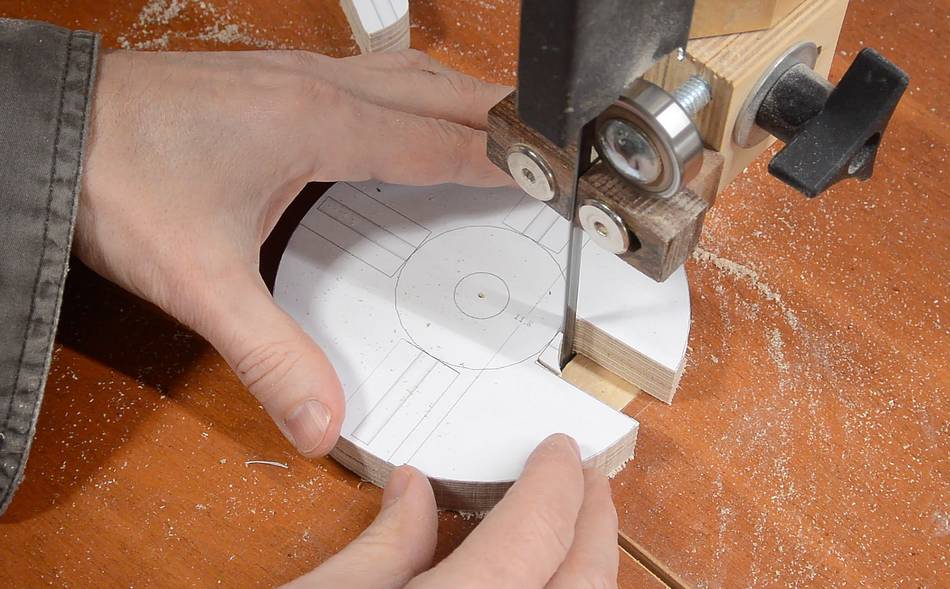 Carefully cutting out the main part on the bandsaw.
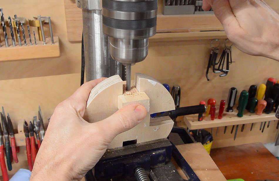
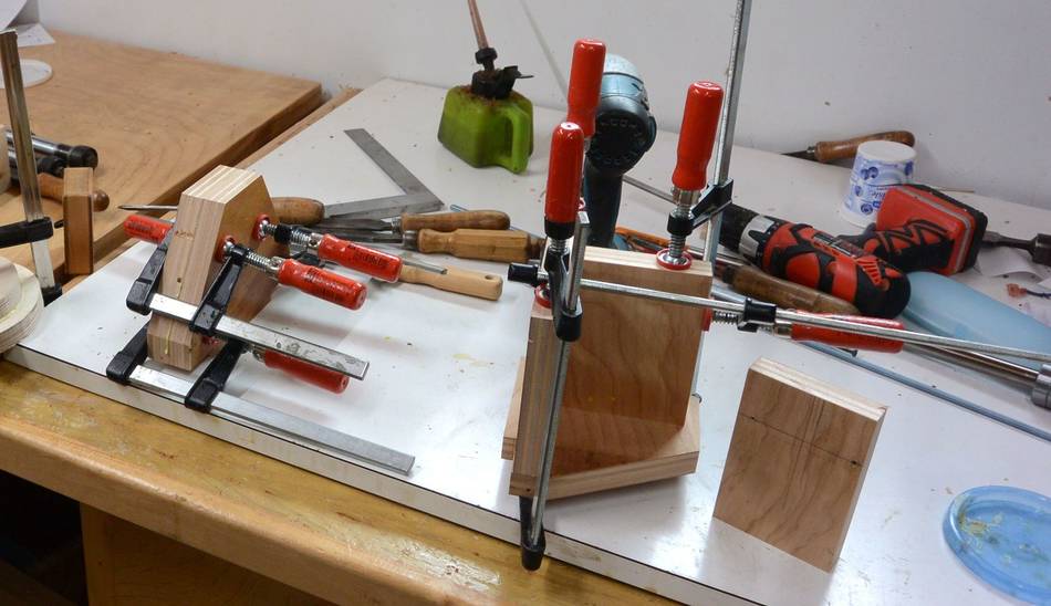
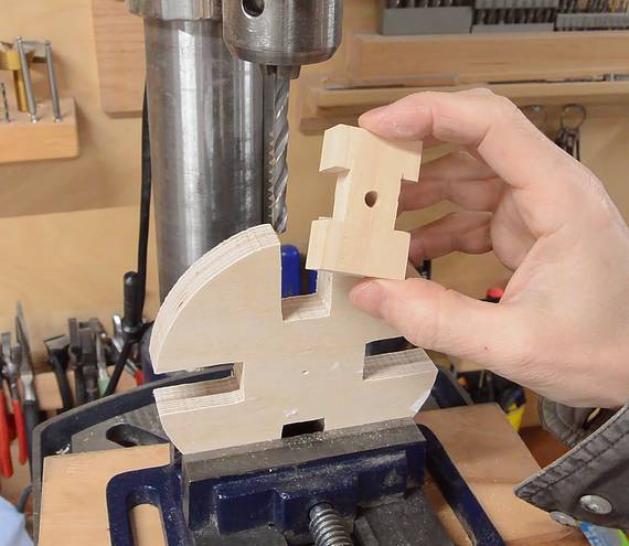 A piece of threaded rod will go into each of the four slots. This needs to
go in fairly precisely. So I made a drilling guide that fits in the slot
to help guide the drill. I drilled 15/64" holes for the 1/4" threaded rod
(the holes are slightly smaller than the threaded rod).
A piece of threaded rod will go into each of the four slots. This needs to
go in fairly precisely. So I made a drilling guide that fits in the slot
to help guide the drill. I drilled 15/64" holes for the 1/4" threaded rod
(the holes are slightly smaller than the threaded rod).
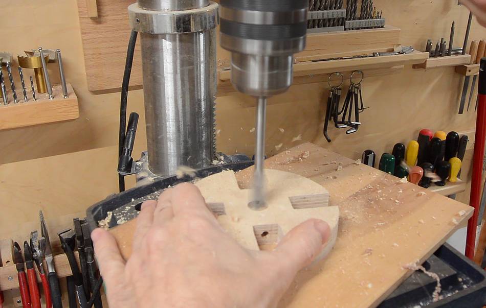 Then drilling out the main hole with a spade bit. I'm not very fond of
using spade bits, but I ground this one down a bit to make for a tight
fit with my 16 mm steel shaft.
Then drilling out the main hole with a spade bit. I'm not very fond of
using spade bits, but I ground this one down a bit to make for a tight
fit with my 16 mm steel shaft.
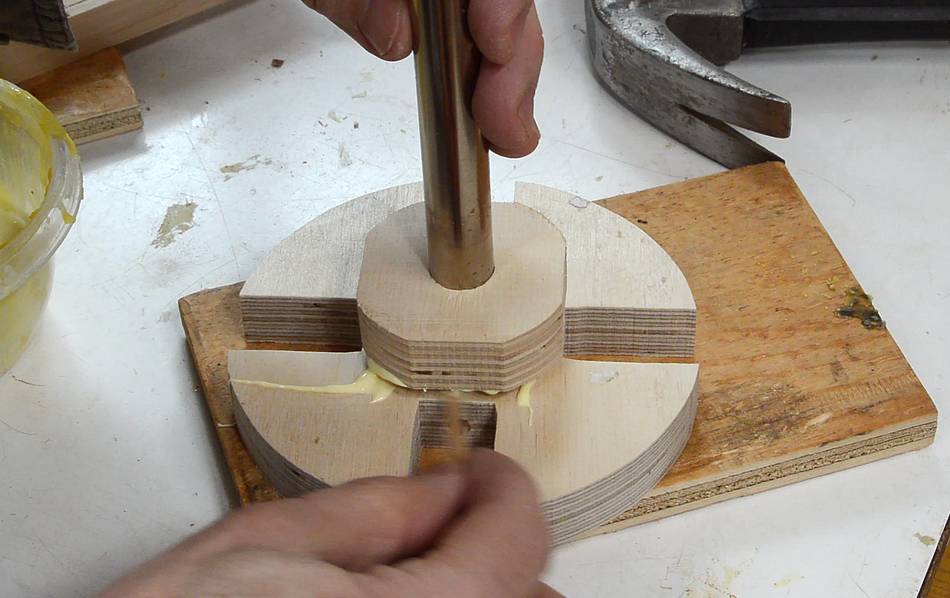
 I used a spare piece of 16 mm shaft to line up the hole in the main part
with the extra layer while gluing it together.
I used a spare piece of 16 mm shaft to line up the hole in the main part
with the extra layer while gluing it together.
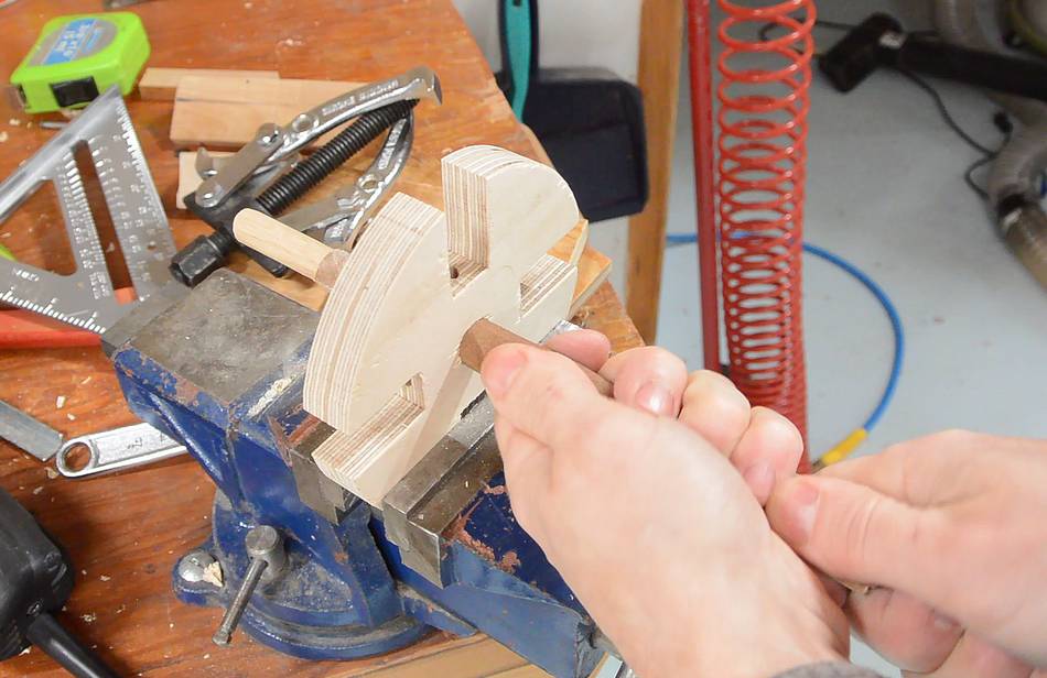
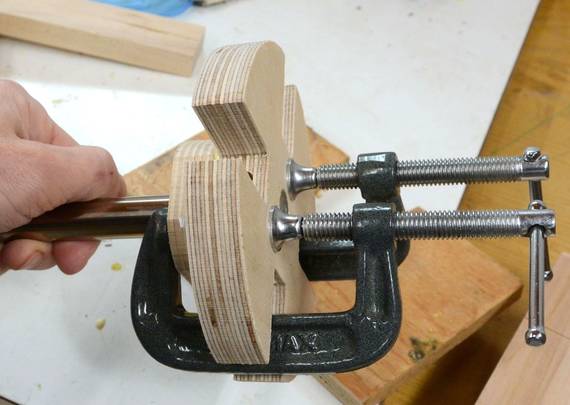
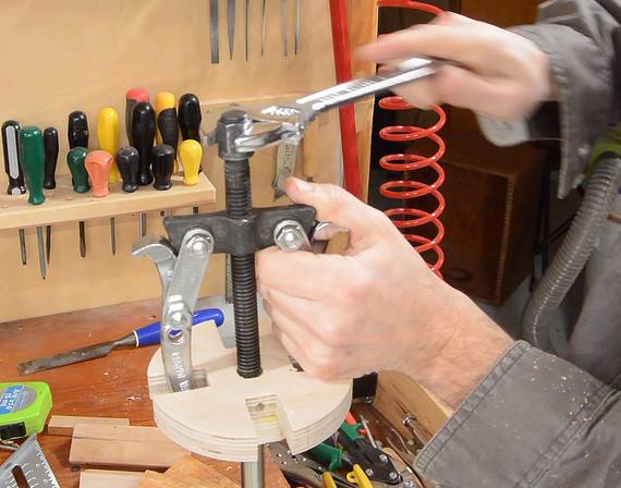 The hole was a little too tight, so I had to use a gear
puller to remove it from the spare shaft. I wrapped some sandpaper around
a dowel to sand the hole a bit larger.
The hole was a little too tight, so I had to use a gear
puller to remove it from the spare shaft. I wrapped some sandpaper around
a dowel to sand the hole a bit larger.
 I drilled a hole though the steel shaft and my chuck so I could attach
it with a pin through both.
I drilled a hole though the steel shaft and my chuck so I could attach
it with a pin through both.
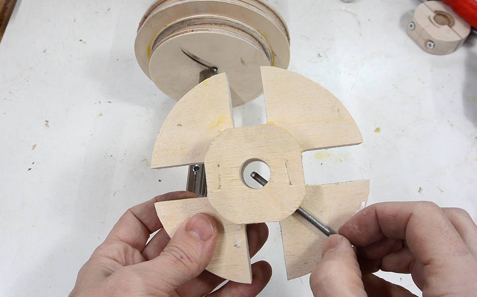 I used a nail as the pin. Usually when I do this, the holes end up
not quite through the center, so I orient it so the misalignment is in
the same direction on both parts. But this time, I got the hole in the
shaft unusually centered. I expanded the hole in the wooden part
a bit so the pin could go through the center of it.
I used a nail as the pin. Usually when I do this, the holes end up
not quite through the center, so I orient it so the misalignment is in
the same direction on both parts. But this time, I got the hole in the
shaft unusually centered. I expanded the hole in the wooden part
a bit so the pin could go through the center of it.
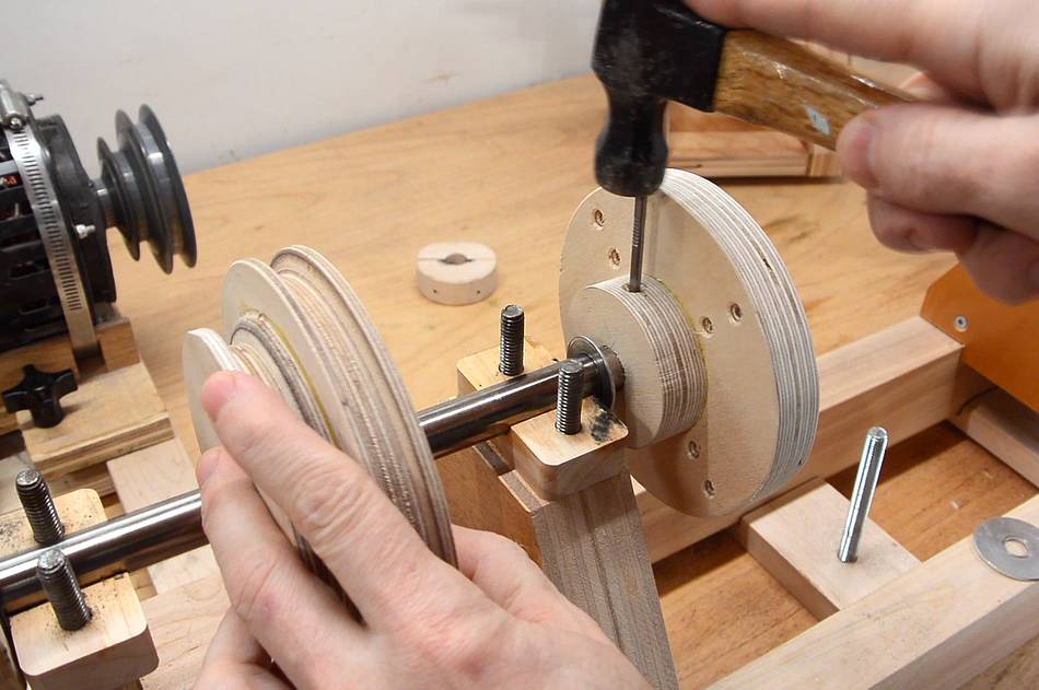
 I ground a point on the end of the pin (which is just a cut-off nail),
then used a piece of wood and a hammer to drive the pin through both parts.
The point on the end helps to align the parts as it goes through.
I ground a point on the end of the pin (which is just a cut-off nail),
then used a piece of wood and a hammer to drive the pin through both parts.
The point on the end helps to align the parts as it goes through.
 Manually spinning it on the headstock to check for wobble. I got lucky, and
the side-to-side wobble even at the edge of my chuck was less than 1 mm.
Manually spinning it on the headstock to check for wobble. I got lucky, and
the side-to-side wobble even at the edge of my chuck was less than 1 mm.
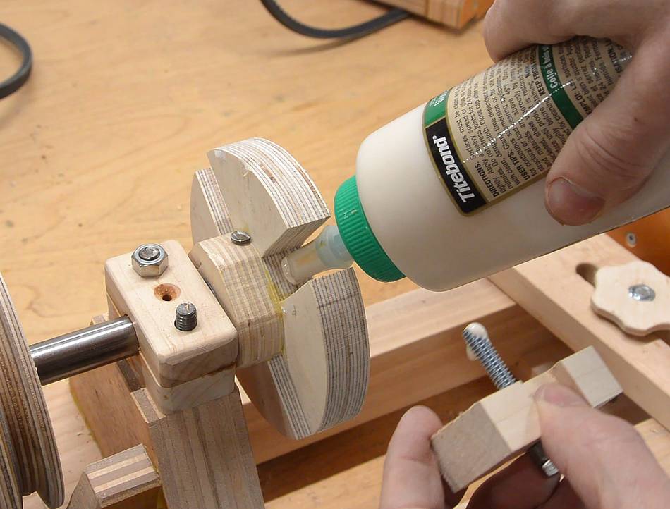 I sized the holes so that the 1/4" threaded rod fit tightly in the holes
in the chuck, but to make extra sure they wouldn't pull out, I also put wood
glue in the holes and on the threads. Wood glue doesn't stick very well
to the metal, but it will stick to the wood and form threads that mesh with
those of the threaded rod.
I sized the holes so that the 1/4" threaded rod fit tightly in the holes
in the chuck, but to make extra sure they wouldn't pull out, I also put wood
glue in the holes and on the threads. Wood glue doesn't stick very well
to the metal, but it will stick to the wood and form threads that mesh with
those of the threaded rod.
 I put two nuts jammed against each other on the end of the threaded rod,
then used a nut driver in a drill to drive them in.
I put two nuts jammed against each other on the end of the threaded rod,
then used a nut driver in a drill to drive them in.
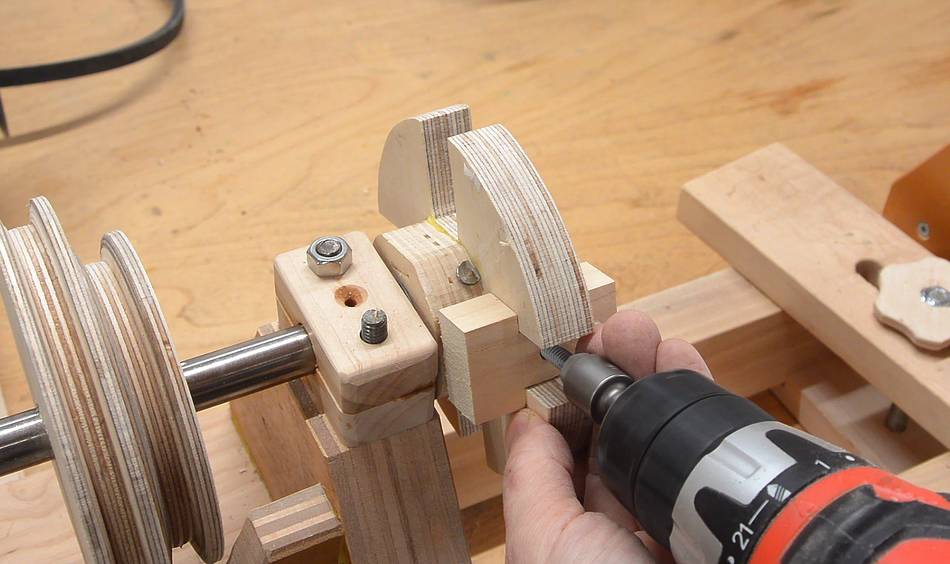
I expanded the hole in the guide block to 1/4" and then used it to help guide the threaded rod in straight.
 I then made four blocks, similar to my guide block, out of Baltic birch
plywood (though I guess any dense, closed grain hardwood would have worked
just as well).
I then made four blocks, similar to my guide block, out of Baltic birch
plywood (though I guess any dense, closed grain hardwood would have worked
just as well).
I was very careful to get these very precise.
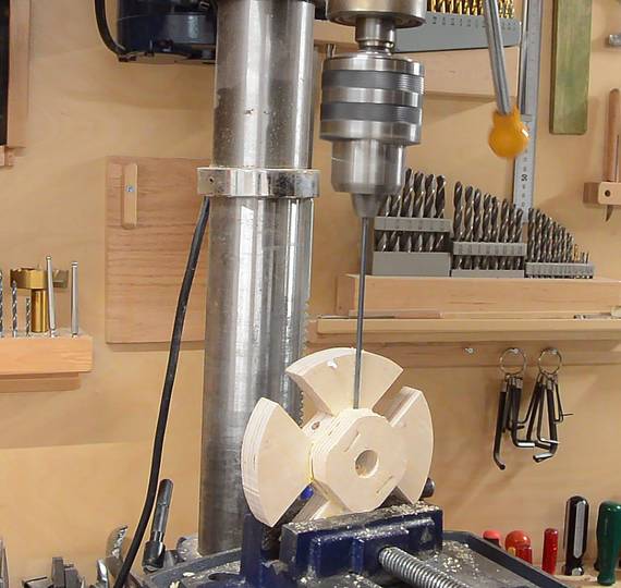
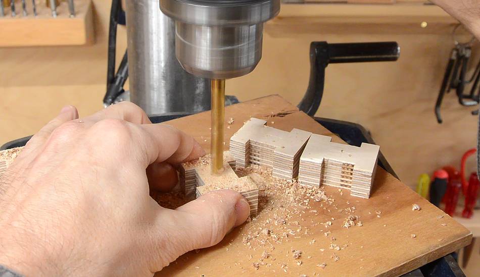 Here drilling the holes, 17/64" in size to provide a tiny bit of clearance
with the 1/4" threaded rod. I marked the locations by scoring with the
jaws of my callipers, then punched a divot using an awl. The point of the
Forstner bit naturally follows the divot.
Here drilling the holes, 17/64" in size to provide a tiny bit of clearance
with the 1/4" threaded rod. I marked the locations by scoring with the
jaws of my callipers, then punched a divot using an awl. The point of the
Forstner bit naturally follows the divot.
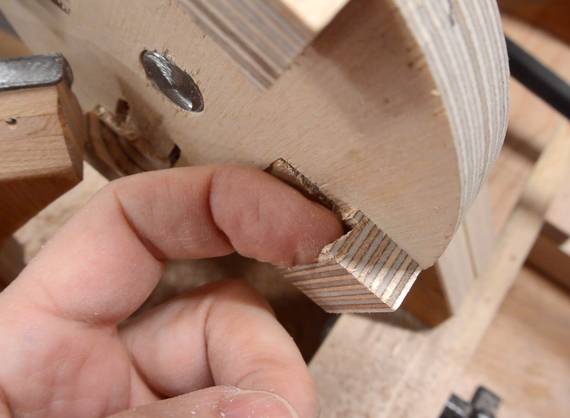
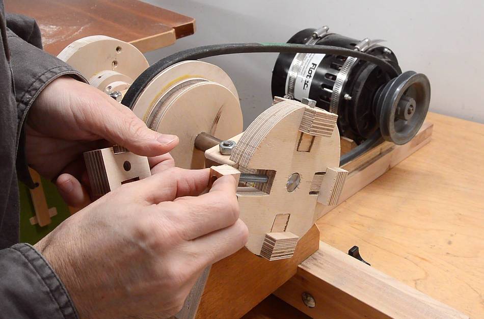 The jaws need to have a sort of "dovetail" cut into the inside of them.
I figured the best way to cut that was on the lathe. I made some spacers
to allow me to tighten the jaws while they are still moved all the way out.
The jaws need to have a sort of "dovetail" cut into the inside of them.
I figured the best way to cut that was on the lathe. I made some spacers
to allow me to tighten the jaws while they are still moved all the way out.
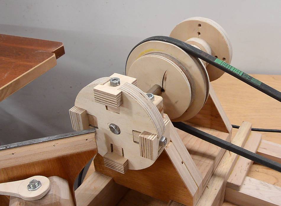 Ready for turning the dovetails into the jaws.
 I used a skew chisel to cut these from the inside. This was not a
particularly safe operation.
I used a skew chisel to cut these from the inside. This was not a
particularly safe operation.
In fact, this whole chuck is kind of scary unsafe. If the threaded rods come loose, or the nuts become undone, part of the chuck would just go flying. Staying out of the plane of rotation of the chuck, and/or using a face shield would be advisable.
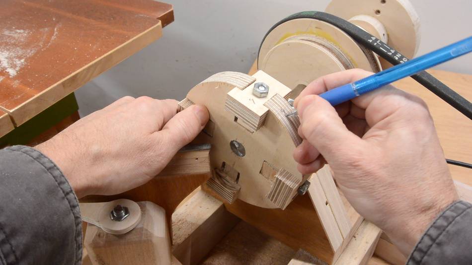 Having turned these jaws on the chuck itself, it automatically compensates
for any wobble that the main body of the chuck may have,
provided I always put them back in the same slots.
So I numbered the jaws and slots to make that easier.
Having turned these jaws on the chuck itself, it automatically compensates
for any wobble that the main body of the chuck may have,
provided I always put them back in the same slots.
So I numbered the jaws and slots to make that easier.
 The idea of these jaws is that they clamp onto a dovetail that is turned
onto the bottom of a workpiece. But to turn the dovetail on the bottom
in the first place, a raw blank first needs to be mounted on a faceplate
with screws.
The idea of these jaws is that they clamp onto a dovetail that is turned
onto the bottom of a workpiece. But to turn the dovetail on the bottom
in the first place, a raw blank first needs to be mounted on a faceplate
with screws.
So before I could try out this chuck, I needed to make a faceplate.
 Making the faceplate was very similar to making the chuck, but simpler.
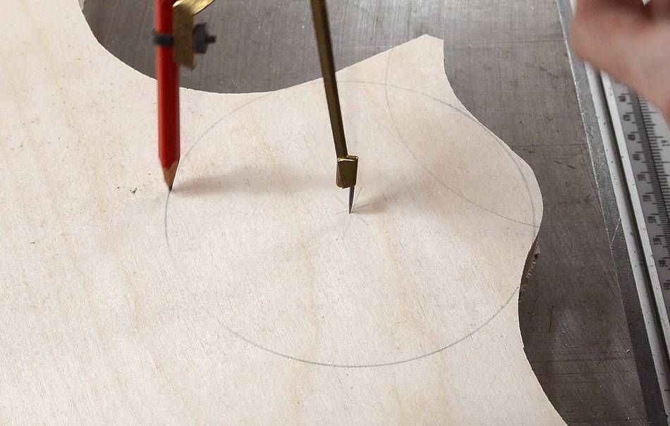
I started by drawing two circles on a scrap of Baltic birch plywood. I like to draw arcs from the edges to work out how close to the edge I can draw a circle.
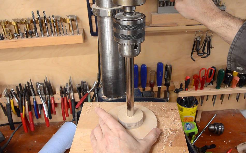
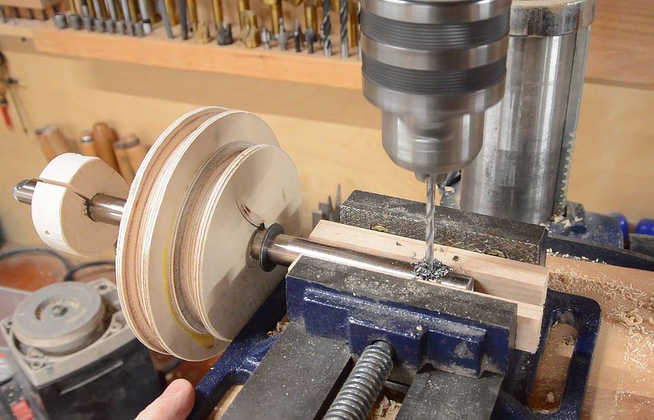
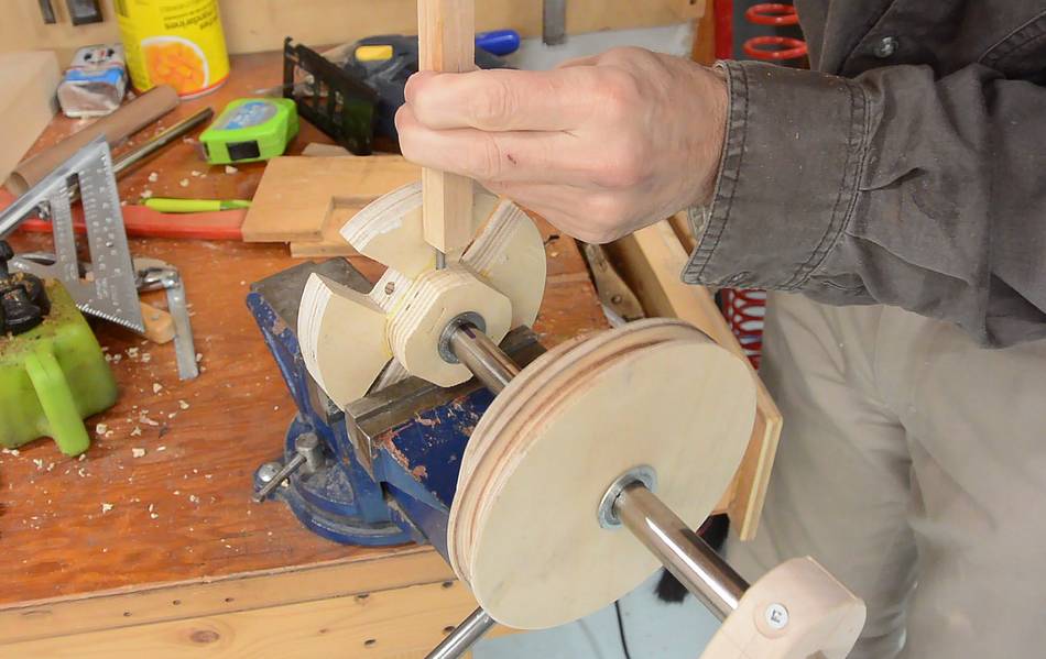
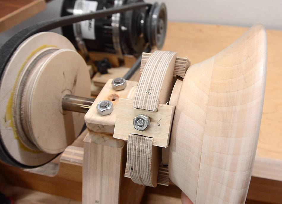
 This time I used my drill press to push the shaft into the holes. Then by
spinning the chuck I could make sure the disk was on flat, and didn't wobble
significantly, before clamping them together.
This time I used my drill press to push the shaft into the holes. Then by
spinning the chuck I could make sure the disk was on flat, and didn't wobble
significantly, before clamping them together.
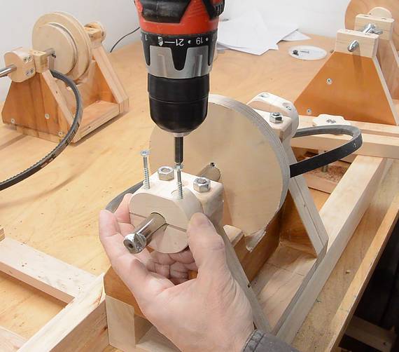
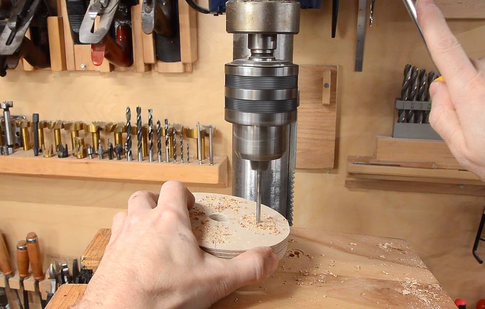 I drilled a series of holes around the disk for screwing a workpiece on.
These are at an angle to make it easier to screw them in.
I drilled a series of holes around the disk for screwing a workpiece on.
These are at an angle to make it easier to screw them in.
A normal faceplate is detached from the lathe when mounting the blank. But with this faceplate, the entire drive shaft and pulley is removed, and that pulley gets in the way. Screws at an angle make it easier to get the screwdriver in.
 I attached the faceplate with a pin, just like the chuck.
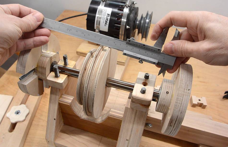
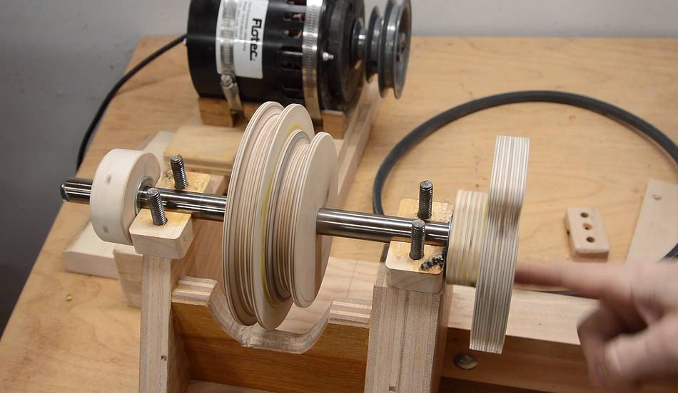
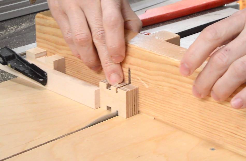
 I had about 8 mm of gap on the shaft. To avoid having the shaft move
side-to-side, I needed to make a spacer to go in this space.
I measured the gap,
cut a piece of wood to that thickness on the table saw, then made a spacer
and cut it in half.
I had about 8 mm of gap on the shaft. To avoid having the shaft move
side-to-side, I needed to make a spacer to go in this space.
I measured the gap,
cut a piece of wood to that thickness on the table saw, then made a spacer
and cut it in half.
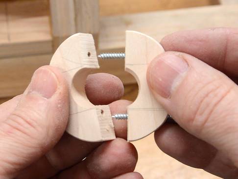
 That way, I could mount the spacer around the shaft without having
to slide it on from the end.
That way, I could mount the spacer around the shaft without having
to slide it on from the end.
I tried out the chuck by turning a small bowl with it — I will have
an article and video on that soon.
 Building a lathe
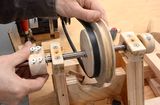 Lathe improvements
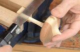 Making a spinning top
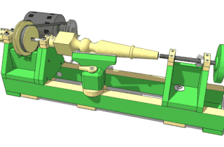 Buy the lathe plans
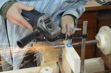 Grinding a machine taper with an angle grinder