 Since my AC motors article,
I have often been asked about how to reverse an AC induction motor.
I didn't cover how induction motors start in any detail earlier
because that's an extensive topic on its own.
Since my AC motors article,
I have often been asked about how to reverse an AC induction motor.
I didn't cover how induction motors start in any detail earlier
because that's an extensive topic on its own.
Since my AC motors article,
I have often been asked about how to reverse an AC induction motor.
I didn't cover how induction motors start in any detail earlier
because that's an extensive topic on its own.
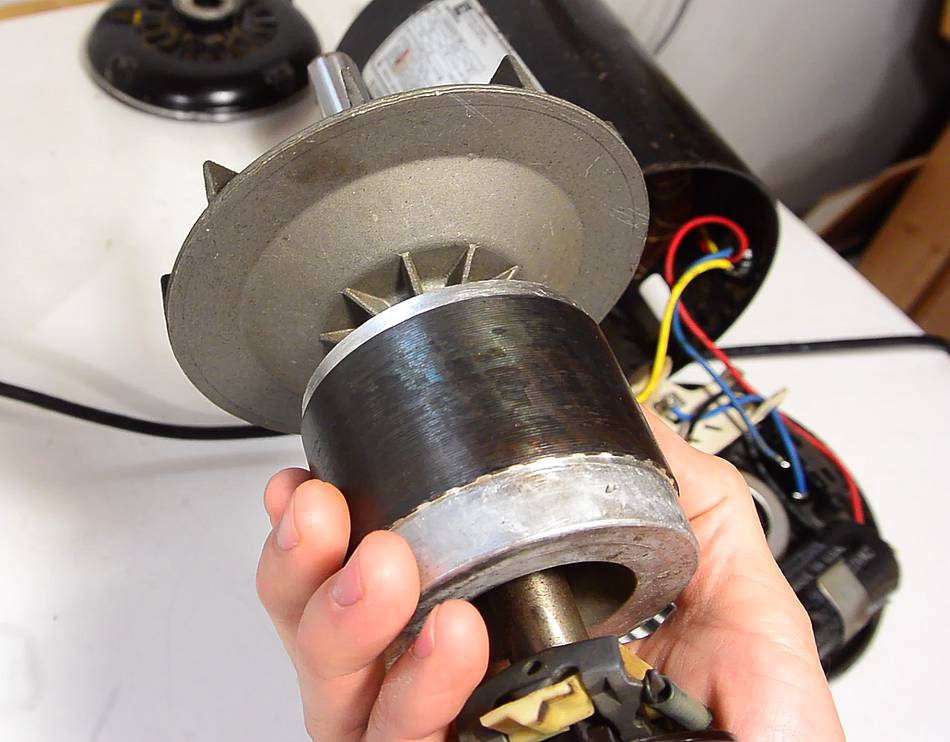
The rotor of an induction motor is essentially a permeable iron core with an aluminium short circuit winding cast in place. You can see the aluminium on both ends of the rotor. The aluminium also goes through lengthwise holes in the rotor to make a "squirrel cage" type short circuit winding. You can barely see lines, at a slight angle on the rotor where the windings pass through.
The short circuit winding causes the rotor to resist rapid changes in magnetic fields, so if it's subjected to a spinning magnetic field, it will try to follow it. (more on that here)
In a three phase motor, three phases on three windings naturally create a spinning magnetic field. But for single phase AC motors, the magnetic field only alternates back and forth. Some trickery is needed to create a rotating field.
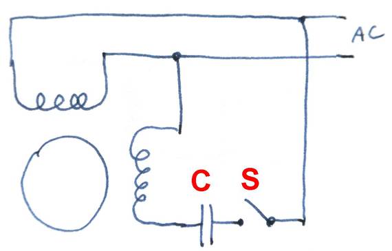
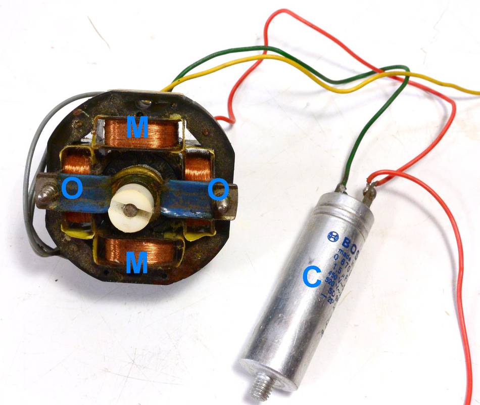 In this split phase motor, the main winding (label 'M')
is connected directly to 60 Hz AC power, while the
other winding (label 'O') is wired in series with a
capacitor (C). The interaction between the inductance of the motor
windings and the capacitor's capacitance causes that winding to be about 90
degrees out of phase with the main winding.
In this split phase motor, the main winding (label 'M')
is connected directly to 60 Hz AC power, while the
other winding (label 'O') is wired in series with a
capacitor (C). The interaction between the inductance of the motor
windings and the capacitor's capacitance causes that winding to be about 90
degrees out of phase with the main winding.
With the main winding creating a magnetic field that alternates vertically,
and the other winding creating a magnetic field that alternates horizontally
but out of phase, the sum of these is a spinning magnetic field.
The rotor tries to follow it, causing it to spin.
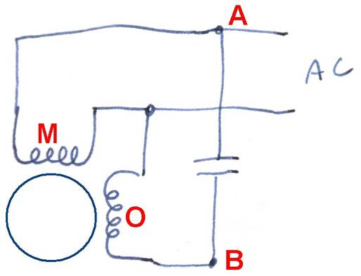
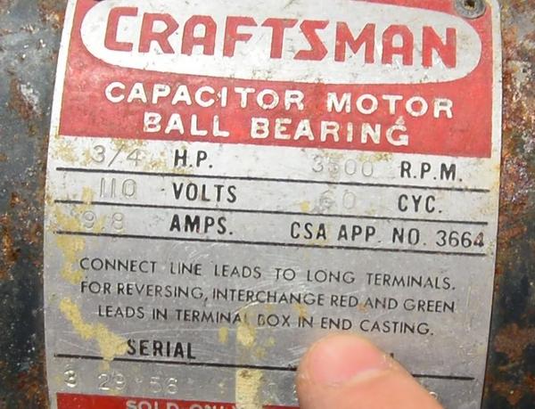
Reversing the motor is simply a matter of moving the power connection
so that the other winding is directly on AC. Essentially, moving
one side of the power connection from (A) to (B), causing winding (O)
to be the main winding and winding (M) to be the phase shifted one.
On motors larger than 1/4 hp, the two windings typically have different numbers of turns, so this method of reversing may not be applicable. Check that the resistance of the two windings is the same first.
If the windings are not the same resistance, you can still reverse it by reversing the polarity of one of the windings, provided that the windigs are not tied together inside the motor (as in, more than three wires coming out from the windings).
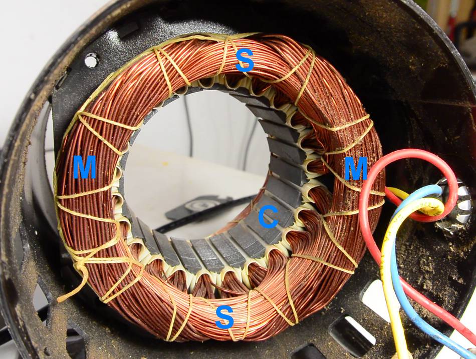 Now, if we look inside a bigger motor, like this 3/4 horsepower motor,
the windings look
much more complicated. The windings are spread across many slots
in the motor's stator (C). That way, there
is less of an abrupt change from one pole to the next. This
makes for a smoother magnetic field, which makes for a quieter, more
efficient motor.
Now, if we look inside a bigger motor, like this 3/4 horsepower motor,
the windings look
much more complicated. The windings are spread across many slots
in the motor's stator (C). That way, there
is less of an abrupt change from one pole to the next. This
makes for a smoother magnetic field, which makes for a quieter, more
efficient motor.
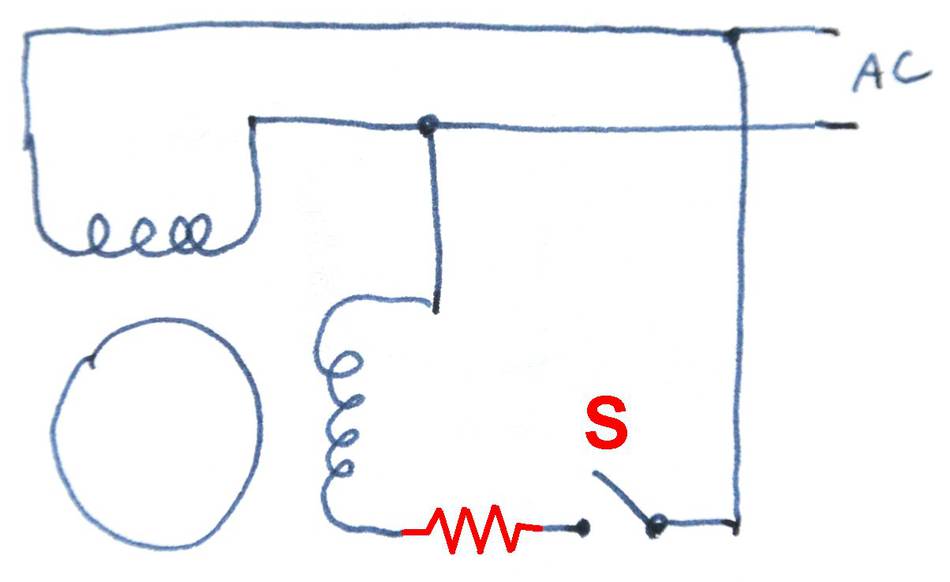
This motor has a thick main winding (M), plus a starter winding
made of thinner wire (S). The main winding creates a horizontal
magnetic field, while the starter winding creates a vertical one.
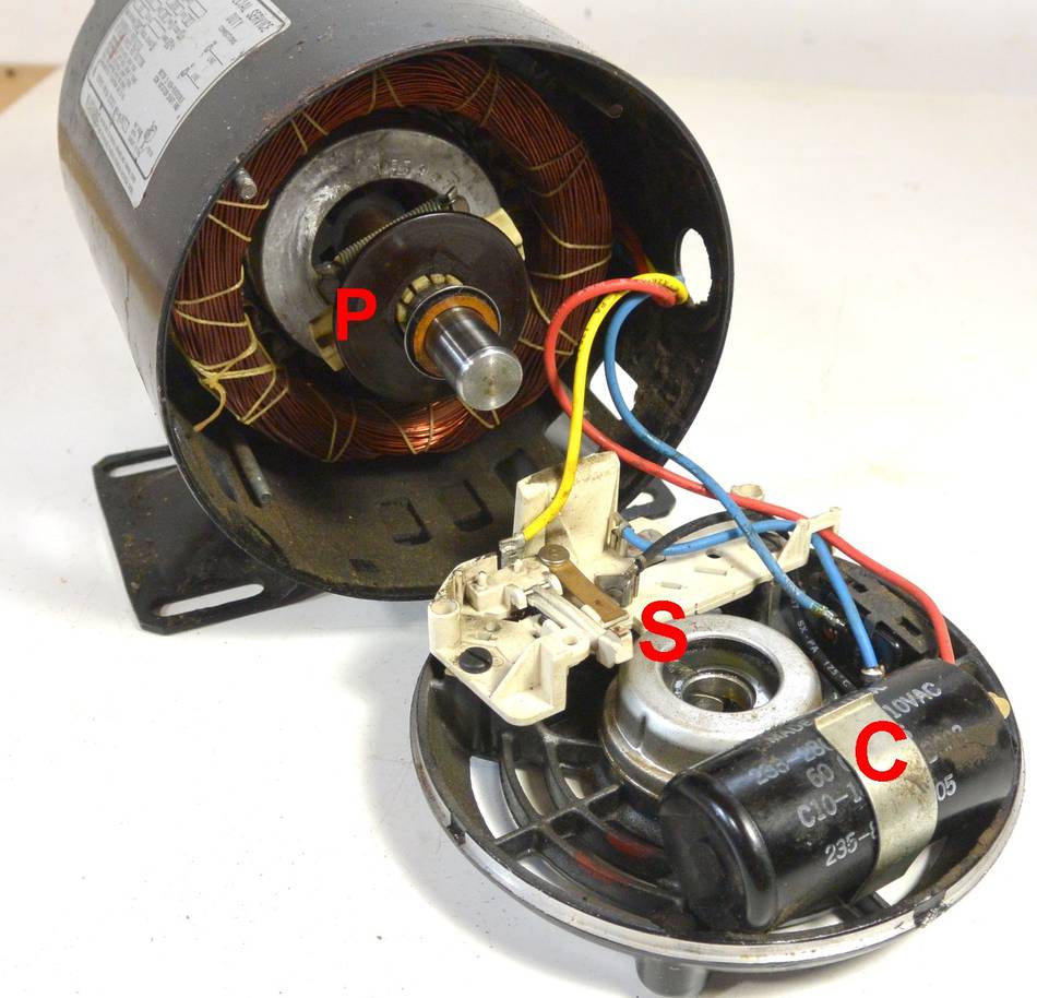
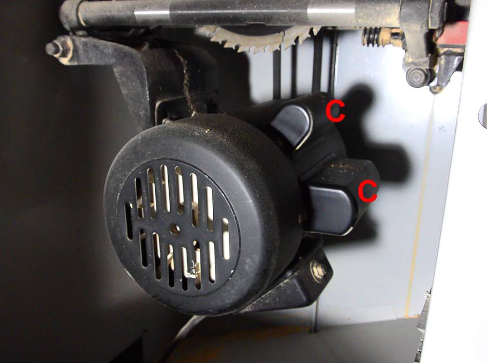
 This starter winding is in series with a capacitor (C), and a centrifugal
switch (S). In this motor, the starter capacitor is mounted
inside the main housing. More typically, the starter capacitor is mounted
on top of the housing under a metal dome.
This starter winding is in series with a capacitor (C), and a centrifugal
switch (S). In this motor, the starter capacitor is mounted
inside the main housing. More typically, the starter capacitor is mounted
on top of the housing under a metal dome.
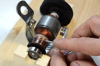
The centrifugal switch (S) is mounted to the back plate and is activated by a disk (P) that pushes against a tab on the switch (just left of the S in the photo).
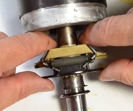
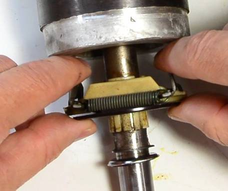 Removing the rotor and looking at the disk, you can see two metal tabs.
When the motor spins, centrifugal force pushes these outwards, which
in turn pulls the disk back. This releases the plastic tab on the switch,
causing the switch to open and the starter winding to be disconnected.
The disk pulls back far enough that it's no longer in contact
with the tab, minimizing friction and wear. It's a clever way to
activate a switch based on centrifugal force without the need for the
switch itself to spin.
Removing the rotor and looking at the disk, you can see two metal tabs.
When the motor spins, centrifugal force pushes these outwards, which
in turn pulls the disk back. This releases the plastic tab on the switch,
causing the switch to open and the starter winding to be disconnected.
The disk pulls back far enough that it's no longer in contact
with the tab, minimizing friction and wear. It's a clever way to
activate a switch based on centrifugal force without the need for the
switch itself to spin.
The centrifugal switch arrangement makes a distinct "click" when it resets after the motor is shut off. The click of the switch engaging as it starts up is much harder to discern.
 If the starter winding helps the motor start, it would surely help
the motor run as well. So why not just leave the starter
winding connected? Well, the
whole phase shift thing is not that elegant. The size of capacitor you
need very much depends on the motor's load. To start the motor quickly,
you need a larger capacitance than you would for efficient continuous
operation. Also, the capacitor is an electrolytic capacitor, and isn't
designed for continuous load. And because the starter winding is only
used briefly, so it's made of thinner wire to save money, because
copper is expensive.
If the starter winding helps the motor start, it would surely help
the motor run as well. So why not just leave the starter
winding connected? Well, the
whole phase shift thing is not that elegant. The size of capacitor you
need very much depends on the motor's load. To start the motor quickly,
you need a larger capacitance than you would for efficient continuous
operation. Also, the capacitor is an electrolytic capacitor, and isn't
designed for continuous load. And because the starter winding is only
used briefly, so it's made of thinner wire to save money, because
copper is expensive.
There are some motors that use a big capacitor for starting and a smaller capacitor for continuous operation. Such motors often have two externally mounted capacitors (C), as seen on this one in my table saw. These motors are called "capacitor start capacitor run" motors. Capacitor start capacitor run motors are typically more than one horsepower. This one is 1.75 horsepower.
This results in much less phase shift than with a capacitor, but enough to get the motor running. The windings of the motor essentially form an inductor, and when an AC sine wave (as in, AC power) is applied to an inductor, the current lags the voltage by 90 degrees. And the magnetic field is strictly a function of current.
For a resistor, the current is in phase with the voltage. If we had a large resistance and small inductance in series, the voltage drop, and current would be largely determined by the resistor. So the current and magnetic field would be largely in phase with the applied voltage. With current in the main winding lagging by 90 degrees, we would have a 90-degree difference between the two, but the starter winding would be extremely inefficient.
In reality, the compromise is for much less
of a phase shift and more power. It's enough to get the motor running.
Regardless, the starter on these motors is quite inefficient, but it
doesn't matter much once the motor is running. However, the extra current
required for the starter could blow a circuit breaker, so this method
is typically only used for smaller motors, 1/4 hp to 1/2 hp.
3/4 horsepower or larger motors typically use a starting capacitor.
If you are not familiar with analog electronics, the above explanation is probably inadequate, and you may want to read up more on induction motors if you don't understand it.
With induction motors, the only things that wear out are the bearings, the starter switch and the capacitor. With no capacitor, there's one less thing to fail.
Just recently, I accidentally jammed the starter switch on a 1/4 hp resistive start motor from a clothes dryer (the one on this blower) and it only took about 15 seconds for the motor to trip its thermal protection circuit because the starter winding overheated.
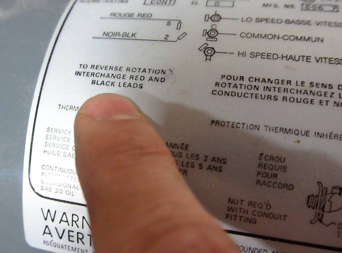
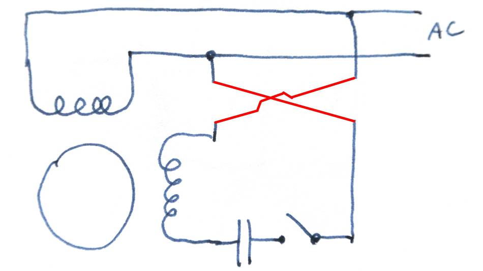 So how do we reverse a capacitor start motor? Once started,
a single phase induction
motor will happily run in either direction. To reverse it, we need to
change the direction of the rotating magnetic field produced by the main
and starter windings. And this can be accomplished by reversing the
polarity of the starter winding. Basically, we need to swap the
connections on either end of the starter winding. Sometimes it's
just the winding, Sometimes the winding, switch and capacitor are
reversed. The order of the switch and capacitor don't
matter, as long as thy are in wired in series.
So how do we reverse a capacitor start motor? Once started,
a single phase induction
motor will happily run in either direction. To reverse it, we need to
change the direction of the rotating magnetic field produced by the main
and starter windings. And this can be accomplished by reversing the
polarity of the starter winding. Basically, we need to swap the
connections on either end of the starter winding. Sometimes it's
just the winding, Sometimes the winding, switch and capacitor are
reversed. The order of the switch and capacitor don't
matter, as long as thy are in wired in series.
You could also reverse the motor by reversing the main winding (same effect).
If you were to switch the main and starter windings, as one does with a split phase motor, the motor will also reverse. However, it will not run at full power and is also likely to burn out. The starter winding is not suitable for continuous operation.
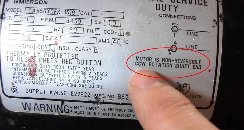 The label on this motor indicates "MOTOR IS NON-REVERSIBLE".
If you look at the previous pictures of this motor, you can see there are only three wires (red, yellow and blue) coming out from the windings. One end of the main and starter windings is connected together right on the windings.
To reverse the starter winding, I'd have to break that connection inside the windings and bring out the other end of the starter winding. But I really can't get at it because of the way it's inside the motor. I'd have to cut a hole in the enclosure to even get at the point where they are tied together. It's not that this motor can't be reversed, just that, as a cost saving measure, they made reversing it more difficult than is worth the trouble.
But on motors that are reversible, the label always indicates to swap two wires to reverse it.
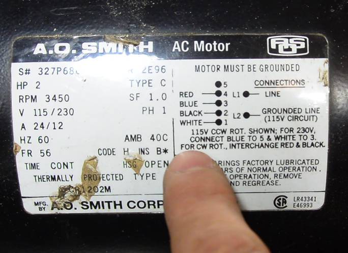
If you have a motor where the label is missing, the starter winding typically has about three times the electrical resistance of the main winding and is always in series with the starter switch and capacitor (if there is one). If you can isolate both ends of this winding and swap them, you can reverse the motor. If however there are only three wires coming out of the windings, then the main and starter windings have one end tied together and the motor is not reversible.
For a 1/2 hp 120 volt motor, the main winding will typically have about 1.5 ohms, and the starter winding about 4 ohms. For 240 volt 1/2 hp motors (240 volt only), you should expect abot 6 ohms on the main winding, and 16 ohms on the starter winding. Expect the resistance of the windings to be inversely proportional with horsepower.
A lot of motors will have a few extra wires coming off the windings. Often, a thermal switch is attached to the windings, and this switch may be partially tied to one of the windings. Also, if the motor can be rewired for 120 and 240 volt, the main winding will consist of two 120 volt windings that can be wired either in series or parallel. So there can be quite a few wires coming off the windings. It can take a bit of time and probing around to figure it out.
For motors that can be wired at both 120 volts and 240 volts, the starter winding is a 120 volt winding. When these motors are wired for 240 volts, the main winding is used as an autotransformer to make the 120 volts for the starter winding. Otherwise, rewiring the motor from 120 to 240 volts would be much more complex!
 How DC motors work (2014)
 Photographing airborne dust (2012)
 Are link belts worth it? (2014)
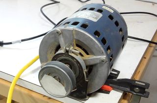 How AC (induction) motors work
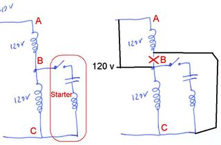 Switching motors between 240 and 120 volts
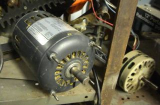 Where do you get your motors from?
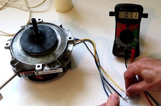 Figuring out a mystery motor
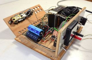 Homemade benchtop power supply
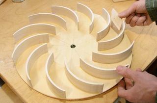 Building a dust collector blower
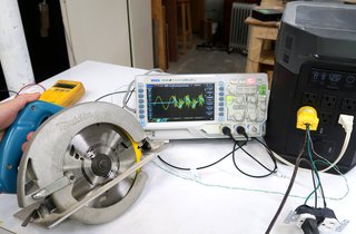 Inverters don't like power tools