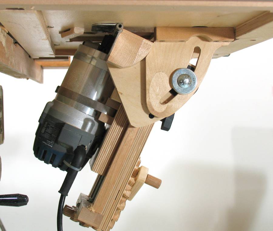
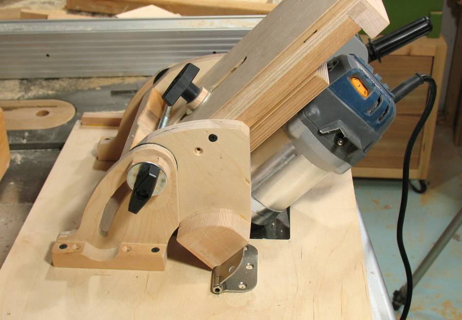
 What makes this router lift a "tilting" router lift is the tilting mount
for the sliding mechanism.
What makes this router lift a "tilting" router lift is the tilting mount
for the sliding mechanism.
What makes this router lift a "tilting" router lift is the tilting mount
for the sliding mechanism.
The tilting mechanism is really quite a simple affair, consisting of a set of hinges on either side of the router, and brackets for locking the tilt angle in place.
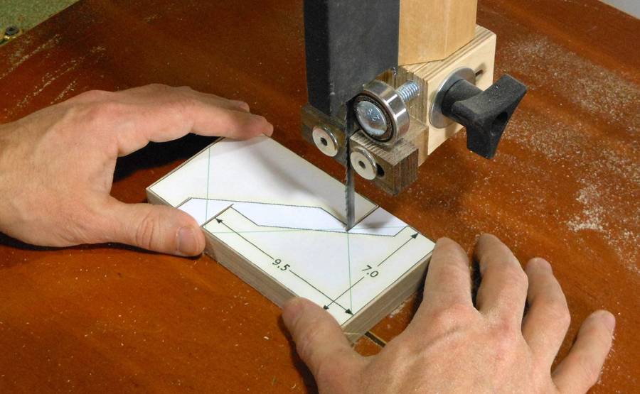
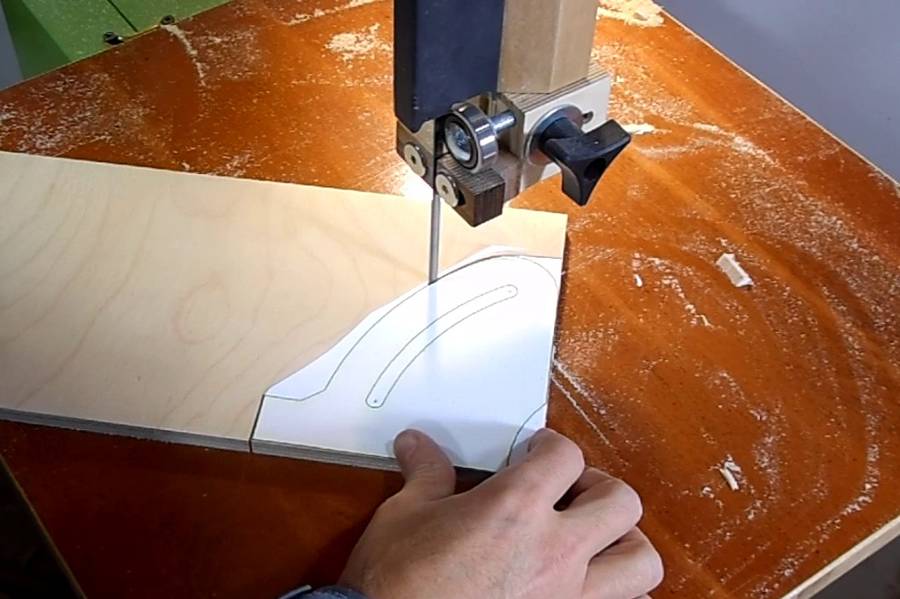 I start by cutting the parts out on the bandsaw using 1:1 printouts from the CAD model.
I used a scroll saw to cut out the curved slot in the tilt lock, but a jigsaw, or a series of overlapping holes would also work.
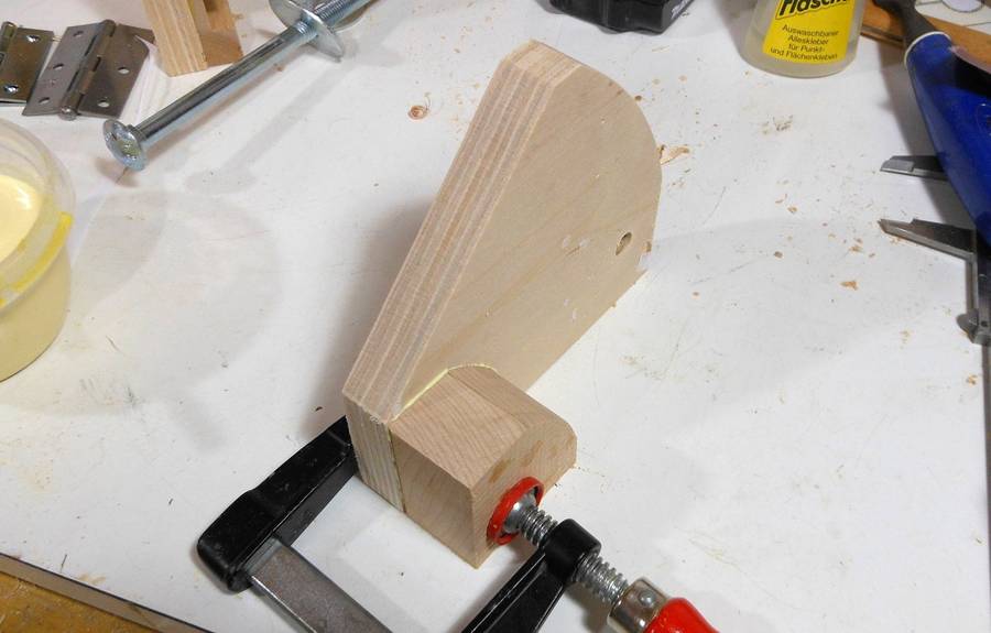 Here's one of the "flanges" that the hinge will mount to.
It's made out of 18 mm birch plywood (about 3/4" thick)
A block needs to be glued to one end of it to provide more room to
attach the hinge.
Here's one of the "flanges" that the hinge will mount to.
It's made out of 18 mm birch plywood (about 3/4" thick)
A block needs to be glued to one end of it to provide more room to
attach the hinge.
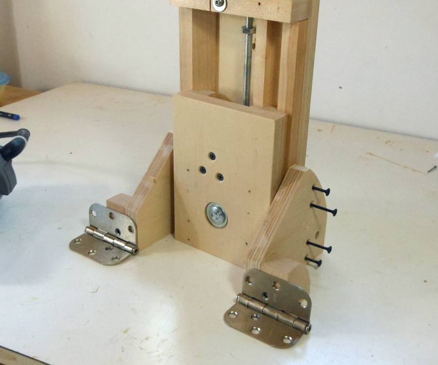 Checking the selected hinges. These are 3" (75 mm) wide hinges. A bit wider
than the mounts, but most smaller hinges are made from much thinner metal.
I found some 2.5" hinges that were also fairly sturdy, but they were
more expensive than the very common 3" door hinges.
Checking the selected hinges. These are 3" (75 mm) wide hinges. A bit wider
than the mounts, but most smaller hinges are made from much thinner metal.
I found some 2.5" hinges that were also fairly sturdy, but they were
more expensive than the very common 3" door hinges.
I drilled some extra holes in the hinges because otherwise I could only use two holes against the flanges. After drilling the hole, I used the tip of a larger (3/8" or 10 mm) drill to cut a countersink in the hinge.
![]() The part around the pin of the door hinge is a bit thicker than the rest of the
hinge, so a relief needs to be cut on the mounting flanges and on the table bottom.
Here I had just chiseled that relief cut into the bottom of the table.
The part around the pin of the door hinge is a bit thicker than the rest of the
hinge, so a relief needs to be cut on the mounting flanges and on the table bottom.
Here I had just chiseled that relief cut into the bottom of the table.
The table is 18 mm (3/4") Baltic birch plywood.
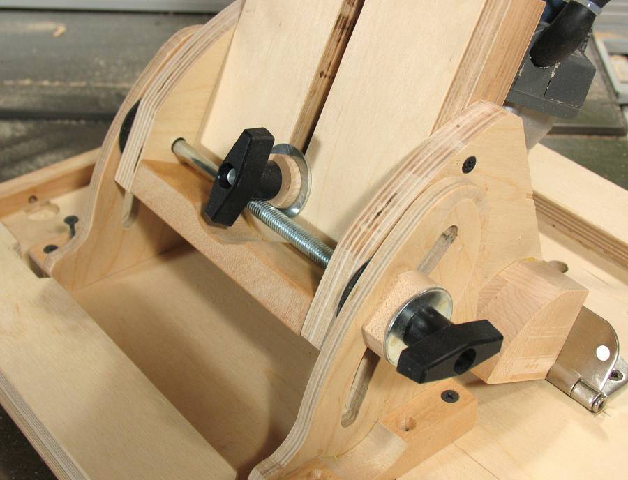 A threaded rod goes all the way across the mount, so that one knob can
tighten the flanges on both sides. I initially used an 8" long carriage bolt,
and you can see that bolt in some of the pictures.
I could only get a bolt that long as a 3/8" bolt. I later swapped the bolt
for a 25 cm long piece of 5/16" (M8) threaded rod, seeing that there was threaded
rod left over from the lift mechanism anyway. I figure that will make shopping
for the screws and such for this project a little easier.
A threaded rod goes all the way across the mount, so that one knob can
tighten the flanges on both sides. I initially used an 8" long carriage bolt,
and you can see that bolt in some of the pictures.
I could only get a bolt that long as a 3/8" bolt. I later swapped the bolt
for a 25 cm long piece of 5/16" (M8) threaded rod, seeing that there was threaded
rod left over from the lift mechanism anyway. I figure that will make shopping
for the screws and such for this project a little easier.
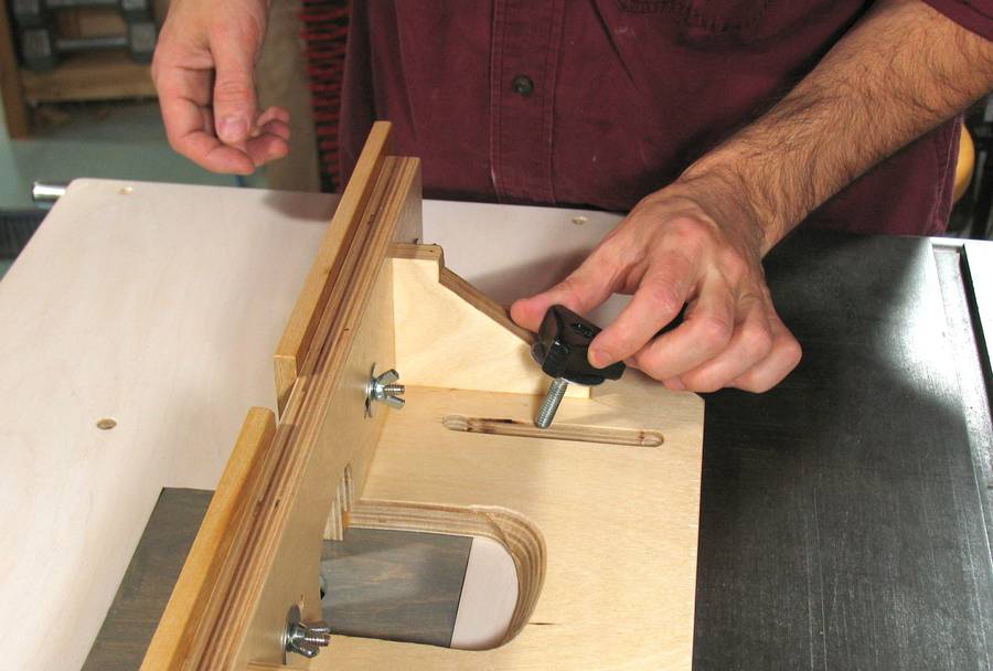
Space is very tight around that threaded rod, and I had to put a spacer between the plastic knob and the washer so that the T-bar of the knob would clear the threaded rod.
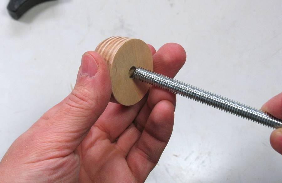 It's best to have a disk firmly attached to one end of the threaded rod.
I did this by just drilling a
slightly undersized hole in a plywood disk and then twisting that onto the
end of the rod. I had to hold the threaded rod in the vise while I twisted on
that disk. It holds quite well, but if you aren't fully confident in how the
threads hold in wood, you could always add a nut behind the plywood disk.
It's best to have a disk firmly attached to one end of the threaded rod.
I did this by just drilling a
slightly undersized hole in a plywood disk and then twisting that onto the
end of the rod. I had to hold the threaded rod in the vise while I twisted on
that disk. It holds quite well, but if you aren't fully confident in how the
threads hold in wood, you could always add a nut behind the plywood disk.
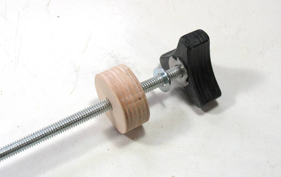 I didn't have any 5/16" bar knobs handy, so I made a wooden knob similar to the ones
I made for the fence, but 10% bigger. A T-nut
pressed into the knob provides the thread. This lift already uses several 5/16" (M8)
T-nuts in other places. The plywood disk
in this picture fits loosely on the threaded rod (unlike the one in the previous picture)
I didn't have any 5/16" bar knobs handy, so I made a wooden knob similar to the ones
I made for the fence, but 10% bigger. A T-nut
pressed into the knob provides the thread. This lift already uses several 5/16" (M8)
T-nuts in other places. The plywood disk
in this picture fits loosely on the threaded rod (unlike the one in the previous picture)
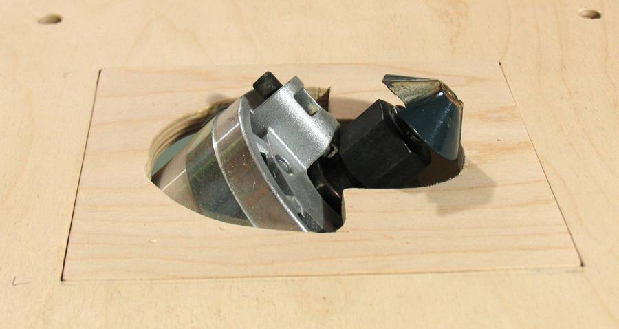
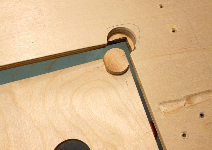
 When tilted the full 45-degrees the router comes close to touching the
edge of the hole in the table. In fact, the hole is actually 2 cm wider in that direction
to better accommodate the router body.
When tilted the full 45-degrees the router comes close to touching the
edge of the hole in the table. In fact, the hole is actually 2 cm wider in that direction
to better accommodate the router body.
 Tilted 45 degrees and all the way up, part of the router body will
protrude above the table. This can be a useful configuration for some cuts.
Tilted 45 degrees and all the way up, part of the router body will
protrude above the table. This can be a useful configuration for some cuts.
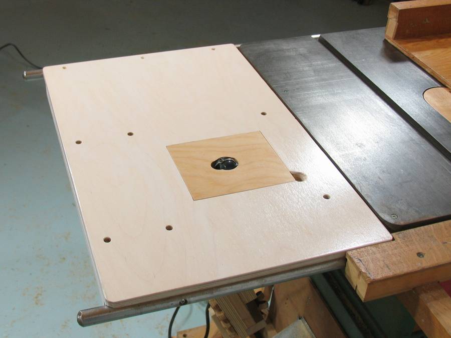 The router table top is made of 3/4" Baltic birch plywood. The router lift is mounted to
the bottom of it, and a rectangular insert is inserted from the top.
The router table top is made of 3/4" Baltic birch plywood. The router lift is mounted to
the bottom of it, and a rectangular insert is inserted from the top.
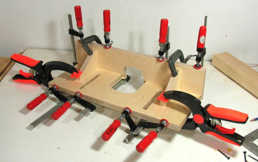
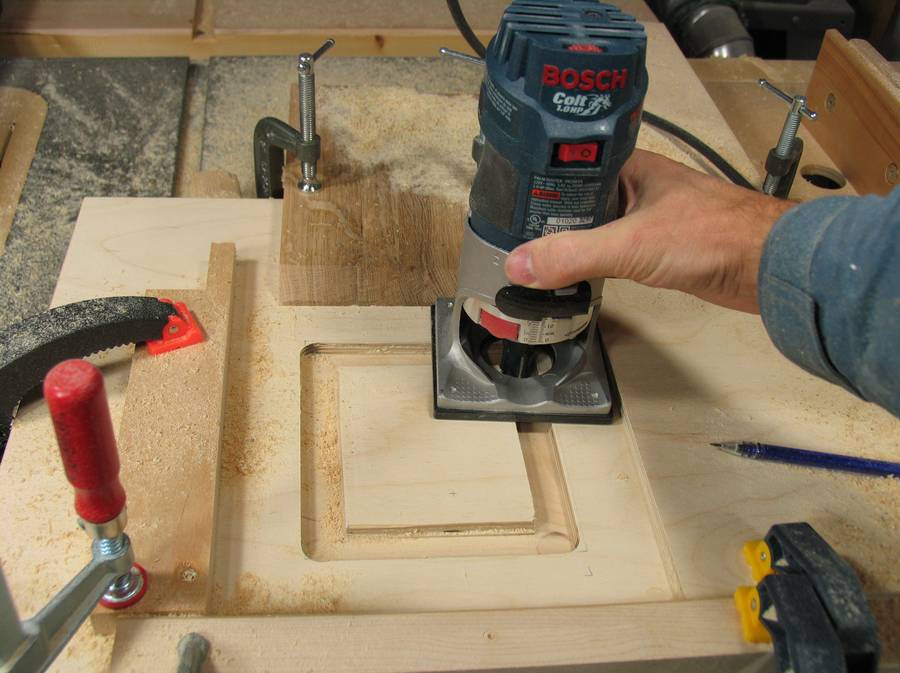 A rectangular opening needs to be cut into the plywood for the insert. I clamped
four pieces of wood to the plywood to act as guides for routing the rectangle.
A rectangular opening needs to be cut into the plywood for the insert. I clamped
four pieces of wood to the plywood to act as guides for routing the rectangle.
I start with a 3/4" (19 mm) square cutter. The guides are placed such that this cutter will cut to the line that marks where the 13x15 cm opening will be.
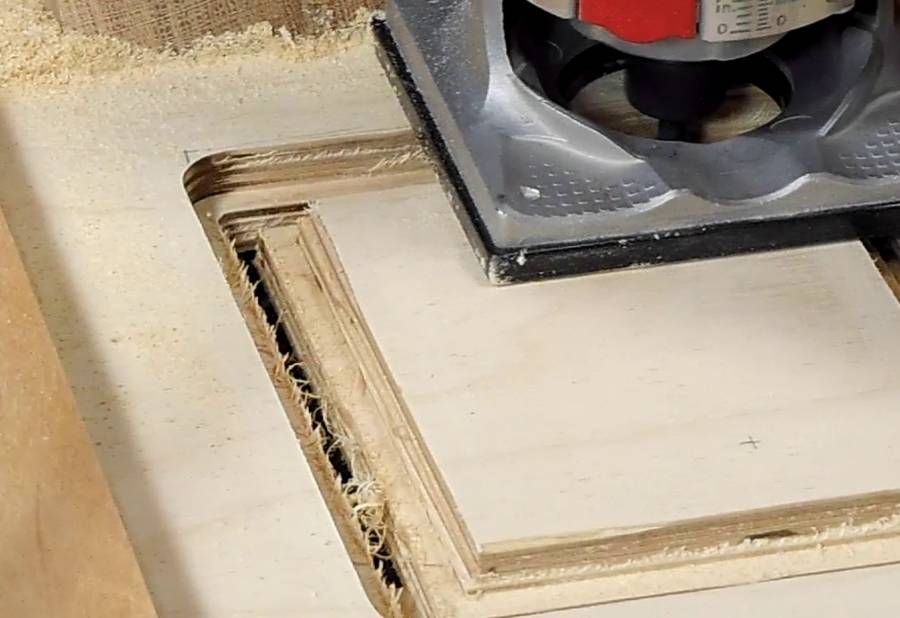 Next switching to a 1/4" (6 mm) wide cutter, but leaving the guides in place,
I cut successively deeper until I cut all the way
through the plywood. This leaves an opening with a 1/4" or 6 mm ledge all around.
Next switching to a 1/4" (6 mm) wide cutter, but leaving the guides in place,
I cut successively deeper until I cut all the way
through the plywood. This leaves an opening with a 1/4" or 6 mm ledge all around.
 The router motor blows lots of air out the front, and this has a
tendency to lift up the insert.
I added a tab to one corner of the insert, which hooks below the table.
The router motor blows lots of air out the front, and this has a
tendency to lift up the insert.
I added a tab to one corner of the insert, which hooks below the table.
 I attached a rare earth magnet to the bottom of the table in the opposite corner as the tab.
The magnet attracts a screw in the insert to hold it down.
I attached a rare earth magnet to the bottom of the table in the opposite corner as the tab.
The magnet attracts a screw in the insert to hold it down.
On my previous router lift, I just used a regular door catch magnet, but because this router lift tilts, there wasn't enough room for one of those.
I used a magnet that I reclaimed out of an old hard disk - this saved making a trip to Lee Valley Tools to buy the magnet.
Between the tab in one corner and the screw and magnet in the other, it's enough to hold the insert down against the air blown out of the router.
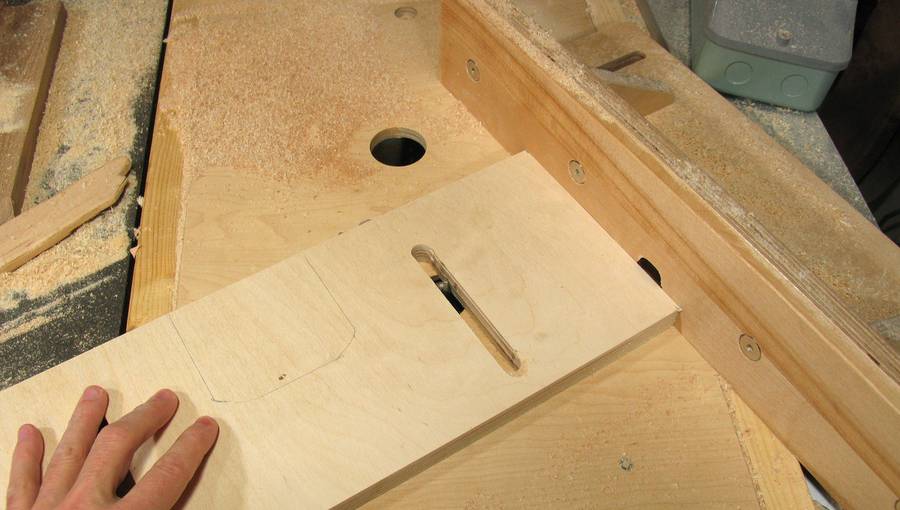 The fence has two slots that allow it to be clamped in different positions.
I'm using my other router lift to cut this slot. But you could rig up a temporary
fence to use the router lift you are building to cut this slot.
The fence has two slots that allow it to be clamped in different positions.
I'm using my other router lift to cut this slot. But you could rig up a temporary
fence to use the router lift you are building to cut this slot.
 All the fence parts were cut using paper templates.
 Next gluing the pieces together. On gluing, everything is just butt joints.
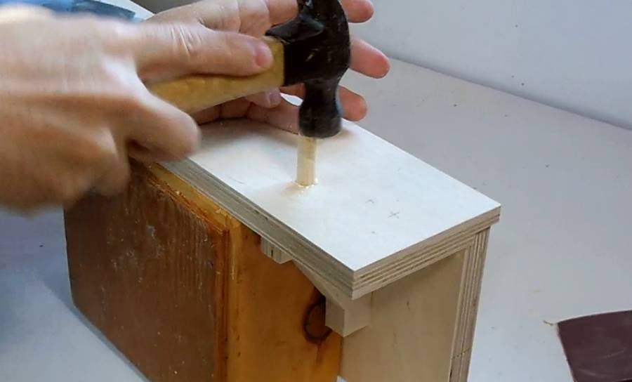 The gussets are doweled through. So after the glue has dried, I drill a 3.5 cm deep
3/8" (10 mm) hole from the faces into the gusset
and then glue in a dowel from the sides. The dowels are cut slightly longer than needed.
After gluing, I cut them flush with a chisel.
See here for more on that.
The gussets are doweled through. So after the glue has dried, I drill a 3.5 cm deep
3/8" (10 mm) hole from the faces into the gusset
and then glue in a dowel from the sides. The dowels are cut slightly longer than needed.
After gluing, I cut them flush with a chisel.
See here for more on that.
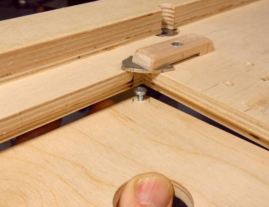
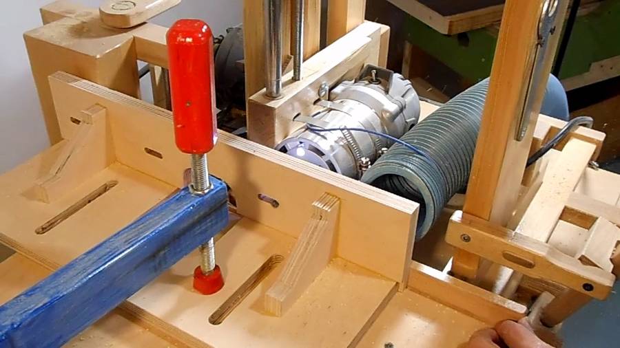 Cutting the slots for mounting the adjustable fence panels to the front.
I could have cut these on the router table as well, but it was easier to do with my slot mortiser
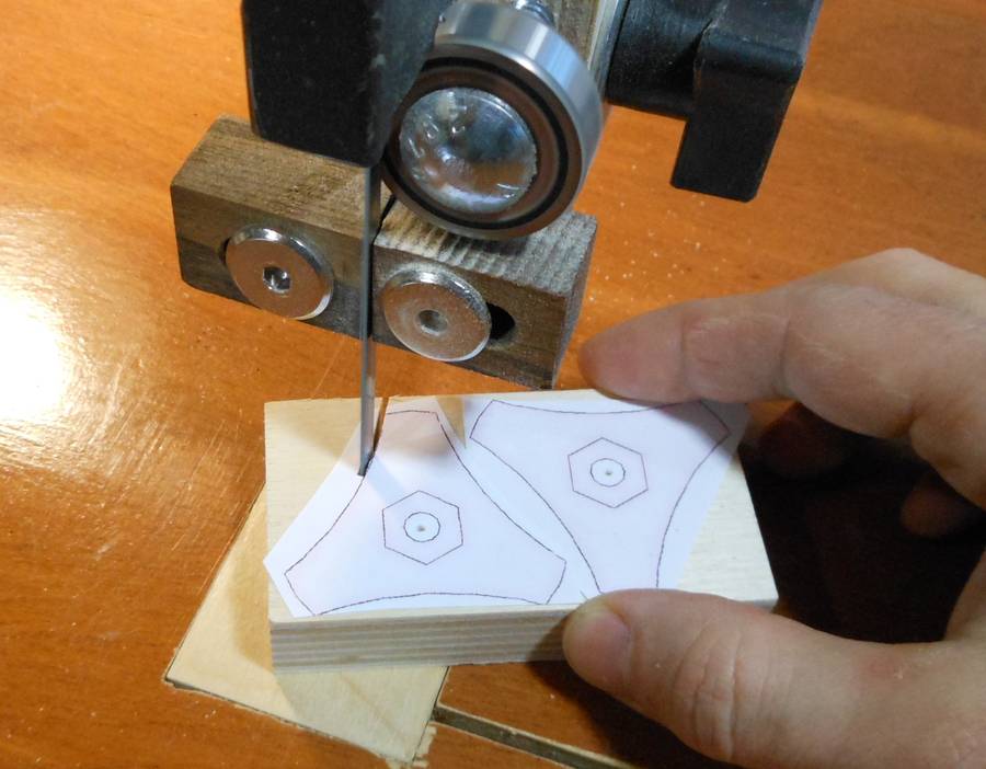 Next making the screw knobs for holding down the fence. Again, I start with a paper template.
I drilled a hole just smaller than the bolt head in the top of the knobs, about 8 mm deep, with another hole the exact same size as my bolt all the way through. Next I chisel the opening to be hexagonal for the bolt head, but slightly smaller. I marked that hexagon by inserting the bolt into the hole, then hitting the head with a hammer to leave a hexagonal impression in the wood.
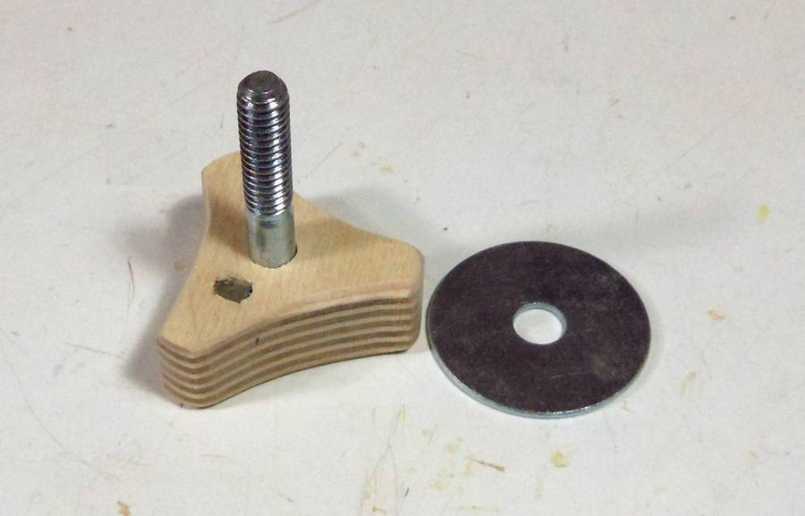 Finished knob with bolt in it. I also drilled a small hole in the bottom of the knob,
and inserted a small rare earth magnet in that hole.
Finished knob with bolt in it. I also drilled a small hole in the bottom of the knob,
and inserted a small rare earth magnet in that hole.
 The idea of the magnet is that it holds the washer in place. That way, when I remove the knobs,
the washers stay with the knobs. I also painted the knobs black.
The idea of the magnet is that it holds the washer in place. That way, when I remove the knobs,
the washers stay with the knobs. I also painted the knobs black.
Next: Making modling with the tilting router lift
Back to the tilting router lift