Andrew Scott's tilting router lift
Andrew Scott writes:
Hi Matthias,
Here are some pictures of my modified tilt router lift. I hope my wife's checkered table cloth doesn't cause too much of a moiré pattern on your screen.
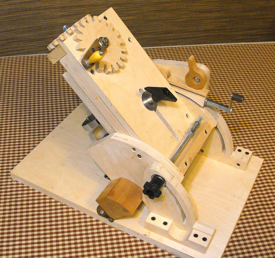
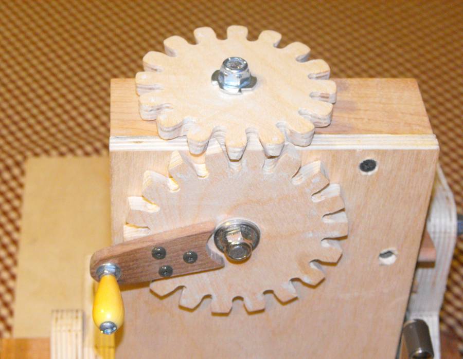 The first obvious change is the 18:16
gearing. I'm quite comfortable
with metric, imperial or decimal inches but the 16 turns per inch is
real convenient for me with 64ths available with a quarter turn.
The first obvious change is the 18:16
gearing. I'm quite comfortable
with metric, imperial or decimal inches but the 16 turns per inch is
real convenient for me with 64ths available with a quarter turn.
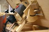
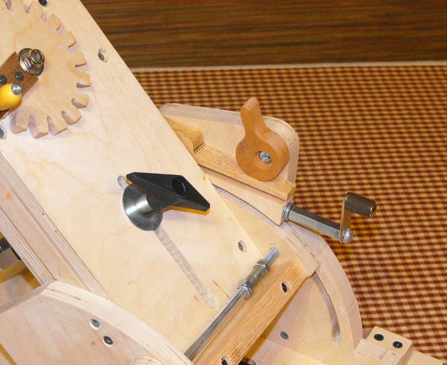 The next easily visible addition is the angle crank. The angle crank
turns a 1/4 by 6 in. lag bolt "worm gear" that advances the angle one
crank per degree. This feature is really important for me. I looked at
1/4, 5/16 and 3/8 in. screws but the 10 tpi of the 1/4 worked out the
best to keep the quadrant radius close to your design. I got lucky with
my math and bandsaw work; the full 45 degrees is exactly 45 cranks.
The next easily visible addition is the angle crank. The angle crank
turns a 1/4 by 6 in. lag bolt "worm gear" that advances the angle one
crank per degree. This feature is really important for me. I looked at
1/4, 5/16 and 3/8 in. screws but the 10 tpi of the 1/4 worked out the
best to keep the quadrant radius close to your design. I got lucky with
my math and bandsaw work; the full 45 degrees is exactly 45 cranks.
I wanted the ability for quick setting so a cam engages the worm by pressing on an oak spring that forces the worm into the trunnion. Releasing the cam allows for a quick set.
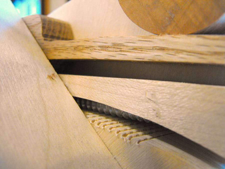 The trunnion threads are created by
temporarily marking the quadrant with another lag bolt. The bolt is just
tapped with a hammer to leave a thread impression. Teeth are shallowly
cut with a bandsaw at the appropriate angle. It's easier to do this at
the back of the saw, pulling the stock towards you.
The trunnion threads are created by
temporarily marking the quadrant with another lag bolt. The bolt is just
tapped with a hammer to leave a thread impression. Teeth are shallowly
cut with a bandsaw at the appropriate angle. It's easier to do this at
the back of the saw, pulling the stock towards you.
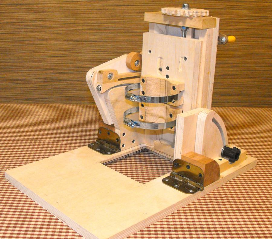
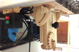
The worm gear construction is a bit fiddly but seems to work well. The worm is housed in a block of maple with an arch cut out to expose the threads to the trunnion. To make the worm I first cut the head off the lag bolt. Then the bolt is chucked in a drill and 1/2 in. of the pointy end is ground down with a bench grinder to 3/16 of an inch. I threaded the end with a 10-24 die and about a 1/2 inch of the head end with a 1/4 x 20 die. The 3/16 end is held in place in the worm block with an old router bit bearing, 1/2" O.D. x 3/16" I.D. The bearing is countersunk into the end of the maple block with a forstner bit and is held in place with a lock nut. The lag bolt passes through a 1/4 in. hole in the block and the 1 in. of the clear shank that's left glides pretty smoothly in the maple.
 The crank is extended with a store bought
rod coupler and I bolted an old pencil sharpener crank on the end.
The crank is extended with a store bought
rod coupler and I bolted an old pencil sharpener crank on the end.
Other minor changes are double bearings in the gearing and lifting rod. I realize that roller skate bearings aren't thrust bearings but there is little axial pressure put on them, just snug. If they're left proud a hair it aids clearance as well. I liked your idea of a long carriage bolt to tighten the angle but, like you, I couldn't find one. Maybe they don't make longer ones? Anyway, I made my own coupler by threading the inside of a piece of light fixture hardware. It's a bit of a pain to assemble and disassemble but hopefully I won't need to do that much.
Matthias comments:
I was able to find an 8" (20 cm) long 3/8" carriage bolt at The Home Depot,
but it was a bit bulky. Then I realized I could eliminate that part
by just using the leftover 5/16 (or M6) threaded rod from the lift mechanism
for the angle clamp.
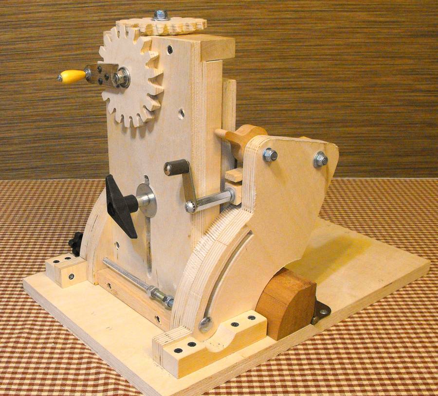
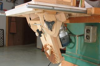
 The tilt router lift is now happily in my workshop and my wife
is happy it's off the dinner table. I threatened that if I could find
a couple places to put candles, it's pretty enough to be a
centerpiece.
The tilt router lift is now happily in my workshop and my wife
is happy it's off the dinner table. I threatened that if I could find
a couple places to put candles, it's pretty enough to be a
centerpiece.
One other benefit of gearing the angle selector that I came across was that when you dry fit an angled router cut joint and you need to tweak it a fraction of a degree, even with a bit of backlash it's pretty easy to adjust by a fraction of a degree -- possibly even to the eighth.
Andrew Scott
See also:

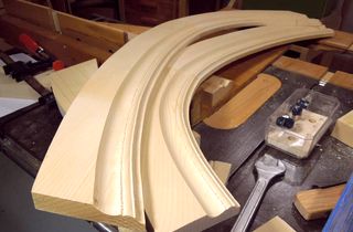 Making curved molding