 The base of the machine is 1-inch thick plywood.
On this base I mounted two slides to go side to side, and a piece of 3/4"
thick birch plywood on top of those sliders.
The base of the machine is 1-inch thick plywood.
On this base I mounted two slides to go side to side, and a piece of 3/4"
thick birch plywood on top of those sliders.
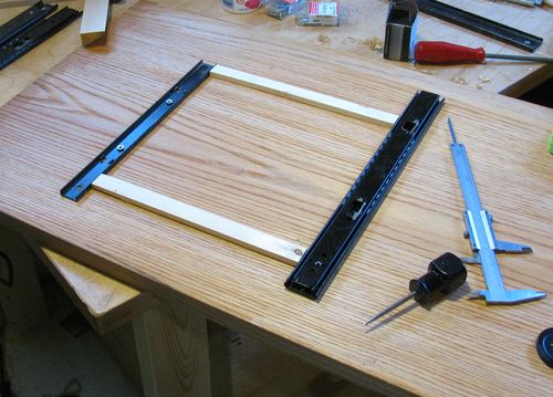
Next I considered using telescoping full extension ball bearing drawer slides, but these just weren't "tight" enough. Measuring deflection with a dial indicator while pushing down on them showed that they had a fair bit of play. This play is to some extent by design, as the slides need to take up any variation between the drawer and cabinet when used as drawer slides.
So I decided not to use the full extension telescoping slides. But I eventually came across some keyboard drawer slides, which had a lot less play and were very close to what I needed.
The base of the machine is 1-inch thick plywood.
On this base I mounted two slides to go side to side, and a piece of 3/4"
thick birch plywood on top of those sliders.
The slides are modified from their original. I squeezed them in a vise to tighten up the bearing races a little, and I also added a second set of bearing races to double the number of balls in the slide. This meant that I couldn't move the slide nearly as far as before without ejecting the ball bearings, but it tremendously increased the rigidity of the slides. I didn't need the full range of motion that the slides were capable of.
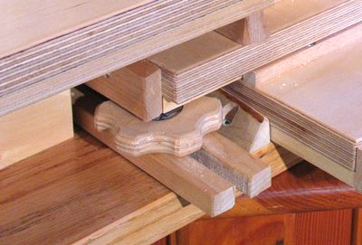
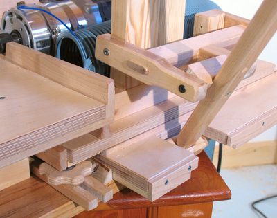 The drawer slides are ball bearing drawer slides, and are only half
an inch (13 mm) thick. I sandwiched them between pieces of 3/4" birch plywood.
The first layer of plywood just moves side to side on the base, while above that
the second layer can slide front to back using a second set of drawer
slides.
On the photo at left, you can see the first layer of plywood slid all the way to the right.
It has a large notch cut out of it to move around the base of the control lever.
The drawer slides are ball bearing drawer slides, and are only half
an inch (13 mm) thick. I sandwiched them between pieces of 3/4" birch plywood.
The first layer of plywood just moves side to side on the base, while above that
the second layer can slide front to back using a second set of drawer
slides.
On the photo at left, you can see the first layer of plywood slid all the way to the right.
It has a large notch cut out of it to move around the base of the control lever.
The control lever attaches to the router mounting assembly on the top layer of plywood. That way, the lever can be tilted side to side for the side motion, and front to back for the in/out motion of the router.
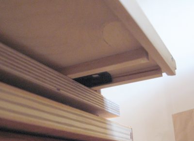 To protect the ball bearing slides from sawdust, I enclosed them as much as possible.
But with the carriage moved all the way to one side or the other,
you can barely see the ends of the slides from below - see the black thing in
the middle of the photo at left.
To protect the ball bearing slides from sawdust, I enclosed them as much as possible.
But with the carriage moved all the way to one side or the other,
you can barely see the ends of the slides from below - see the black thing in
the middle of the photo at left.
I'm hoping that I won't end up having to clean the sawdust out of them, because getting the whole assembly together was quite tricky and time consuming.
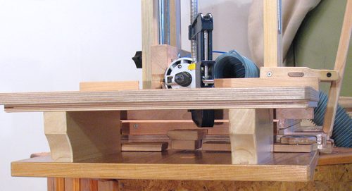 The carriage motion is restricted by adjustable stops for the left and right
motion, and another stop for the forward motion.
At left, you can see the left and right stops below the table. The block
just below the router is attached to the side to side piece of plywood,
and slides with the carriage. It can bump into blocks on either side of it, which
are tightened down with knobs.
The carriage motion is restricted by adjustable stops for the left and right
motion, and another stop for the forward motion.
At left, you can see the left and right stops below the table. The block
just below the router is attached to the side to side piece of plywood,
and slides with the carriage. It can bump into blocks on either side of it, which
are tightened down with knobs.
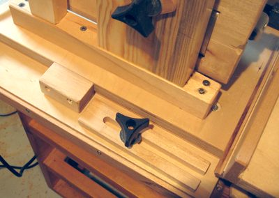
 Here you can see the knob for locking the right side stop. I had to make these knobs
fairly flat, because parts of the carriage can extend over the knob when slid
all the way forward and to the side. The knobs are just cut from a piece of
3/8" birch plywood, with a T-nut installed for the thread.
Here you can see the knob for locking the right side stop. I had to make these knobs
fairly flat, because parts of the carriage can extend over the knob when slid
all the way forward and to the side. The knobs are just cut from a piece of
3/8" birch plywood, with a T-nut installed for the thread.
 Another adjustable stop, on the left side of the machine, allows for controlling
the depth of the mortises.
Another adjustable stop, on the left side of the machine, allows for controlling
the depth of the mortises.
This is accomplished via a block screwed to the left side of the top most piece of plywood, which slides front to back. This block bumps against a stop which is fastened to the part of the sliding assembly that slides side to side.
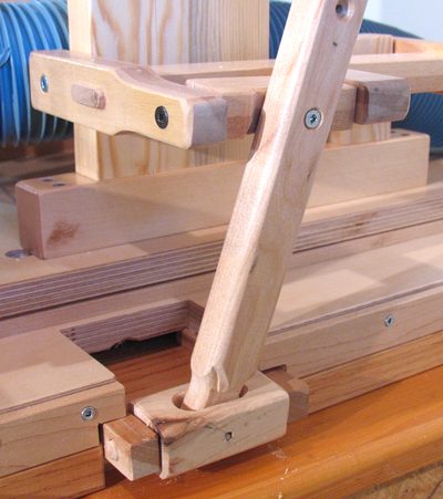 The whole sliding mechanism is controlled by just one lever. On commercial slot
mortising machines, this lever uses a ball and socket joint on the bottom and another
ball joint at the top. A ball joint would be rather hard to make out of wood.
So the way my lever is attached is something that works more like a universal joint.
Basically, side to side tilt is handled by a block that tilts side to side. The lever
is mounted in a slot in this block, which allows it to tilt front to back.
The whole sliding mechanism is controlled by just one lever. On commercial slot
mortising machines, this lever uses a ball and socket joint on the bottom and another
ball joint at the top. A ball joint would be rather hard to make out of wood.
So the way my lever is attached is something that works more like a universal joint.
Basically, side to side tilt is handled by a block that tilts side to side. The lever
is mounted in a slot in this block, which allows it to tilt front to back.
A similar arrangement is used for the upper mounting point, except that the shaft is only screwed to the side of this block. The bracket that this is attached to can tilt up and down, because the vertical bearing point on the lever does move up and down a little as the lever moves through its arc of motion.
I made both directions controlled with one lever instead of two partially because it would cut down on the number of levers I'd have to make, and also because I couldn't figure out a logical place for a second lever.
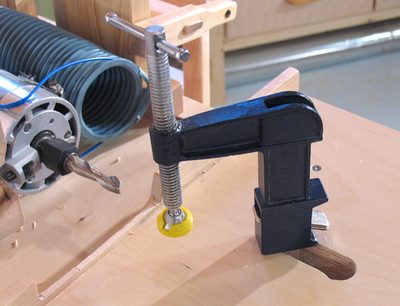 A clamp through the table is used to hold the work piece in place. The clamp
is a funny sort of cross between a bar clamp and a C clamp that I found at
Canadian Tire. It's well suited for this purpose, because it can be slid
closed around the hole in the table, so that the clamp stays in place even when not
tightened against a work piece.
A clamp through the table is used to hold the work piece in place. The clamp
is a funny sort of cross between a bar clamp and a C clamp that I found at
Canadian Tire. It's well suited for this purpose, because it can be slid
closed around the hole in the table, so that the clamp stays in place even when not
tightened against a work piece.
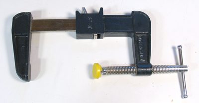 I had modified the clamp so that the two parts of it could
separate. I planned on just installing the clamp in a 1.25" hole in the table.
But it turned out to be impossible to insert the bottom half of the clamp with the
limited space under the table. So I had to expand the hole to a slot so that
the clamp could be inserted from above.
I had modified the clamp so that the two parts of it could
separate. I planned on just installing the clamp in a 1.25" hole in the table.
But it turned out to be impossible to insert the bottom half of the clamp with the
limited space under the table. So I had to expand the hole to a slot so that
the clamp could be inserted from above.