Building the screw advance box joint jig (v1)
(Continued from screw advance box joint jig (v1))
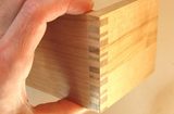
 The carriage of the jig consists just of a box of sorts, which is rabbet joined together
at the corners.
I suppose it would have been ideal to use this jig to make box joints for the corners,
but that's a bit of a chicken and egg problem.
So instead of using a box joint, I just rabbet joined the corners of the box. It needs to
be stiff more so than it needs to be ultimately strong. It should never see large forces.
The carriage of the jig consists just of a box of sorts, which is rabbet joined together
at the corners.
I suppose it would have been ideal to use this jig to make box joints for the corners,
but that's a bit of a chicken and egg problem.
So instead of using a box joint, I just rabbet joined the corners of the box. It needs to
be stiff more so than it needs to be ultimately strong. It should never see large forces.
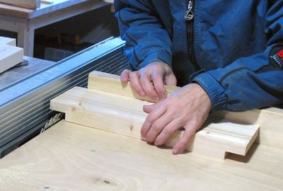
To flatten out the bottom of the rabbets, I moved the work piece side to side over a spinning blade. The flatness of the bottom of the rabbets is critical to ensure that the jig goes together square.
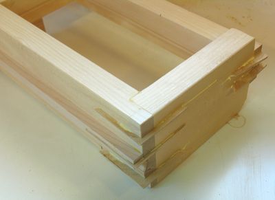 I added splines to the corners of the box. Basically, I cut a slot in at a 45 degree angle
with the table saw, and then glued a hardwood triangle into the slot. That makes for a
pretty sturdy joint.
I added splines to the corners of the box. Basically, I cut a slot in at a 45 degree angle
with the table saw, and then glued a hardwood triangle into the slot. That makes for a
pretty sturdy joint.
The carriage is not actually a whole box. Only two sides of it are the full height. The back and left sides of it don't serve as a reference surface, so I made them not extend as far up and down. This provides a bit more visibility, and makes it easier to put clamps on the work piece.
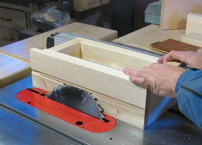 I cut the bevel for the half-dovetail into the box after I put the box together.
This might have been easier before putting it together, but I was kind of designing
the jig as I went along. I did make a rough CAD model of it initially but I usually
alter my plan a little
as I go along, and I wanted to get more of a sense of how things fit together before
cutting out that bevel. The saw blade is tilted towards the box by about 20 degrees in
the photo at left, and only the tip of the blade cuts into the wood.
I cut the bevel for the half-dovetail into the box after I put the box together.
This might have been easier before putting it together, but I was kind of designing
the jig as I went along. I did make a rough CAD model of it initially but I usually
alter my plan a little
as I go along, and I wanted to get more of a sense of how things fit together before
cutting out that bevel. The saw blade is tilted towards the box by about 20 degrees in
the photo at left, and only the tip of the blade cuts into the wood.
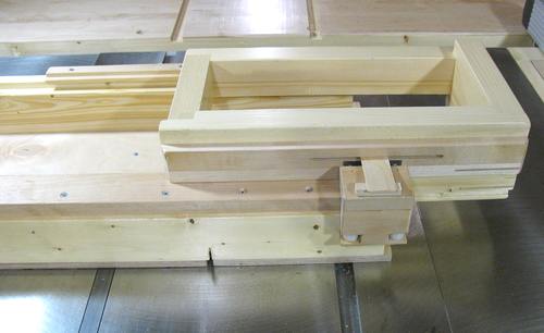
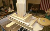
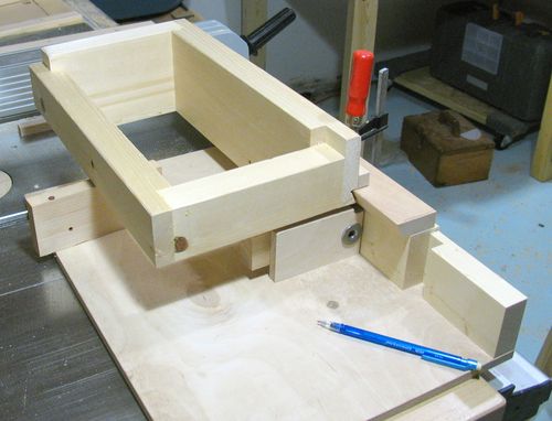 This photo shows the jig partially built, and me checking to see how things fit
together. Other than the carriage, nothing is permanently put together yet. The
base (sled) part is actually held together just by the clamp whose red handle you
can see near the center of the picture.
This photo shows the jig partially built, and me checking to see how things fit
together. Other than the carriage, nothing is permanently put together yet. The
base (sled) part is actually held together just by the clamp whose red handle you
can see near the center of the picture.
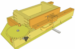
You can just see the end of a piece of hardwood that I glued just above the half dovetail, to vertically support the carriage. I later decided that this piece of hardwood should be a bit wider for mounting the pinch wheel assembly to it, so I glued another piece along side of it.
The vertical dado cut into part of the base, just above the blue pencil, will provide space for the secondary gear, which is mounted on the threaded rod.
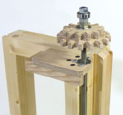 A 3/8" threaded rod is used to push the carriage. A t-nut attached to the carriage moves the
carriage side to side, while a ball bearing on the other end gives it a reference.
A 3/8" threaded rod is used to push the carriage. A t-nut attached to the carriage moves the
carriage side to side, while a ball bearing on the other end gives it a reference.
I also used a t-nut to mount the gears onto the shaft. Though, realistically, squishing the gears between two regular nuts would have done the job as well.
The ball bearing is one with a 3/8" hole and 1" on the outside diameter. It's a very common size of ball bearing. Although, if you use a 5/16" threaded rod instead of 3/8", you could even use the bearing from a pair of roller blades.
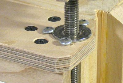 The t-nut that I used is the kind that has no prongs, and just twists into the hole.
It didn't hold quite well enough for my purposes, so I put some screws around it to hold
it in place.
The three black screws hold the piece of plywood that has the nut in it to
the carriage. I only screwed that piece of plywood on, so that I could replace the whole
piece of plywood and t-nut if I needed to. It was a bit tricky getting the
shaft to align perfectly with the carriage, and I had to put a little bit of shim under
parts of the t-nut's flange to get the alignment perfect.
The t-nut that I used is the kind that has no prongs, and just twists into the hole.
It didn't hold quite well enough for my purposes, so I put some screws around it to hold
it in place.
The three black screws hold the piece of plywood that has the nut in it to
the carriage. I only screwed that piece of plywood on, so that I could replace the whole
piece of plywood and t-nut if I needed to. It was a bit tricky getting the
shaft to align perfectly with the carriage, and I had to put a little bit of shim under
parts of the t-nut's flange to get the alignment perfect.
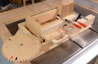
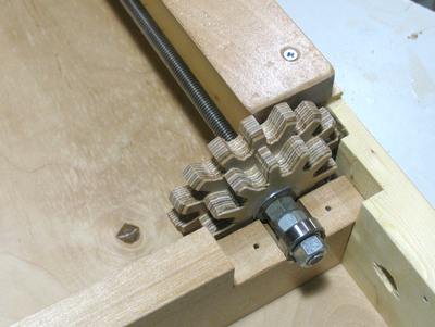 The photo at left shows how the gears mount in the jig.
There is not a lot of space around the gears. My original idea had been to just have one
size gear on the shaft, but later I decided it would be better to have two gears to allow
for more combinations. I enlarged the space for the gears just enough to allow for this.
The photo at left shows how the gears mount in the jig.
There is not a lot of space around the gears. My original idea had been to just have one
size gear on the shaft, but later I decided it would be better to have two gears to allow
for more combinations. I enlarged the space for the gears just enough to allow for this.
 The bearing has an outer diameter of 1". I drilled a 1" hole in a piece of wood, then
drilled the screw holes, and then cut the mounting block out. That way, I could be sure
my holes all lined up perfectly.
The bearing has an outer diameter of 1". I drilled a 1" hole in a piece of wood, then
drilled the screw holes, and then cut the mounting block out. That way, I could be sure
my holes all lined up perfectly.
Also note how the ball bearing is spaced away from the gears by two nuts. I found that the closer the carriage got to the ball bearing, the more critical alignment became. So I figured I'd keep the ball bearing a bit further to the left, so that it isn't overly close to the carriage's t-nut when the carriage is in its home position all the way to the left.
Another tricky aspect was that when I squeezed the bearing between the nuts, it would seem to always be not perfectly aligned with the threaded rod, so that if I twirled the rod in my hand, and held the bearing with my other hand, I could always feel it wobble. Wrapping one turn of electrical tape around the shaft made the bearing very tight to slip onto the shaft, and it aligned with the shaft much better.
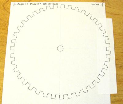 To make the gears, I used my gear template generator.
I used a tooth angle of 0 degrees and a tooth pitch of 17. The gear template generator makes
perfect involute spur gear shapes, but an "ideal" gear for this application would be a bevel gear,
which is a more complicated 3D shape. So I just set it to produce relatively square teeth, and
then cut them out a bit narrow, and filed them more round-ish on the side where it meshes with the
other gear. Basically, the idea was to give the gear teeth enough slack so that the non ideal
90 degrees meshing would still work, though definitely not as smoothly as nice involute
spur gears would.
To make the gears, I used my gear template generator.
I used a tooth angle of 0 degrees and a tooth pitch of 17. The gear template generator makes
perfect involute spur gear shapes, but an "ideal" gear for this application would be a bevel gear,
which is a more complicated 3D shape. So I just set it to produce relatively square teeth, and
then cut them out a bit narrow, and filed them more round-ish on the side where it meshes with the
other gear. Basically, the idea was to give the gear teeth enough slack so that the non ideal
90 degrees meshing would still work, though definitely not as smoothly as nice involute
spur gears would.
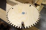
For the largest gears, such as a 39 tooth gear, the gear didn't entirely fit on one sheet of paper. So I printed two copies, and then cut out a section and glued it on the right side to complete the full circle of the gear.
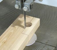
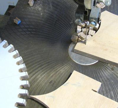 To speed up cutting of the gears, I drilled a 5/16" hole between the teeth, and then just made
two straight cuts in with the band saw. I clamped a piece of scrap plywood to the saw as shown,
so that in effect I had a zero clearance insert at the blade to prevent tearout on the
bottom side.
To speed up cutting of the gears, I drilled a 5/16" hole between the teeth, and then just made
two straight cuts in with the band saw. I clamped a piece of scrap plywood to the saw as shown,
so that in effect I had a zero clearance insert at the blade to prevent tearout on the
bottom side.
I used another scrap in front of this to help keep the gear level.
Even if you have a CNC router to cut the gears for you (which I don't), I recommend just cutting the gears on the band saw. From what I have heard, a CNC router is much slower than cutting it by hand, because the feed rate is quite slow, and it usually takes multiple passes to cut to full depth.
Pinch wheel assembly
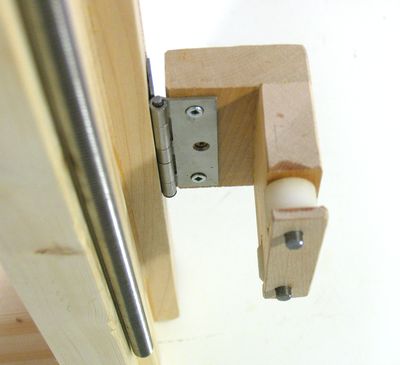 To keep the carriage positioned on the base sled consistently, I wanted it to always be pushed
against the half dovetail. So I made a "pinch wheel assembly". The pinch wheel
assembly essentially pulls the carriage against the half dovetail. I used two nylon rollers
that I had kicking around my junk drawers. Ball bearings (same ones as used on the shaft) would
be slightly better.
To keep the carriage positioned on the base sled consistently, I wanted it to always be pushed
against the half dovetail. So I made a "pinch wheel assembly". The pinch wheel
assembly essentially pulls the carriage against the half dovetail. I used two nylon rollers
that I had kicking around my junk drawers. Ball bearings (same ones as used on the shaft) would
be slightly better.
 The pinch wheel assembly is sprung by just a thin piece of wood with a spacer under it.
The thin piece of wood goes into a slot in the carriage, that I'd cut by
putting the carriage onto my table saw, and raising a thin dado stack into it.
The pinch wheel assembly is sprung by just a thin piece of wood with a spacer under it.
The thin piece of wood goes into a slot in the carriage, that I'd cut by
putting the carriage onto my table saw, and raising a thin dado stack into it.
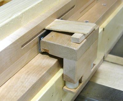
 When cutting stock that is 30 cm wide, the carriage extends all the way to the right
for the last cut.
In this position, one of the pinch rollers actually goes off the end of the rail
but the second one is still ok. This is a bit of an extreme case anyway.
When cutting stock that is 30 cm wide, the carriage extends all the way to the right
for the last cut.
In this position, one of the pinch rollers actually goes off the end of the rail
but the second one is still ok. This is a bit of an extreme case anyway.
I could have made the base sled a little bit wider, but the jig was already kind of bulky, and I figured I would not be cutting box joints that wide that often.
There is also the risk that for deeply cut box or finger joints, that the saw blade will cut into the pinch roller assembly. Realistically, the sled doesn't need to be pushed that far for the center of the blade to cut through the stock, but it could happen. It's something to watch out for.
One thing that I don't have to worry about is cutting into the threaded rod, seeing that the threaded rod doesn't move laterally. In fact, the threaded rod ends about 2 cm before the blade, regardless of the carriage position.
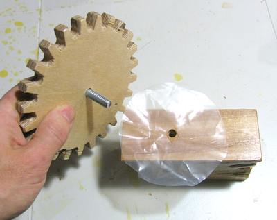 Each primary gear is attached to its own wood block. I used a relatively slippery varnish to
varnish the gear and the block, and then also cut a disk from some relatively thick polyethylene
foil to go as a washer between. That really cuts down on friction.
Each primary gear is attached to its own wood block. I used a relatively slippery varnish to
varnish the gear and the block, and then also cut a disk from some relatively thick polyethylene
foil to go as a washer between. That really cuts down on friction.
The bolt that the gear turns on isn't threaded all the way. It's smooth for the part that goes through the gear. I also put a drop of oil on the inside of that hole to make it turn more easily.
I have drawn up some free plans for this version of the jig.
I also built an imrpoved version 2 of the jig.
Many more photos and detailed instructions on how to
build it are included in the
plans for sale
Back to screw advance box joint jig version 1
See also:
 Cutting box joints without a dado blade |
 Screw advance box joint jig version 2 |
 Plans for the box joint jig (v2) |
 Differnt styles of box joints |
 Jim Lundin's box joint jig |
More about box joints and jigs