Building the wooden combination lock
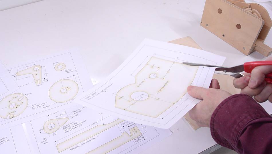 I started by printing out the 1:1 templates from the plans,
here cutting out the template for the front panel.
I started by printing out the 1:1 templates from the plans,
here cutting out the template for the front panel.
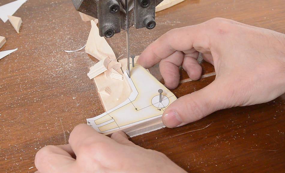
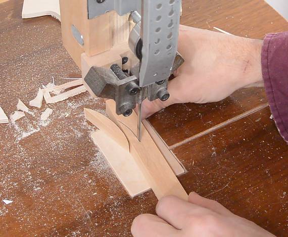
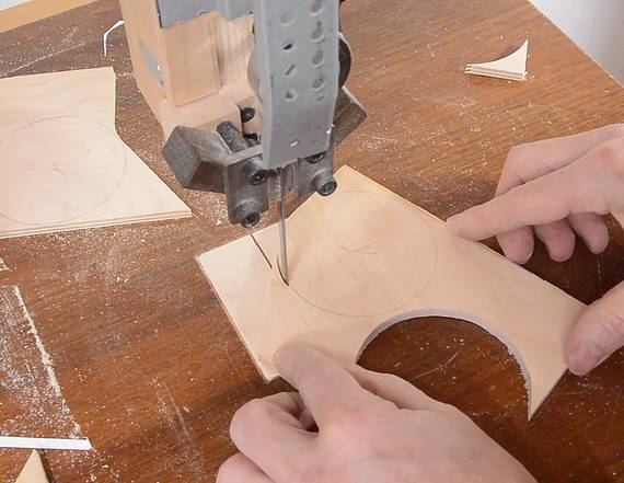
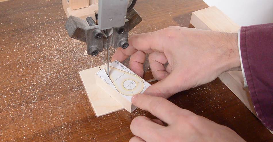
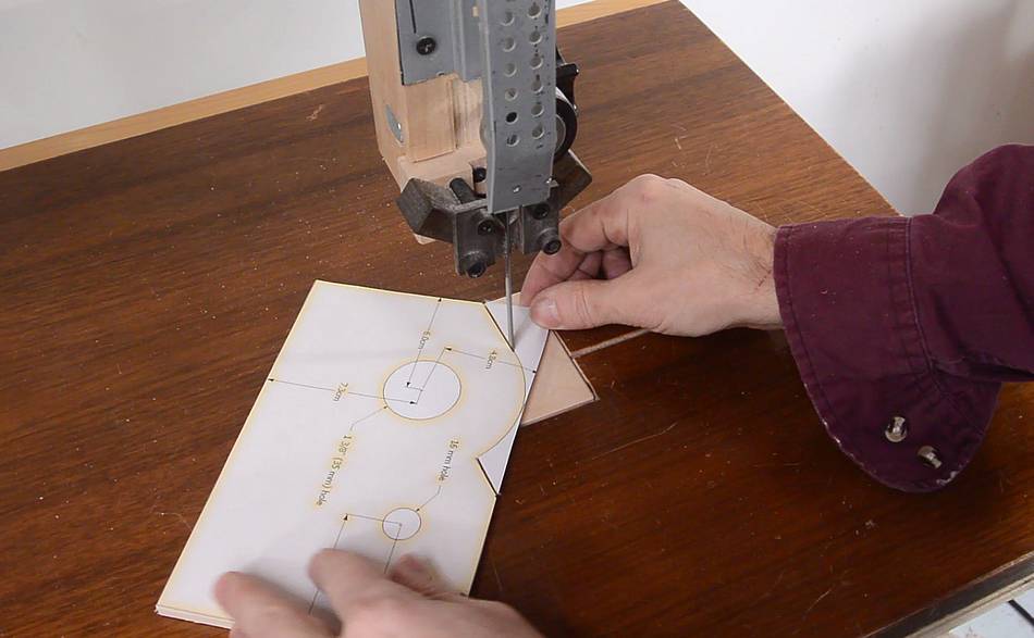 I glued the front-frace template onto a rectangular piece of 1/4" (6 mm) plywood
with glue stick to cut out the front face's profile.
I glued the front-frace template onto a rectangular piece of 1/4" (6 mm) plywood
with glue stick to cut out the front face's profile.
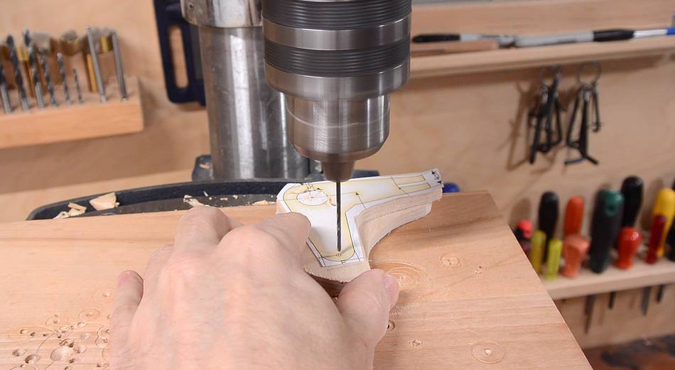
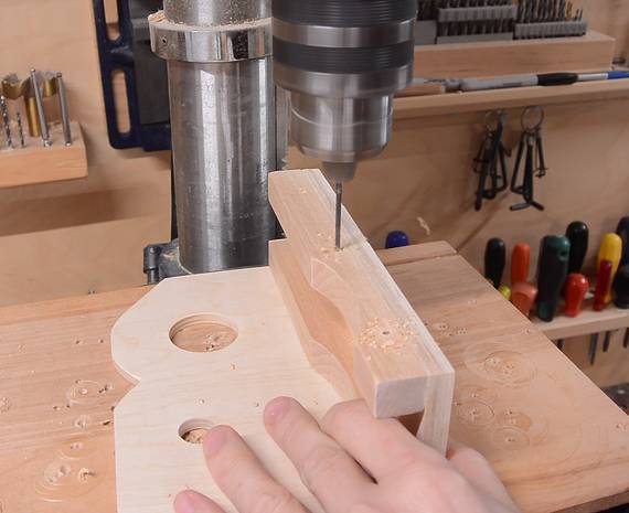
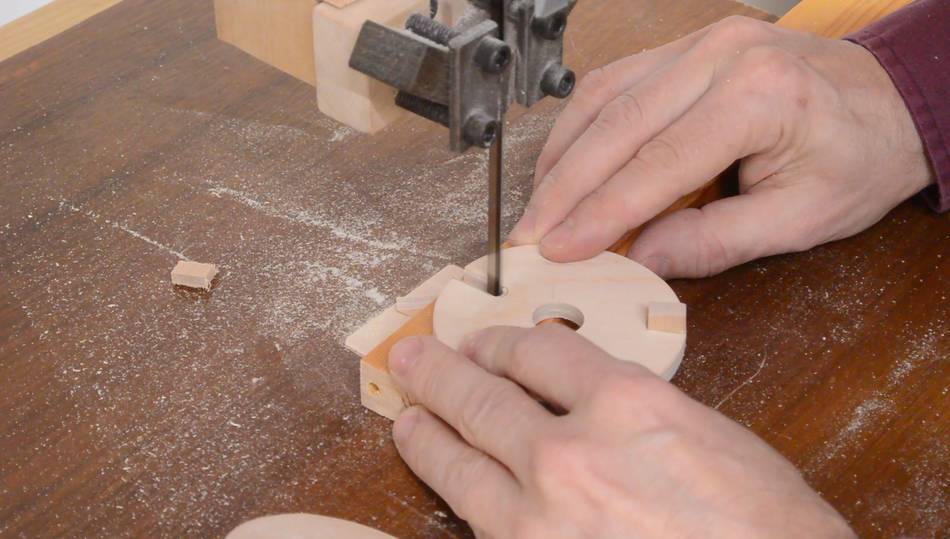
Before that, I had also laid this template onto the back piece and punched the hole centers through with an awl. The back only has a few holes, so I didn't bother to print that template. The holes are in the same place front and back.
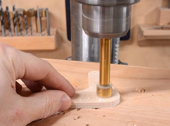
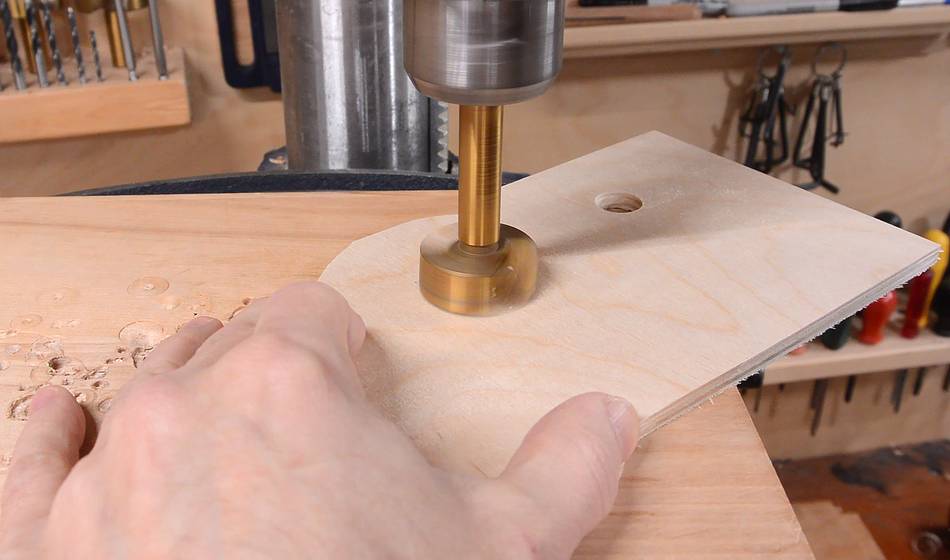 I punched divots through the centers of the holes, then peeled off the front template
and drilled the holes with Forstner bits. This way, I don't get the drill
chewing up the template. The divots naturally guide the point of the
Forstner bit to the exact location.
I punched divots through the centers of the holes, then peeled off the front template
and drilled the holes with Forstner bits. This way, I don't get the drill
chewing up the template. The divots naturally guide the point of the
Forstner bit to the exact location.
 The L-bracket part needs two identical pieces, so I stuck two pieces of plywood
together with glue stick, then drilled pilot holes for the two holes in both pieces.
The L-bracket part needs two identical pieces, so I stuck two pieces of plywood
together with glue stick, then drilled pilot holes for the two holes in both pieces.
 I then cut the pieces on the bandsaw. The glue stick didn't stick well enough,
so I put two small nails into the pilot holes to keep the pieces aligned as
I cut.
I then cut the pieces on the bandsaw. The glue stick didn't stick well enough,
so I put two small nails into the pilot holes to keep the pieces aligned as
I cut.
After that, I drilled the correct size holes using the pilot holes as a guide.
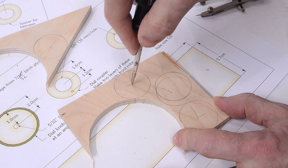
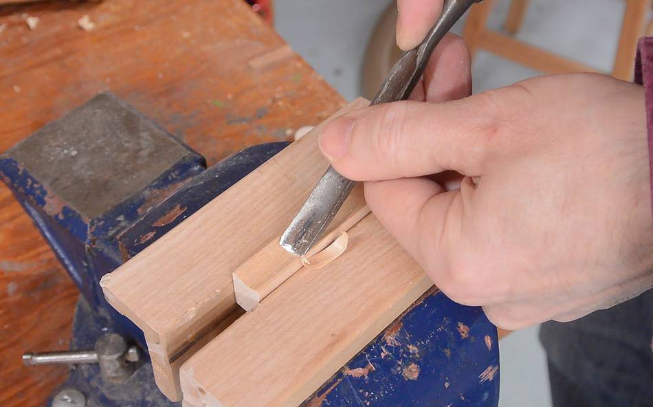 A spacer needs to go between the two L-shaped pieces of plywood. This spacer
goes against the 5/8" (16 mm) dowel, so it needs a round curve cut out
of it to match the dowel's radius. I carved that out using a gouge (a
curved chisel)
A spacer needs to go between the two L-shaped pieces of plywood. This spacer
goes against the 5/8" (16 mm) dowel, so it needs a round curve cut out
of it to match the dowel's radius. I carved that out using a gouge (a
curved chisel)
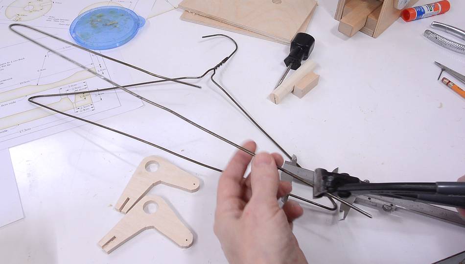 A metal pin goes between the two L-bracket. I cut this from some coat hangers.
 And a thin wooden strip also goes between them. I cut this from some solid
hardwood. It's only a few millimeters thick, but by not cutting all the way
to the end, the thin piece doesn't end up flying into the saw or getting kicked
back. After that, I cut off the length that I needed.
And a thin wooden strip also goes between them. I cut this from some solid
hardwood. It's only a few millimeters thick, but by not cutting all the way
to the end, the thin piece doesn't end up flying into the saw or getting kicked
back. After that, I cut off the length that I needed.
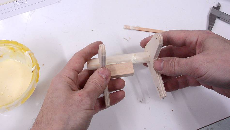
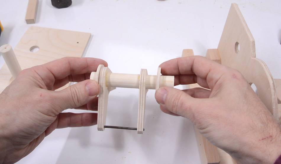
 Assembling the L-bracket on a piece of dowel, with the spacer I
made earlier. The piece of coat hanger wire goes between the small holes,
and the thin strip of wood fits into the slots.
Assembling the L-bracket on a piece of dowel, with the spacer I
made earlier. The piece of coat hanger wire goes between the small holes,
and the thin strip of wood fits into the slots.
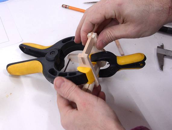
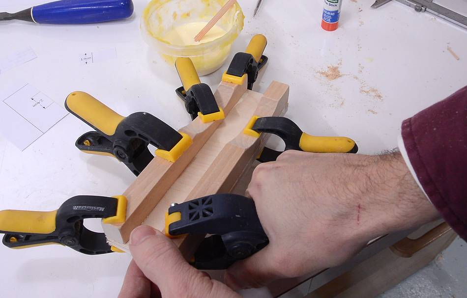
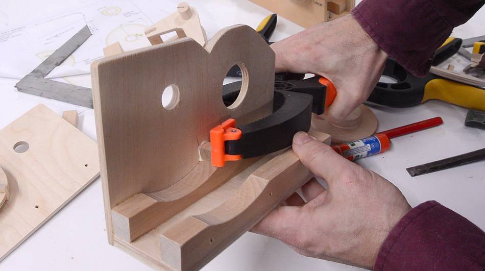
After that, I put some clamps on it and let the glue dry.
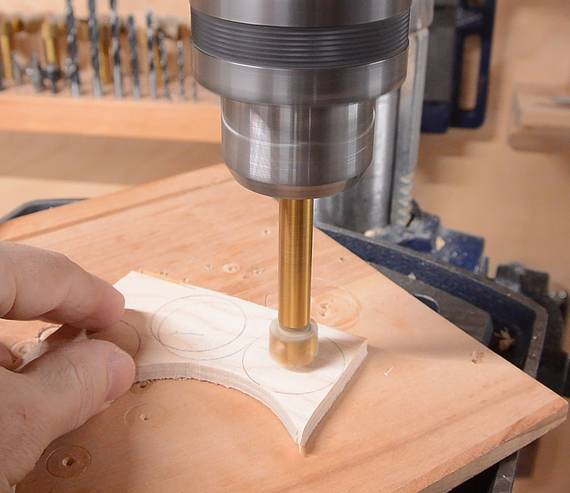
 Two strips of wood that go on the bottom have an arc cut out to clear the
L-bracket as it rotates. I cut out the template, laid it on the wood
(without gluing) and traced the curve with a pencil. It wasn't worth
gluing the template on.
Two strips of wood that go on the bottom have an arc cut out to clear the
L-bracket as it rotates. I cut out the template, laid it on the wood
(without gluing) and traced the curve with a pencil. It wasn't worth
gluing the template on.
 These two pieces are glued onto the bottom of the lock. The space between
them should be about half a millimeter wider than the "bolt" part.
These two pieces are glued onto the bottom of the lock. The space between
them should be about half a millimeter wider than the "bolt" part.
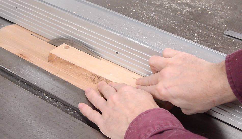
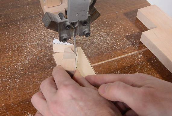
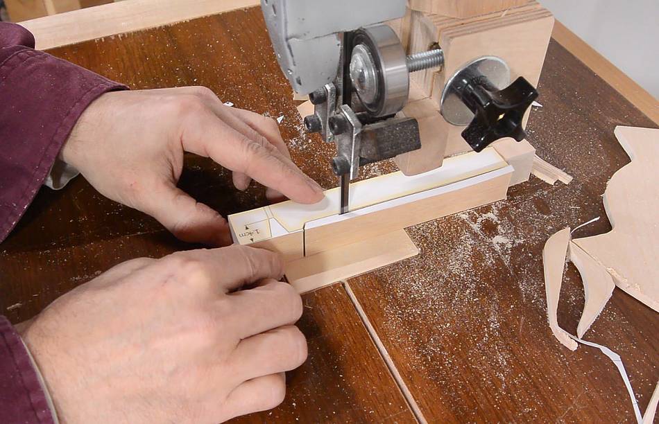 Cutting out the "bolt".
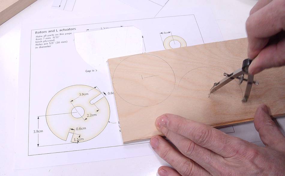
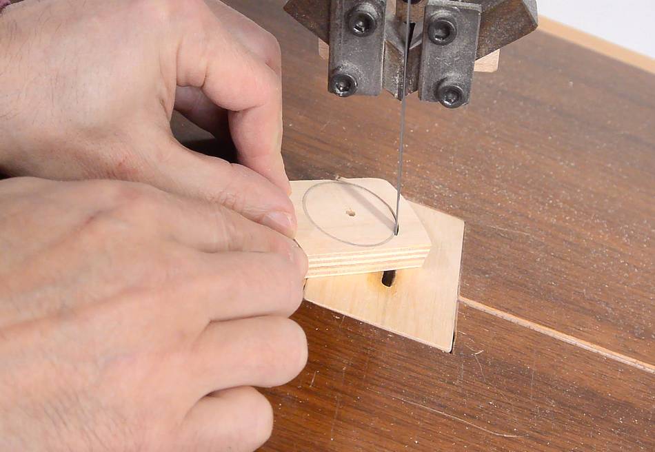
 The three rotors and the front dial are all circles of the same diameter.
I figured it was more convenient to just use a compass to draw the circles
on some plywood than to paste on the templates. Then I cut them out with
a bandsaw.
The three rotors and the front dial are all circles of the same diameter.
I figured it was more convenient to just use a compass to draw the circles
on some plywood than to paste on the templates. Then I cut them out with
a bandsaw.
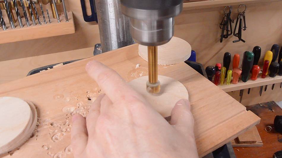 Then drilling the holes. Before drilling, I used an awl to enlarge
the compass center hole so that the drill's point can find the hole.
Then drilling the holes. Before drilling, I used an awl to enlarge
the compass center hole so that the drill's point can find the hole.
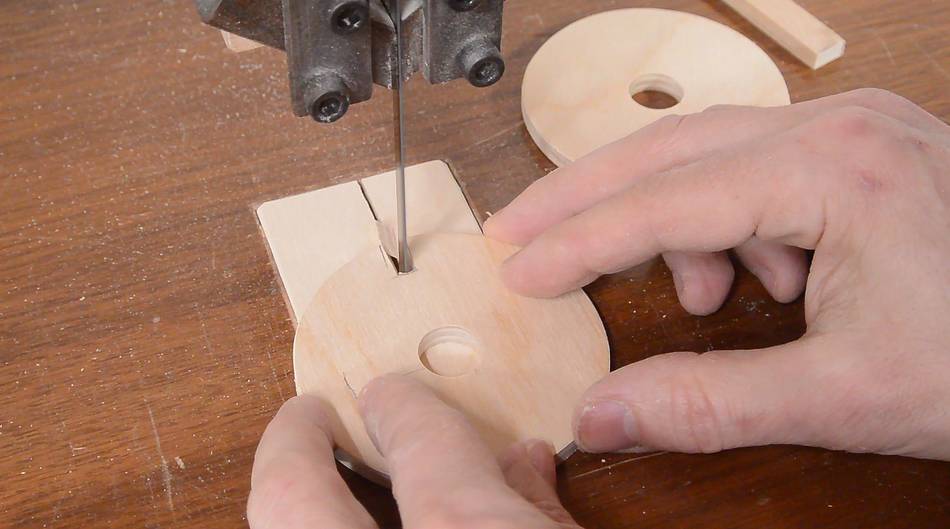
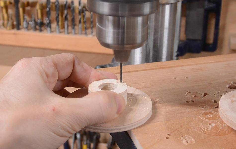
 I also needed a whole bunch of smaller disks as spacers. After drawing
the circles, I used an awl to enlarge the center divots,
then drilled out the 5/8" (16 mm) holes before cutting the circles out.
I also needed a whole bunch of smaller disks as spacers. After drawing
the circles, I used an awl to enlarge the center divots,
then drilled out the 5/8" (16 mm) holes before cutting the circles out.
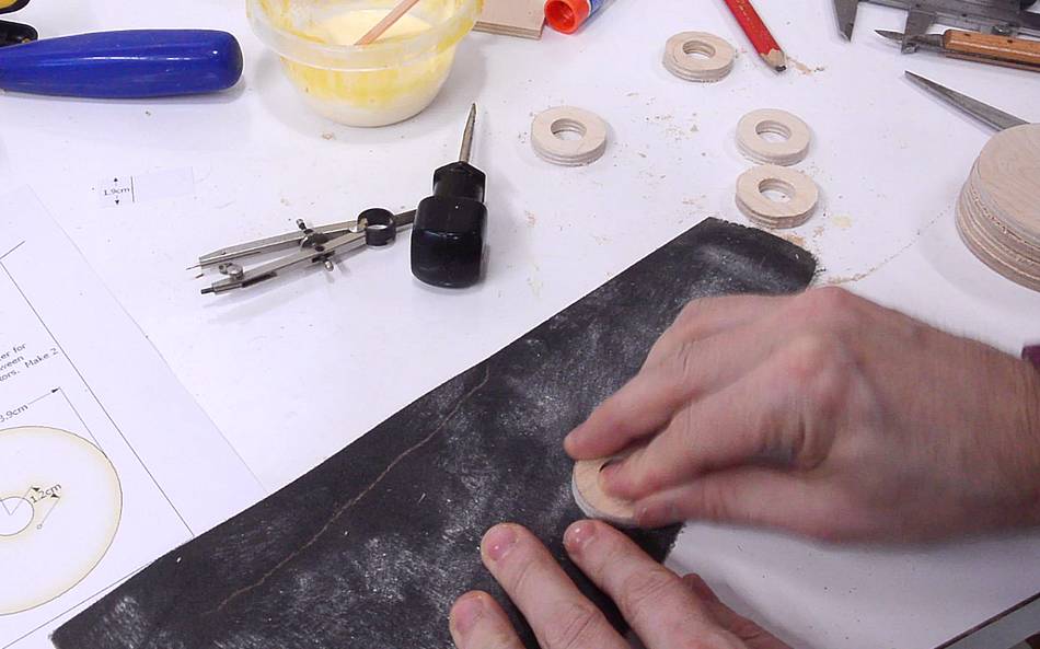 Some of the circles have some chip-out and burrs at the bottom. I used
some sandpaper to clean that up.
Some of the circles have some chip-out and burrs at the bottom. I used
some sandpaper to clean that up.
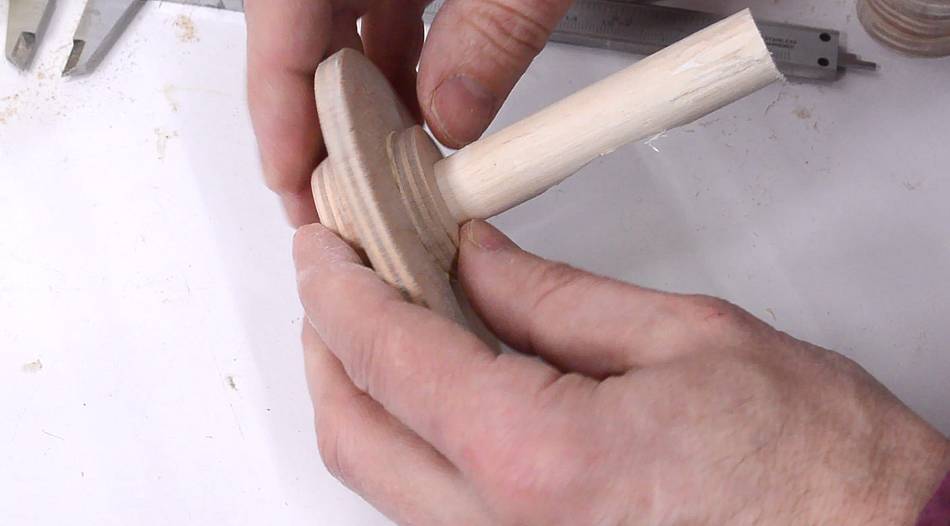
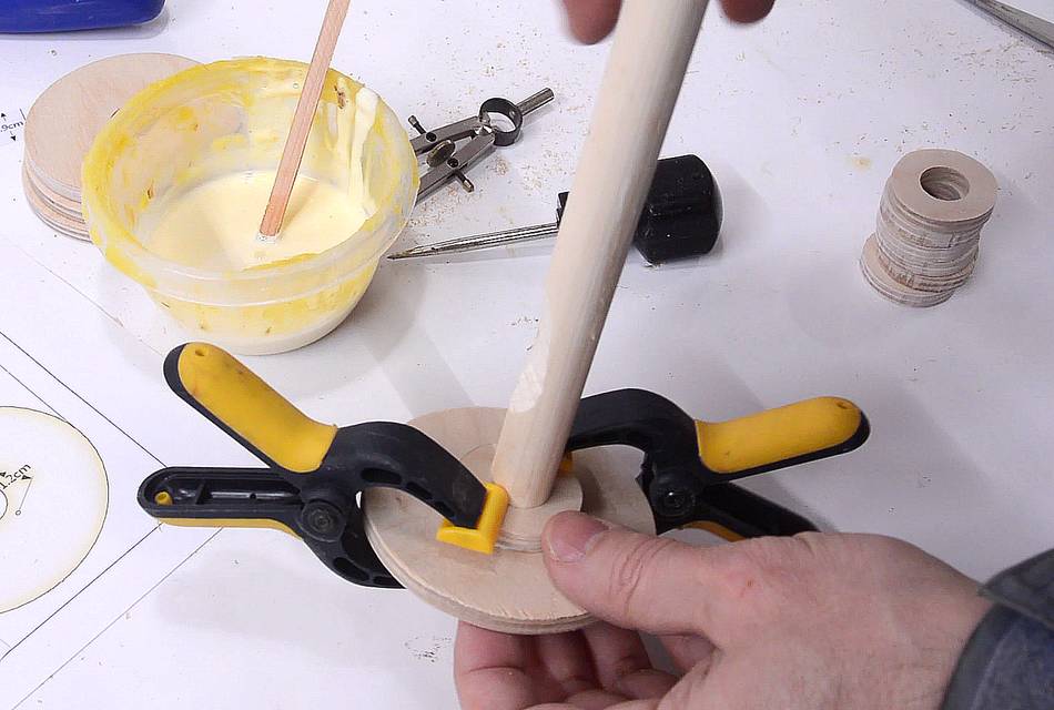 One of the small circles is glued on the back of the dial. I used a piece
of dowel to help line up the holes, then applied clamps. Then, before the glue
fully dried, I pulled out the dowel to make sure it doesn't get glued in
place.
One of the small circles is glued on the back of the dial. I used a piece
of dowel to help line up the holes, then applied clamps. Then, before the glue
fully dried, I pulled out the dowel to make sure it doesn't get glued in
place.
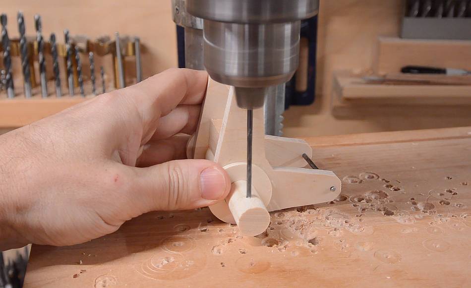
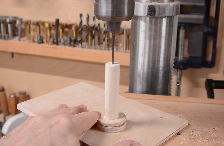
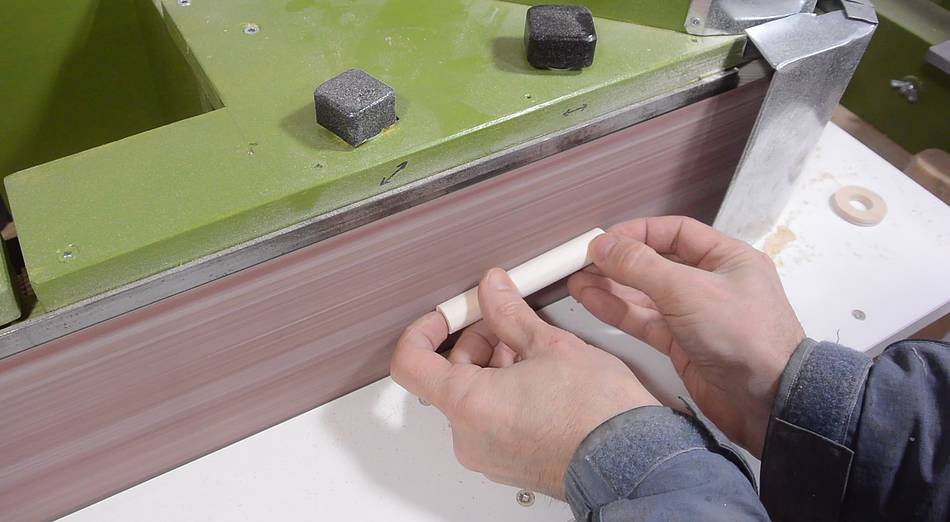 The rotors all need to turn freely on a dowel. My dowels fit very tightly
in the 5/8" holes, so I used my belt sander
to sand the dowel down a bit to make a looser fit.
The rotors all need to turn freely on a dowel. My dowels fit very tightly
in the 5/8" holes, so I used my belt sander
to sand the dowel down a bit to make a looser fit.
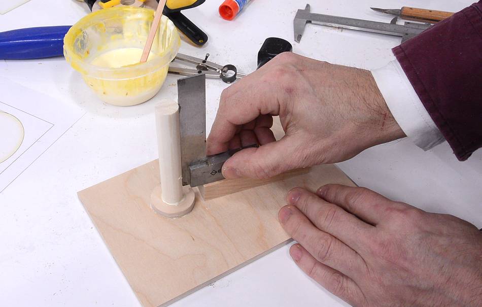 This piece of dowel gets glued into the back panel, with one of the rings to help
reinforce this connection. It's important that this dowel is square in the
panel. I ended up placing two squares next to it to hold it square
while the glue dried.
This piece of dowel gets glued into the back panel, with one of the rings to help
reinforce this connection. It's important that this dowel is square in the
panel. I ended up placing two squares next to it to hold it square
while the glue dried.
 The knob for the dial has a bevel on the sides. I tilted the bandsaw by about 20 degrees
before cutting this piece out.
The knob for the dial has a bevel on the sides. I tilted the bandsaw by about 20 degrees
before cutting this piece out.
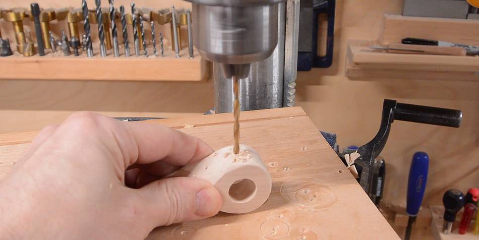
 There is also a hole about 3/4 of the way through this knob. I lined this up by first
drilling a pilot hole from the front, then using that pilot hole to drill the hole
from the back.
There is also a hole about 3/4 of the way through this knob. I lined this up by first
drilling a pilot hole from the front, then using that pilot hole to drill the hole
from the back.
I lined it up with the dial and disk on the back, again with a dowel in the hole, then applied clamps,then removed the dowel before the glue fully set.
 The rotors all have a notch cut out of them for the tabs that allow one rotor
to engage with the next rotor.
The rotors all have a notch cut out of them for the tabs that allow one rotor
to engage with the next rotor.
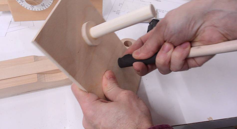
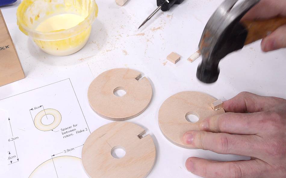 The tabs fit rather tightly, so I used a hammer to tap them in.
The front and back rotors have a tab that sticks out on one side, while the middle rotor has a longer tab that sticks out both sides.
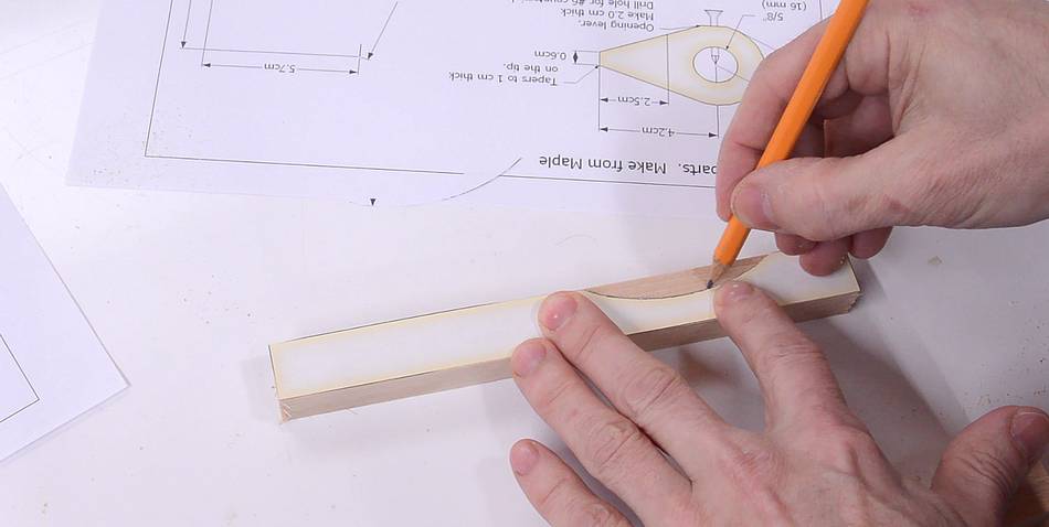
 Cutting out the open lever. I cut the sides of the point, but
didn't cut them all the way off. I then flipped it on its side and cut the
pointer end to be less thick, I then flipped it back again and finished
cutting out the shape.
Cutting out the open lever. I cut the sides of the point, but
didn't cut them all the way off. I then flipped it on its side and cut the
pointer end to be less thick, I then flipped it back again and finished
cutting out the shape.
 Drilling a hole for a screw to attach it to the dowel. I also added a
countersink for the screw head.
Drilling a hole for a screw to attach it to the dowel. I also added a
countersink for the screw head.
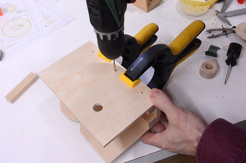
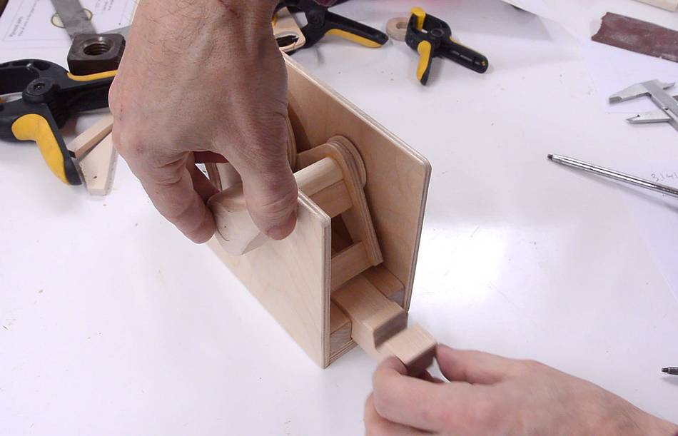
 When attaching the back, it's important that the dowel attached to the
back ends up centered in the large hole on the front.
I lined it up and held it in place with some spring clamps, then used
a drill to mark a small divot for where the holes line up.
When attaching the back, it's important that the dowel attached to the
back ends up centered in the large hole on the front.
I lined it up and held it in place with some spring clamps, then used
a drill to mark a small divot for where the holes line up.
I then used those divots to line up the pilot hole locations, which I drilled on the drill press.
 A small "stop" attaches to the back of the front panel. This keeps the
L-bracket from rotating past the "closed" position.
A small "stop" attaches to the back of the front panel. This keeps the
L-bracket from rotating past the "closed" position.
 I messed up when I glued together the L-bracket. I should have positioned the
dowel further towards the front (for the knob). Rather than make it again,
I just glued another short piece of dowel onto the end of the one that's there.
End grain to end grain joints, if done with enough glue, can be surprisingly strong.
I messed up when I glued together the L-bracket. I should have positioned the
dowel further towards the front (for the knob). Rather than make it again,
I just glued another short piece of dowel onto the end of the one that's there.
End grain to end grain joints, if done with enough glue, can be surprisingly strong.
If you build one, I'd recommend using a longer dowel when gluing up this bracket, that way you don't have to worry about positioning it just right. After it's glued up, cut the dowel to the right length.
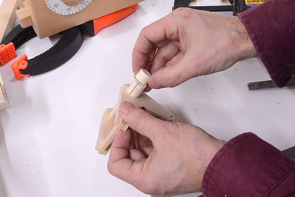
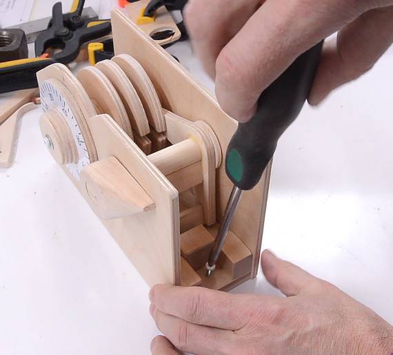
 Drilling the hole for the screw that attaches the knob.
 The dowel that the L-bracket rotates on fits very tightly in the holes I drilled
in the front and back panel. So I wrapped some sand paper around a 1/2" dowel
and used that to sand the holes larger until the dowel could rotate freely.
The dowel that the L-bracket rotates on fits very tightly in the holes I drilled
in the front and back panel. So I wrapped some sand paper around a 1/2" dowel
and used that to sand the holes larger until the dowel could rotate freely.
 The front dial needs to couple its rotation to the first rotor. But the knob
needs to be in front of the front panel, and the rotor behind it, so I didn't
want to glue them together.
The front dial needs to couple its rotation to the first rotor. But the knob
needs to be in front of the front panel, and the rotor behind it, so I didn't
want to glue them together.
A pin through both pieces transfers rotation. Here drilling the hole in the front rotor part.
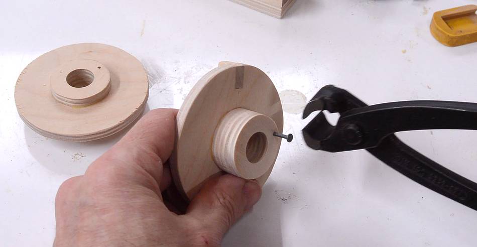 The "pin" is just a nail with the head cut off.
 I had to make an odd thickness "washer" to go behind the rotors to get them
positioned just right. I made this by sanding down one of the washers I made
earlier on the belt sander.
I had to make an odd thickness "washer" to go behind the rotors to get them
positioned just right. I made this by sanding down one of the washers I made
earlier on the belt sander.
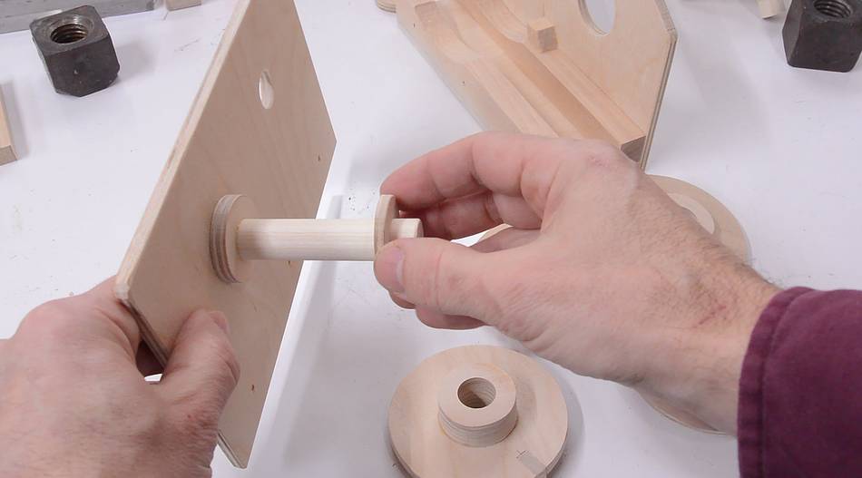
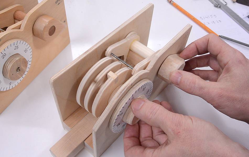
 Here's how the front knob fits on. Note that in this photo, the front rotor
is pushed way forward. The back of the knob actually protrudes through the
front panel (whereas this shows the front rotor part protruding through).
Here's how the front knob fits on. Note that in this photo, the front rotor
is pushed way forward. The back of the knob actually protrudes through the
front panel (whereas this shows the front rotor part protruding through).
 I also had to make two thinner washers to go on either side of the L-shaped bracket
to center it in the lock. You can make these out of 1/8" (3 mm) plywood,
or use 1/4" plywood and then sand them down to the right thickness.
I also had to make two thinner washers to go on either side of the L-shaped bracket
to center it in the lock. You can make these out of 1/8" (3 mm) plywood,
or use 1/4" plywood and then sand them down to the right thickness.
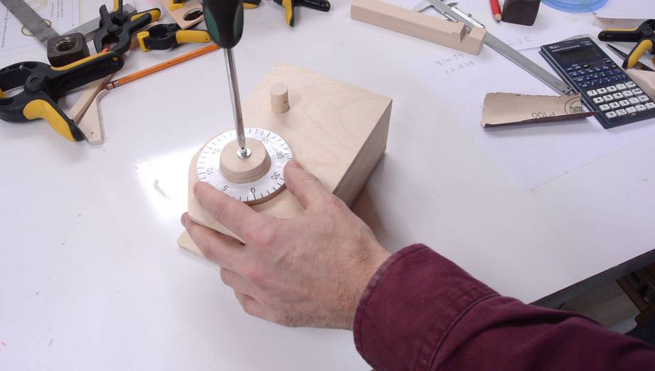
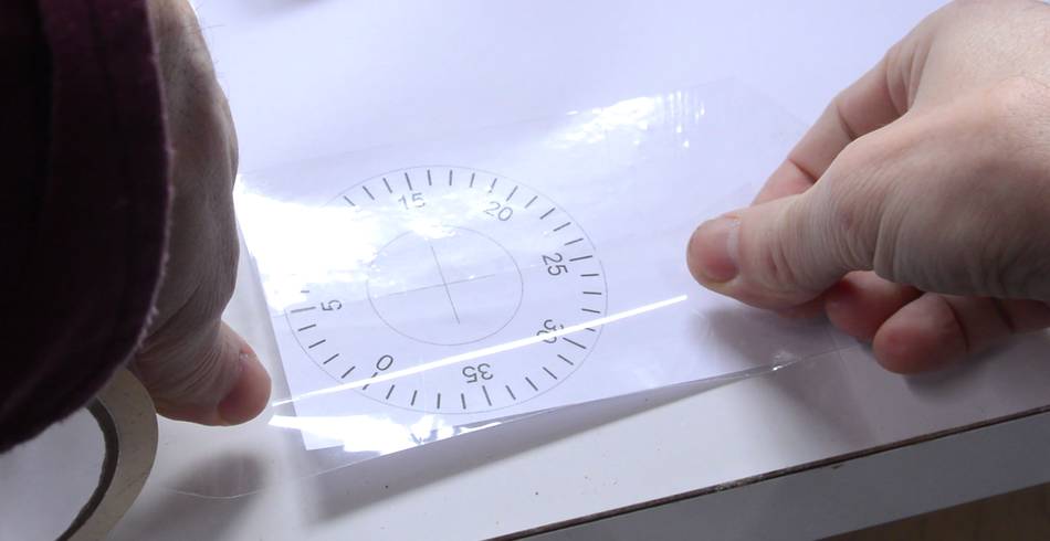 I printed out the dial for the lock and put some packing tape on the front
of it to protect it. I then glued it to the front dial using wood glue.
I printed out the dial for the lock and put some packing tape on the front
of it to protect it. I then glued it to the front dial using wood glue.
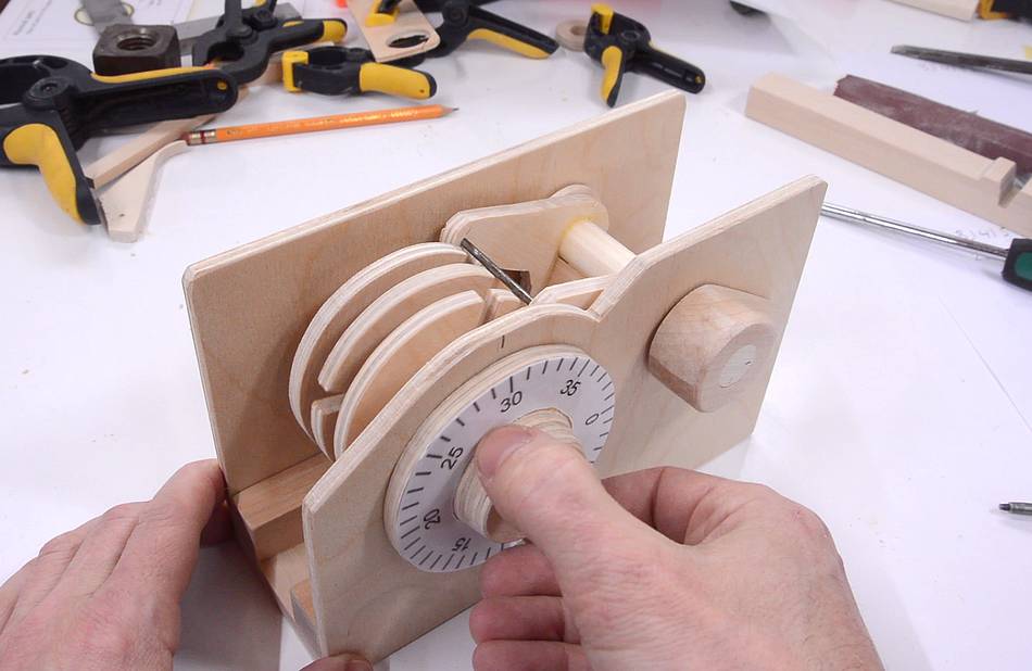
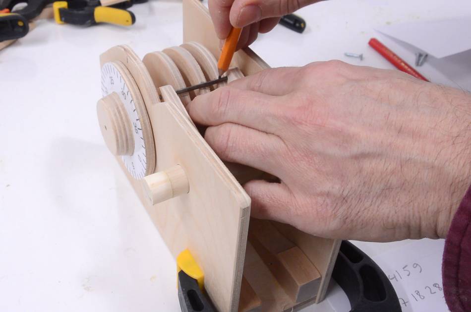 I then assembled the lock temporarily. The dials still don't have notches in
them. To figure out where to put the notches, I simply dialled in the combination
and then marked where the notches line up with the coat hanger wire.
I based the combination on
the mathematical constant e, which is 2.7182818284...
so the numbers are 27, 18, 28. I first wanted to use Pi(π), but
the dial only goes up to 39, so 31,41,59 would not have worked.
I then assembled the lock temporarily. The dials still don't have notches in
them. To figure out where to put the notches, I simply dialled in the combination
and then marked where the notches line up with the coat hanger wire.
I based the combination on
the mathematical constant e, which is 2.7182818284...
so the numbers are 27, 18, 28. I first wanted to use Pi(π), but
the dial only goes up to 39, so 31,41,59 would not have worked.
 I then took the rotors out and cut the notches on the bandsaw.
 The fixed shaft that the rotors sit on needs a hole in the front for a small screw
that holds the knob on.
The fixed shaft that the rotors sit on needs a hole in the front for a small screw
that holds the knob on.
 Screwing on the knob. The hole in the front of the knob needs to be large enough
to provide clearance around the screw (which doesn't rotate with the knob).
Screwing on the knob. The hole in the front of the knob needs to be large enough
to provide clearance around the screw (which doesn't rotate with the knob).
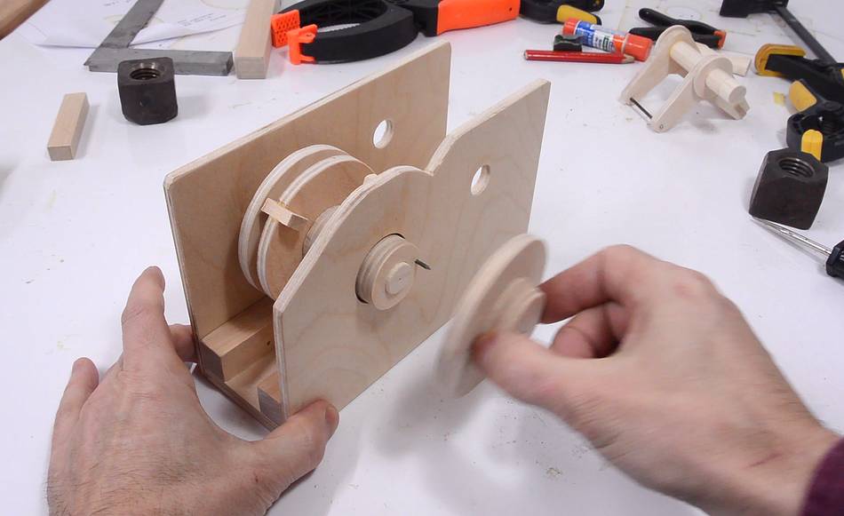
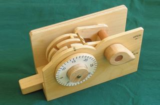
 Lock almost done.
 The bolt is best inserted by "opening" the lock, turning the lever past "open", and
inserting the bolt from the right side.
The bolt is best inserted by "opening" the lock, turning the lever past "open", and
inserting the bolt from the right side.
A screw behind the bolt then prevents the bolt from sliding out the right side.
 Ideally, the rotors would turn on the shaft with some friction. But if I made them slightly
tight on the dowel, as soon as the humidity levels change, they could become too loose
or too tight.
Ideally, the rotors would turn on the shaft with some friction. But if I made them slightly
tight on the dowel, as soon as the humidity levels change, they could become too loose
or too tight.
As it is, I have to dial the combination slowly. If I dial too fast, the rotors will overshoot their position from momentum.
But the whole lock is really not that practical. It's more there to demonstrate how a combination lock works.
See also:
 Wooden combination lock
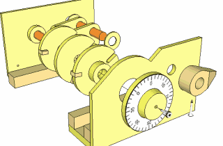 Buy plans for the lock
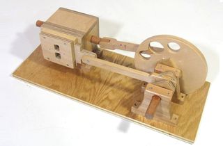 wooden air engine
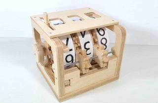 Mechanical counter
Back to my Woodworking website