Making the elevating gears
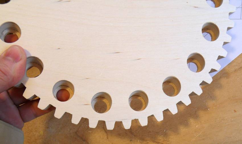
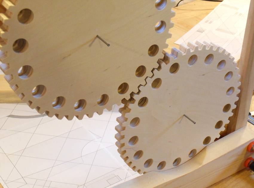 This marble machine uses two wheels with holes for elevating
the marbles. The holes are inclined at a slight angle so that marbles roll
into the holes at the bottom, and out of the holes when they reach the top.
(more on elevating wheels)
The wheels have gear teeth around the perimeter to drive them.
This marble machine uses two wheels with holes for elevating
the marbles. The holes are inclined at a slight angle so that marbles roll
into the holes at the bottom, and out of the holes when they reach the top.
(more on elevating wheels)
The wheels have gear teeth around the perimeter to drive them.
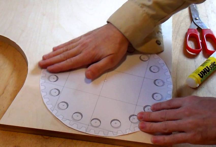 The shape for the gears comes from paper templates. I used glue stick to glue the template on.
It's only necessary to put glue around the edges where
cutting is done, plus a dab in the middle, just to make sure the center mark stays in place.
The shape for the gears comes from paper templates. I used glue stick to glue the template on.
It's only necessary to put glue around the edges where
cutting is done, plus a dab in the middle, just to make sure the center mark stays in place.
The glue stick has the advantage that it isn't a very strong glue and doesn't soak into the wood, so it's easier to get off afterwards. It also doesn't expand the paper as much as some glues. I apply the glue to the paper, then stick the paper down. For most liquid glues, it's better to apply the glue to the wood so that the paper won't distort before you glue it down.
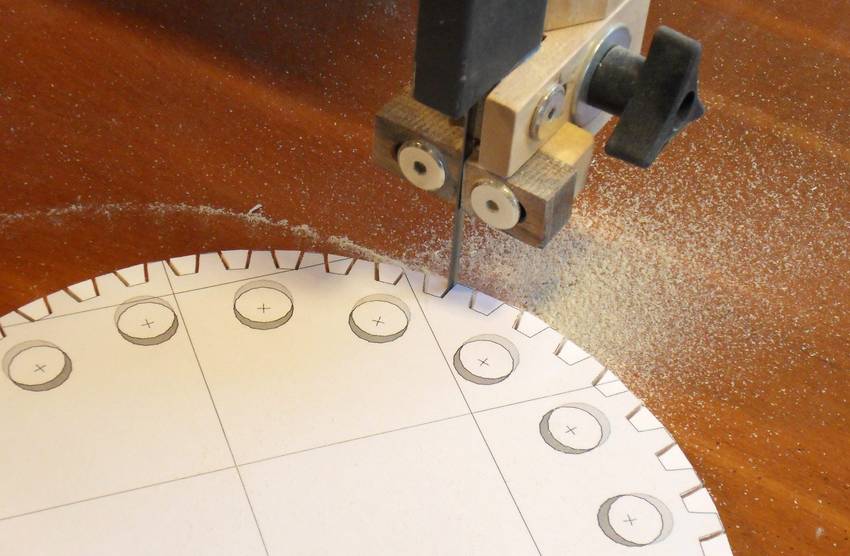 I start by cutting the sides of every tooth. The cut is made on the waste side of the line,
just barely cutting away the line itself.
I start by cutting the sides of every tooth. The cut is made on the waste side of the line,
just barely cutting away the line itself.
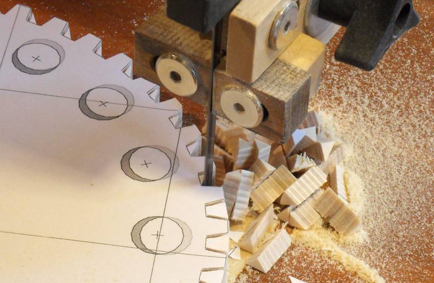 Next I make a diagonal cut in every tooth space. This cuts away most of the
waste between the teeth.
Next I make a diagonal cut in every tooth space. This cuts away most of the
waste between the teeth.
My usual procedure for making gears involves drilling a hole in every tooth space to remove most of the waste, but with the holes for the marbles so close to the edge, I didn't want to make the cutout any deeper than necessary.
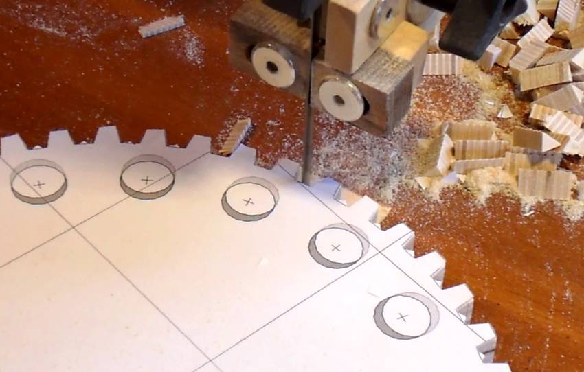 After the first diagonal cut, I make another diagonal cut in the opposite direction.
That leaves just a small triangle of material between the teeth. I remove this by
making a series of side-by-side cuts to hog it out. Having enough tension
on the bandsaw blade helps to stabilize it.
After the first diagonal cut, I make another diagonal cut in the opposite direction.
That leaves just a small triangle of material between the teeth. I remove this by
making a series of side-by-side cuts to hog it out. Having enough tension
on the bandsaw blade helps to stabilize it.
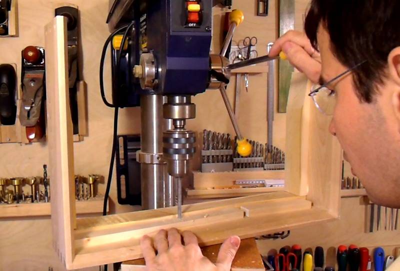
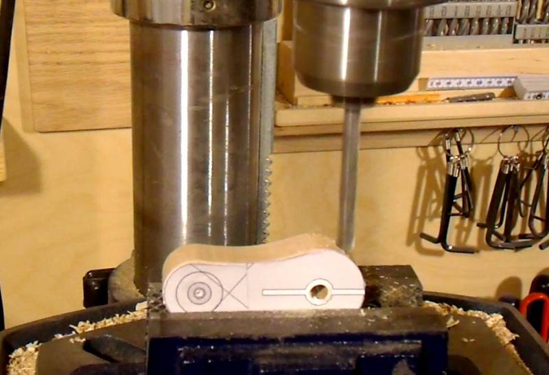
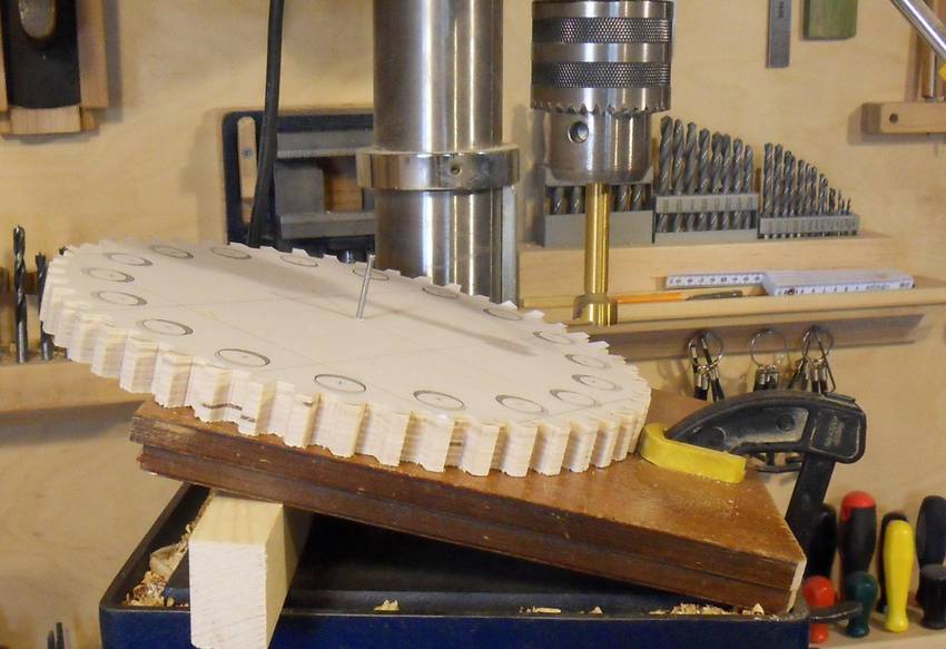 Next I drill the holes for the marbles. These holes need to be drilled at about
a 12.5 degree angle, as you can see in the setup here.
The angle of the holes causes the marbles to roll
into the wheel on the bottom side, and out of the wheel on the top side.
Next I drill the holes for the marbles. These holes need to be drilled at about
a 12.5 degree angle, as you can see in the setup here.
The angle of the holes causes the marbles to roll
into the wheel on the bottom side, and out of the wheel on the top side.
I never tilt the drill press table because it's just too much bother to adjust it and then get it back to dead square afterwards, instead I use a wedge or an inclined piece of wood to provide an angled support.
I drilled a small pilot hole in the middle of the wheel. A nail stuck in this hole and driven into the support piece helps to keep the wheel aligned.
 The 3/4" (19 mm) drill bit needs to be set to a depth where it just barely doesn't cut
through to the other side of the wheel. (18 mm will also work as well for the hole diameter,
for metric countries.)
The marbles are 16 mm in diameter and need to sink fully into the 3/4" (19 mm) thick plywood.
The 3/4" (19 mm) drill bit needs to be set to a depth where it just barely doesn't cut
through to the other side of the wheel. (18 mm will also work as well for the hole diameter,
for metric countries.)
The marbles are 16 mm in diameter and need to sink fully into the 3/4" (19 mm) thick plywood.
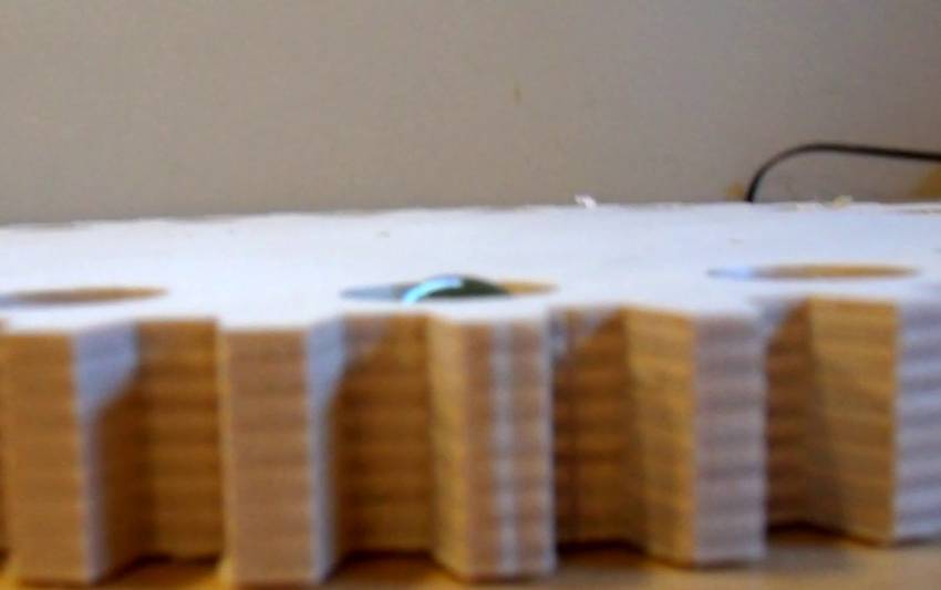 Because the 3/4" (19 mm) holes are not flat at the bottom, and are at an angle, the marbles
won't actually fit entirely into the holes.
Because the 3/4" (19 mm) holes are not flat at the bottom, and are at an angle, the marbles
won't actually fit entirely into the holes.
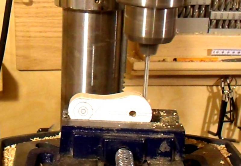
 The solution is to drill another hole 1/2" (12 mm) in diameter all the way through
in the middle of each hole. I used the same setup that I used to drill the
other holes. This helps to get the smaller holes in the center of the larger ones, at least
in terms of distance from the wheel center.
The solution is to drill another hole 1/2" (12 mm) in diameter all the way through
in the middle of each hole. I used the same setup that I used to drill the
other holes. This helps to get the smaller holes in the center of the larger ones, at least
in terms of distance from the wheel center.
The smaller holes aren't big enough for the marbles to roll out the back, but they add room so that the marbles now fit all the way into the holes.
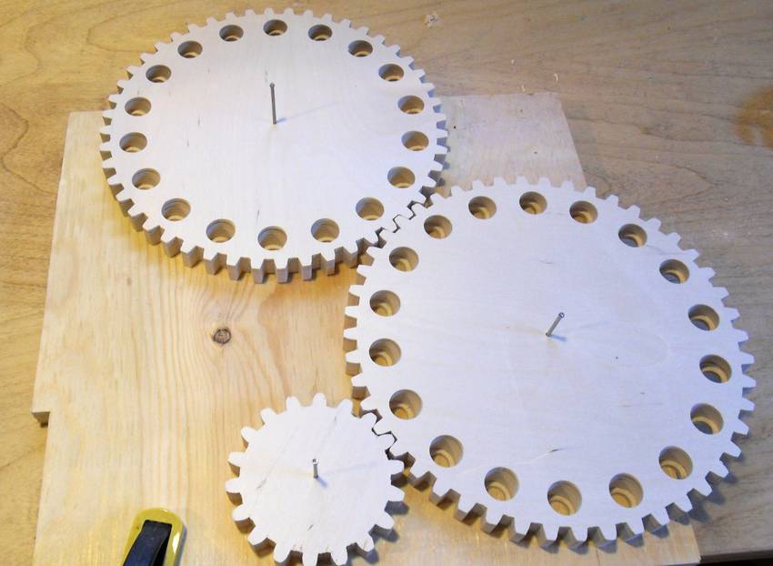 I used the same procedure for the teeth on the small drive gear as I used on the
larger gears.
The drive gear will be on the same shaft as the crank, and turning it clockwise
will turn the other two wheels in the appropriate directions.
I used the same procedure for the teeth on the small drive gear as I used on the
larger gears.
The drive gear will be on the same shaft as the crank, and turning it clockwise
will turn the other two wheels in the appropriate directions.
I have the gears meshing to the full depth of the teeth. Keep in mind that on the actual machine, the gears don't need to mesh to the full tooth depth.
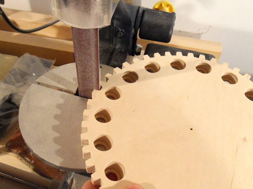 A small strip sander can be handy for tweaking the shape of the gear teeth
if there is any binding. You can also use a file or a thin strip of wood
with sandpaper wrapped around it.
A small strip sander can be handy for tweaking the shape of the gear teeth
if there is any binding. You can also use a file or a thin strip of wood
with sandpaper wrapped around it.
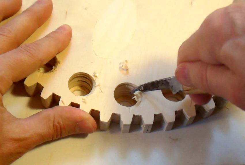 An optional step is to flare out the holes towards the leading edge. This allwos marbles
to glide into the holes when the gears are cranked faster. That way, the marble
machine can bring marbles to the top even faster.
An optional step is to flare out the holes towards the leading edge. This allwos marbles
to glide into the holes when the gears are cranked faster. That way, the marble
machine can bring marbles to the top even faster.
The flares need to go on the leading edge of the holes. With the gears turning in opposite directions, just carve the flares on the clockwise-side on one gear, and on the counterclockwise side in the other gear. When assembling the machine, be sure that the gear with the counterclockwise side flares is mounted in the lower position.
Mounting the wheels
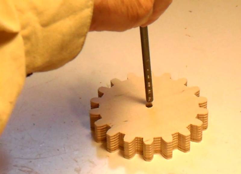
 I neglected to drill the holes for the drive shaft in the base box parts, so here I'm drilling
the shaft hole in the assembled box. If you drill the shaft hole ahead of time,
you will still need to re-drill it because the ledge that holds the machine's
tilted floor in place will have covered it up.
I neglected to drill the holes for the drive shaft in the base box parts, so here I'm drilling
the shaft hole in the assembled box. If you drill the shaft hole ahead of time,
you will still need to re-drill it because the ledge that holds the machine's
tilted floor in place will have covered it up.
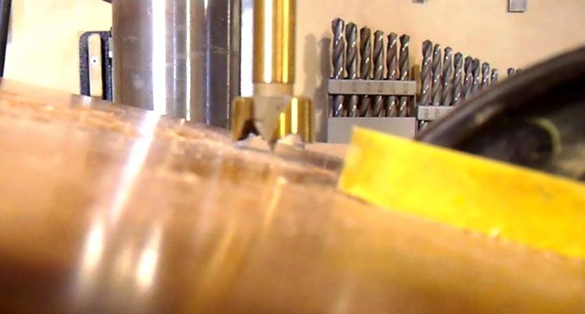
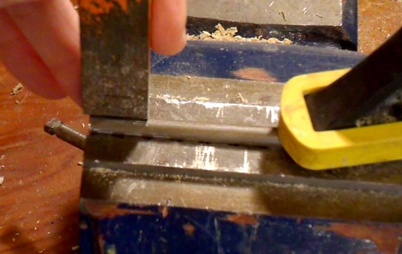 Here I'm roughening up the end of the shaft. I'm making some grooves in it
with a cold chisel. The shaft is also resting against the edges of the
hardened vise jaws, which will make additional score lines.
Here I'm roughening up the end of the shaft. I'm making some grooves in it
with a cold chisel. The shaft is also resting against the edges of the
hardened vise jaws, which will make additional score lines.
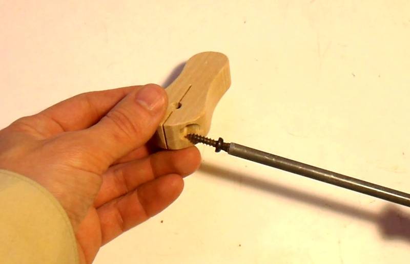
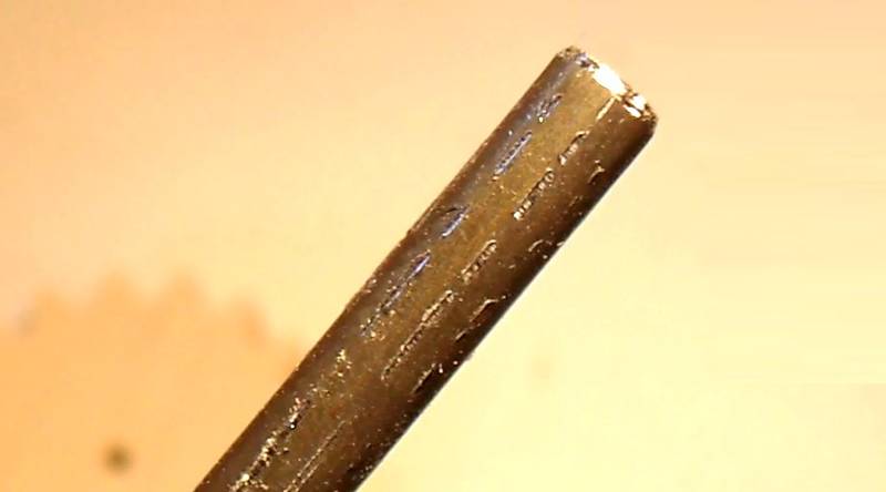 The score lines in the shaft. These will give better grip in the gear.
I also ground a bevel onto the end of the shaft to make it easier to hammer
it into the drive gear.
The score lines in the shaft. These will give better grip in the gear.
I also ground a bevel onto the end of the shaft to make it easier to hammer
it into the drive gear.
 I drilled a 15/64" hole for the 1/4" shaft (in metric units, roughly like a 5.5 mm hole
for a 6 mm shaft). That makes for a tight press fit, and it takes
a bit of hammering to get it in.
I drilled a 15/64" hole for the 1/4" shaft (in metric units, roughly like a 5.5 mm hole
for a 6 mm shaft). That makes for a tight press fit, and it takes
a bit of hammering to get it in.
 I cut the basic shape of the crank handle out on the bandsaw.
Here's starting a hole on the side for the screw to lock it on the shaft.
I cut the basic shape of the crank handle out on the bandsaw.
Here's starting a hole on the side for the screw to lock it on the shaft.
It would have been easier to drill that hole before cutting the curves of the handle shape. I pushed the drill all the way in the chuck, and I am using a drill press vise to steady the work piece as I start the hole. The angled surface tends to pull the drill to the side. But with the drill press vise clamped to the table, it was possible to get the hole in.
 I drilled that previous hole to serve as a countersink for the screw head.
Next, I drill a shank hole, larger than the screw's major
thread diameter. This hole goes to a depth of half-way across the handle.
I drilled that previous hole to serve as a countersink for the screw head.
Next, I drill a shank hole, larger than the screw's major
thread diameter. This hole goes to a depth of half-way across the handle.
After that, I use a drill just smaller than the screw's major thread diameter and drill all the way through.
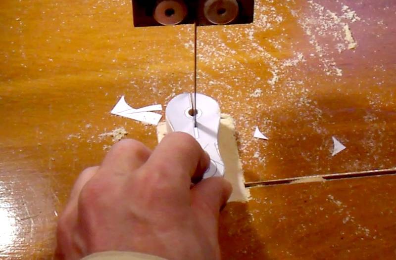 Now cutting the slot in the crank. This slot divides the shaft part of the
crank in two.
Now cutting the slot in the crank. This slot divides the shaft part of the
crank in two.
 A flat head (as opposed to countersink) screw pulls the halves of the crank
together to clamp it onto the drive shaft.
A flat head (as opposed to countersink) screw pulls the halves of the crank
together to clamp it onto the drive shaft.
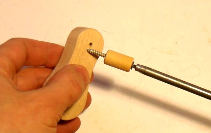 Now adding the crank handle knob. I'm using a screw that has a smooth shank (obscured
by the knob in this photo). The knob is just a short piece of dowel with a
hole drilled through it, and a countersink on one end so that the screw head
sits below the surface.
Now adding the crank handle knob. I'm using a screw that has a smooth shank (obscured
by the knob in this photo). The knob is just a short piece of dowel with a
hole drilled through it, and a countersink on one end so that the screw head
sits below the surface.
The pilot hole in the crank is just a bit larger than the minor diameter of the screw. This makes for a tight fit - I don't want that screw to come loose.
I usually use longer screws cut to length to get screws with a smooth shank, but you need a grinder to cut the hard screws - too hard to saw. You could also use a 1.5" #6 machine screw. The threads on those are smooth enough that you don't need a smooth shank. With effort, machine screws will thread into unthreaded holes in wood that are just smaller than the screw.
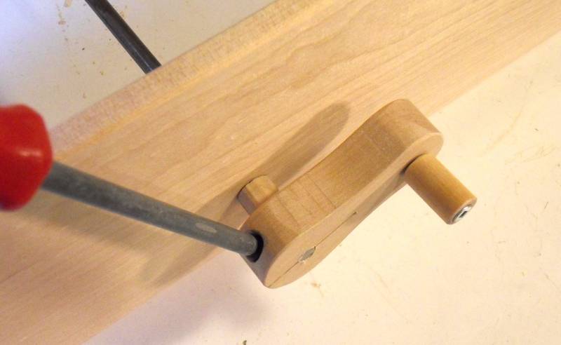 A small wooden spacer is put onto the shaft, then the crank handle, and then the screw is
tightened to lock it in place.
A small wooden spacer is put onto the shaft, then the crank handle, and then the screw is
tightened to lock it in place.
The spacer behind the crank is just a 12 mm thick piece of wood with a 17/64" hole (just larger than the shaft) in it, then cut to a cylinder on the bandsaw.
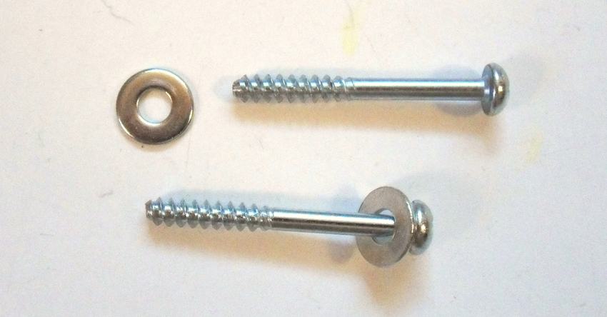 The wheels themselves just turn on screws. I used some longer screws, cut to length
to get screws with a sufficiently long smooth shank.
The wheels themselves just turn on screws. I used some longer screws, cut to length
to get screws with a sufficiently long smooth shank.
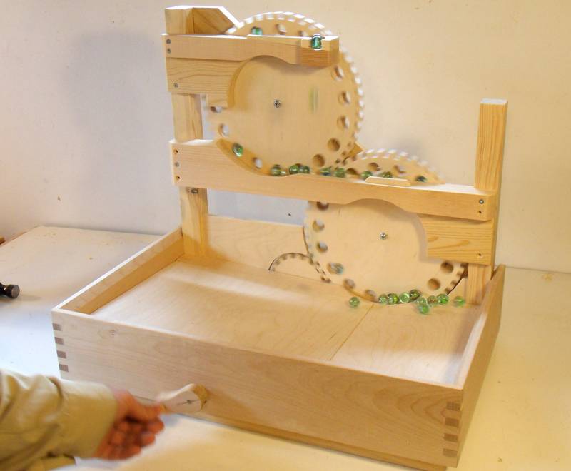 Even without any of the noise makers, just the elevating wheels and marbles dropping
down, the machine makes quite a racket. Fun to crank!
Even without any of the noise makers, just the elevating wheels and marbles dropping
down, the machine makes quite a racket. Fun to crank!
Next: Building the elevating mechanism
Back to Marble machine 2.1