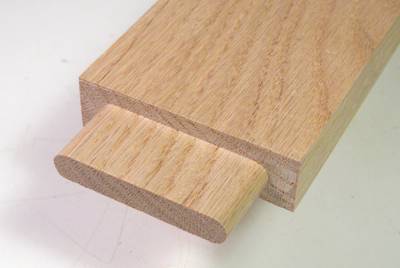
 tenons that are trimmed on all sides, including rounding both ends to perfectly
fit the rounded slot mortises from a slot mortiser such as my
homemade slot mortiser
tenons that are trimmed on all sides, including rounding both ends to perfectly
fit the rounded slot mortises from a slot mortiser such as my
homemade slot mortiser
The best way to produce tenons with rounded edges would be to cut them with a router. The router would need to be guided by some sort of template system to trace the curves.
There are two systems that I know of that use a router and templates to cut rounded tenons. One is the rather expensive multirouter, the other a still not very cheap Leigh FMT jig
One thing that's interesting about the Leigh FMT jig is that the templates have a different shape from the actual tenon because the mechanism stretches the tenon along one axis.
 Seeing that I don't have a machine shop to make accurate metal parts,
I figured it would make sense to build a machine where the templates are
bigger than the final tenon. But unlike the Leigh FMT jig, I wanted
my templates to be bigger in both the X and Y axis, so that
my template would just be a bigger version of the final shape instead of
some distorted shape.
Seeing that I don't have a machine shop to make accurate metal parts,
I figured it would make sense to build a machine where the templates are
bigger than the final tenon. But unlike the Leigh FMT jig, I wanted
my templates to be bigger in both the X and Y axis, so that
my template would just be a bigger version of the final shape instead of
some distorted shape.
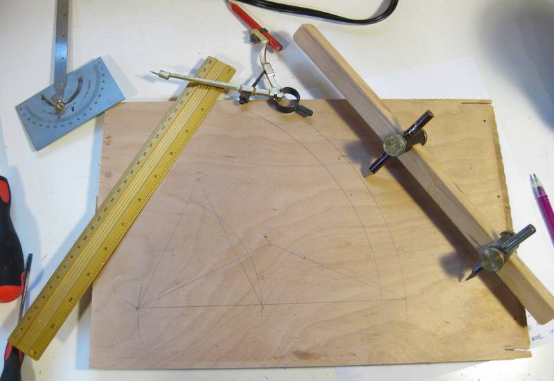
A good mechanism for stretching and offsetting an image is a pantograph, so I decided to make my whole machine based on a pantograph mechanism. That required some thought as to how to go about it. CAD can be very useful for making detailed refinements to a design, but when inventing a totally new mechanism, I prefer to actually play with some bits of wood to try it out.
So I started experimenting with the geometry with a compass, ruler, protractor, and some trammel points.
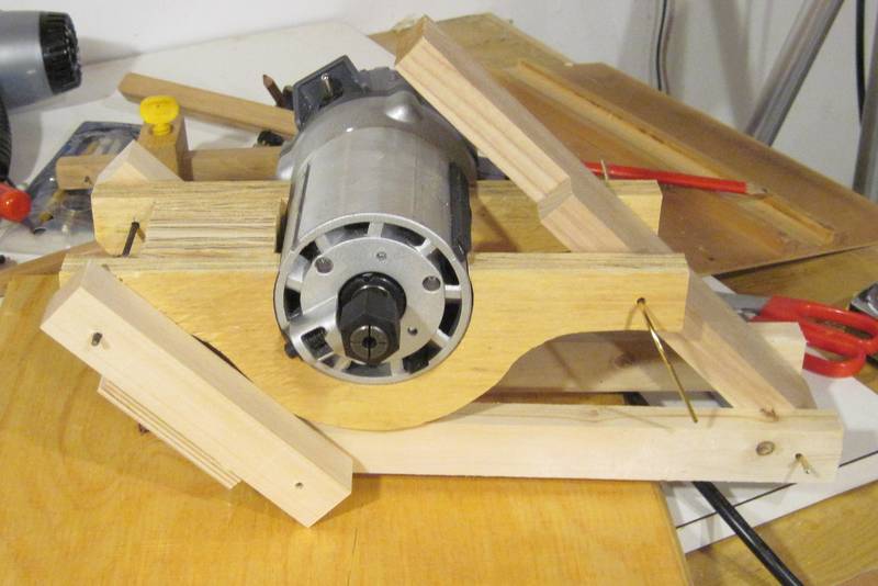
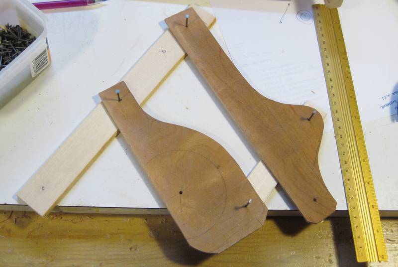 My original idea was to have the axis of the router horizontal, with the weight
of the router supported by the pantograph. The pantograph's fixed point, or origin
would be on the left, the router in the middle, and my template to the right.
My original idea was to have the axis of the router horizontal, with the weight
of the router supported by the pantograph. The pantograph's fixed point, or origin
would be on the left, the router in the middle, and my template to the right.
I cut up some scraps of wood to try out the geometry. I offset one of the links of my pantograph to get it out of the way.
But I found that my horizontal range of motion would be very restricted. The pantograph itself allowed the router to move a fair distance, but I found that my router would quickly bump up against where I'd want to put the template, so the usable range of motion was much less. Much head scratching ensued. I realized that I didn't have this problem when moving the router in the vertical direction, so maybe I should mount the stock vertically?
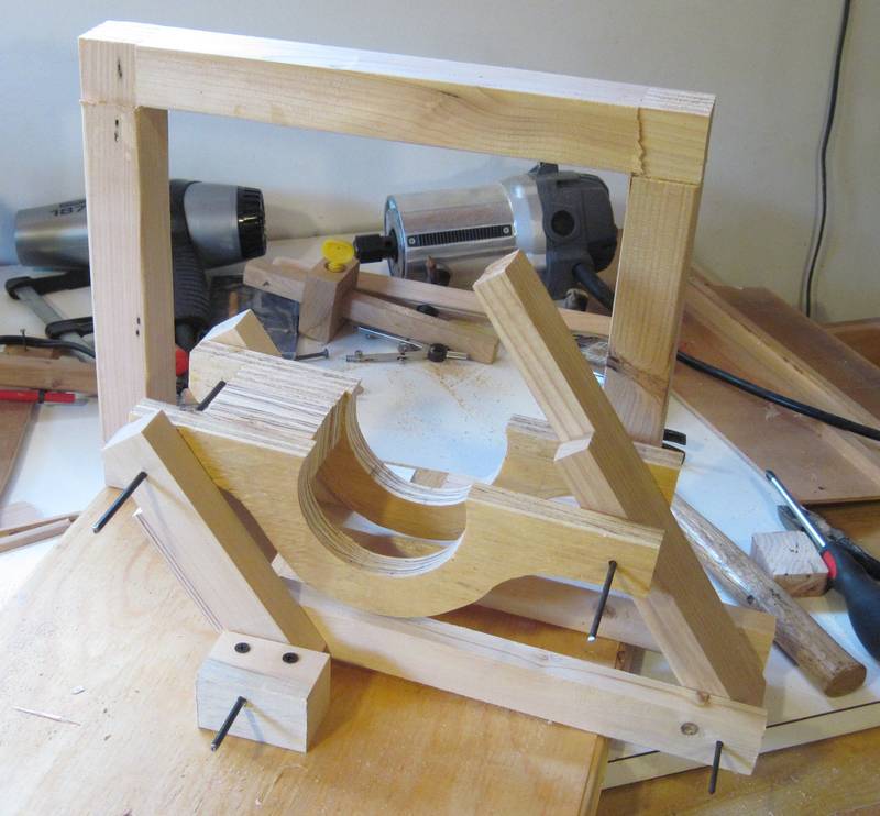
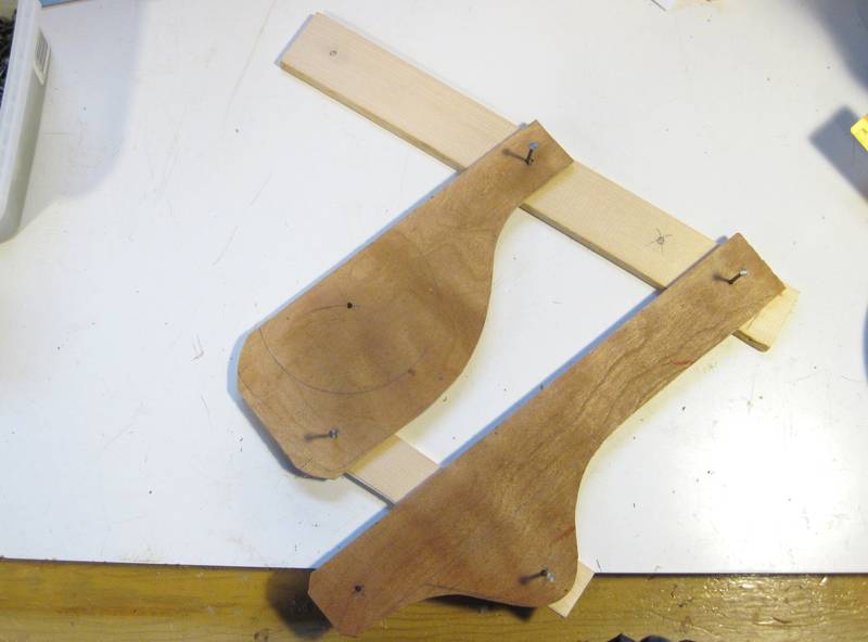 Playing around with my bits of wood, I realized if I turned my pantograph 90
degrees, so that the template would be above
the router, I could have a lot of horizontal range of motion without the router
bumping into my template. The restriction would now be on the vertical range
of motion, but I figured horizontal range would be more important. When cutting
tenons, the board would typically be horizontal, and much less high (thick)
than wide.
Playing around with my bits of wood, I realized if I turned my pantograph 90
degrees, so that the template would be above
the router, I could have a lot of horizontal range of motion without the router
bumping into my template. The restriction would now be on the vertical range
of motion, but I figured horizontal range would be more important. When cutting
tenons, the board would typically be horizontal, and much less high (thick)
than wide.
With this layout, I also wouldn't need to offset the one link anymore. So at least in terms of geometry and interference, this concept should be a bit simpler than my first idea.
 So I set out to build a proof of concept of the machine. I used some really
cheap 3/4" plywood that used to be a packing crate,
and some scraps of wood lying around my workshop.
So I set out to build a proof of concept of the machine. I used some really
cheap 3/4" plywood that used to be a packing crate,
and some scraps of wood lying around my workshop.
 I mounted this on another piece of scrap plywood, and made a frame to go behind
my mechanism to hold the template.
I mounted this on another piece of scrap plywood, and made a frame to go behind
my mechanism to hold the template.
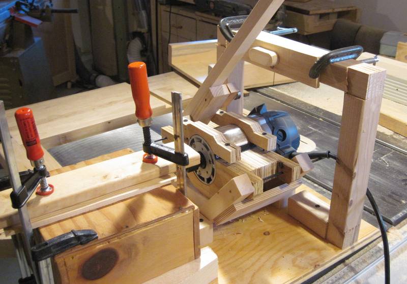 I would also need to build some sort of work table to hold the stock at
the right height in front of the router. But I was still exploring the feasibility
of the overall concept, so I stacked some boxes in front of my router
and clamped everything down with some bar clamps.
I would also need to build some sort of work table to hold the stock at
the right height in front of the router. But I was still exploring the feasibility
of the overall concept, so I stacked some boxes in front of my router
and clamped everything down with some bar clamps.
I also made a simple template and clamped that to the frame with some C clamps.
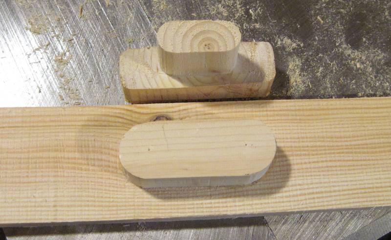 Here's my first tenon, with the template I used to cut it below.
So the concept appeared to be workable. I was disappointed with the accuracy I got from it, but then again, I had just cobbled together a few rough pieces of wood to test the concept. I hadn't even attempted to make this machine rigid or precise.
I had originally oriented my machine so that the operating lever was to the right, similar to how it is on my slot mortiser.
I found the machine a little tiring to operate because I always had to pull up on the operating lever to counteract the weight of my router. I also found myself putting my left hand on the work table to counteract the force. So it would be good to have a hand hold for the left hand somehow. But my full machine would also have plunge lever, so that should also act as my left hand hold.
 So I needed a plunge lever to the left of my main operating lever. The best
way to achieve that was to move the main operating lever to be on the left side,
and put the plunge lever behind it.
So I needed a plunge lever to the left of my main operating lever. The best
way to achieve that was to move the main operating lever to be on the left side,
and put the plunge lever behind it.
I also wanted to add some springs to counteract the weight of the router so that I wouldn't get tired from pulling up on the operating lever anymore.
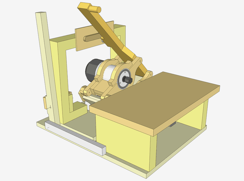
Having worked out the feasibility of the concept, I drew up a CAD model of the machine. The CAD model was very useful in terms of working out range of motion and interference issues with my machine.
Back to my woodworking website