 One time, while the dryer was running, I held the cable providing power to the
clothes dryer and noticed it was slightly warmer than the others.
One time, while the dryer was running, I held the cable providing power to the
clothes dryer and noticed it was slightly warmer than the others.
One time, while the dryer was running, I held the cable providing power to the
clothes dryer and noticed it was slightly warmer than the others.
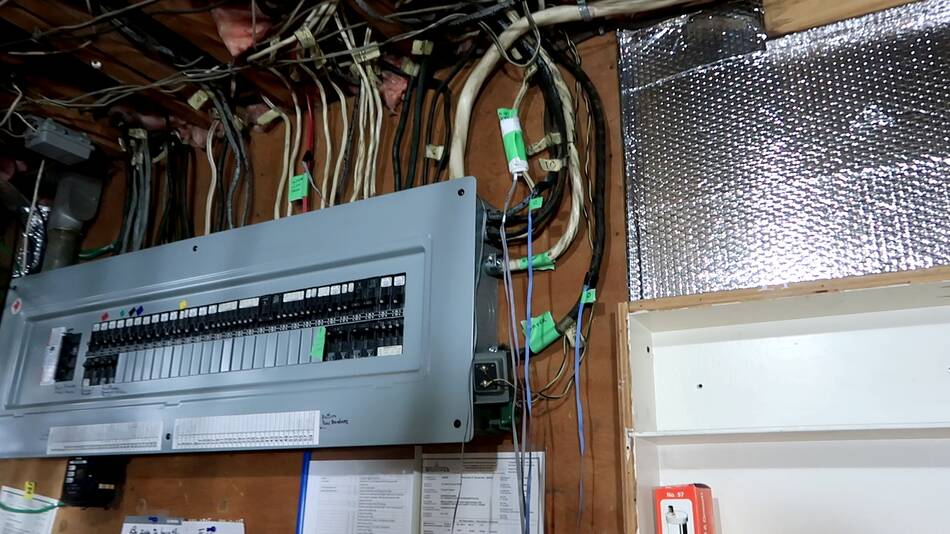
And since I already had four BMP280 sensors hooked up to a Raspberry Pi, I taped those to some of the wires to see if I could measure the temperature rise.
Sure enough, I can see the wires warm up when various high power appliances turn on and off.
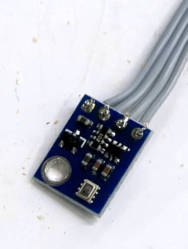 At right, a BMP280 sensor eval board. The sensor itself is the shiny part
next to the round hole on the circuit board.
At right, a BMP280 sensor eval board. The sensor itself is the shiny part
next to the round hole on the circuit board.
 Hot water heaters tend to be rated at 4 kilowatts, but I only got slight
warming of the cable leading to ours, and it seemed like it was on most
of the time.
Hot water heaters tend to be rated at 4 kilowatts, but I only got slight
warming of the cable leading to ours, and it seemed like it was on most
of the time.
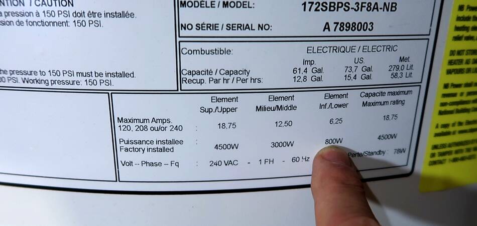
Then I checked the label on it, the lower element is just 800 watts.
This is kind of clever. The lower element does most of the heating. With it being fairly low power, it usually takes until after midnight to get back up to temperature after bath time. So much of the power use is during off peek times. The tank is owned by NB power, our utility company, and using electricity off-peak saves them money!
But if it starts to run out of hot water, the top element kicks in, and that's one is 4 kilowatts.
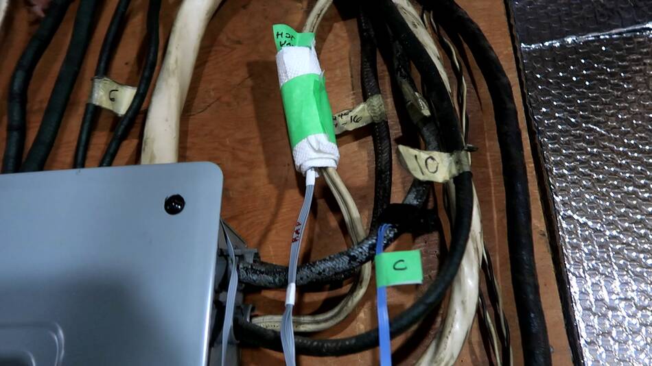 Anyway, that 800 watts is only about 3.5 amperes at 240 volts, and with a #12
wire that only warms the wire by a fraction of a degree. I wrapped some insulating
material around the wire to get a better reading.
Anyway, that 800 watts is only about 3.5 amperes at 240 volts, and with a #12
wire that only warms the wire by a fraction of a degree. I wrapped some insulating
material around the wire to get a better reading.
But just turning on the light near the breaker panel on also changes the temperature by more than the hot water heater cable warms up. So I swapped out the 100-watt incandescent for for an LED bulb.
But In the winter, when the old oil furnace comes on this room gets quite warm, so that will totally swamp out the signal.
 And I also wanted to monitor more than four circuits, and connecting more
than four bmp280 sensors to a Raspberry Pi gets complicated.
And I also wanted to monitor more than four circuits, and connecting more
than four bmp280 sensors to a Raspberry Pi gets complicated.
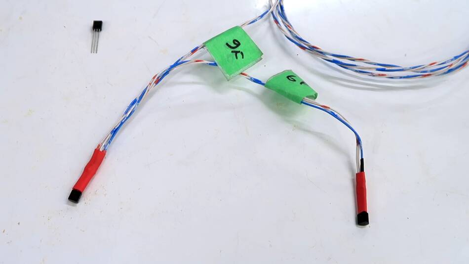
So I used some of these cheap 1-wire ds18b20 sensors I bought of eBay. You can hook up a lot of these all on the same 1-wire bus.
And I put the probes on the wires further from the heating system. I also have a few to measure the ambient temperature to better judge small temperature rise in the wire, without having to rely on my judgement.
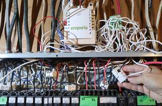
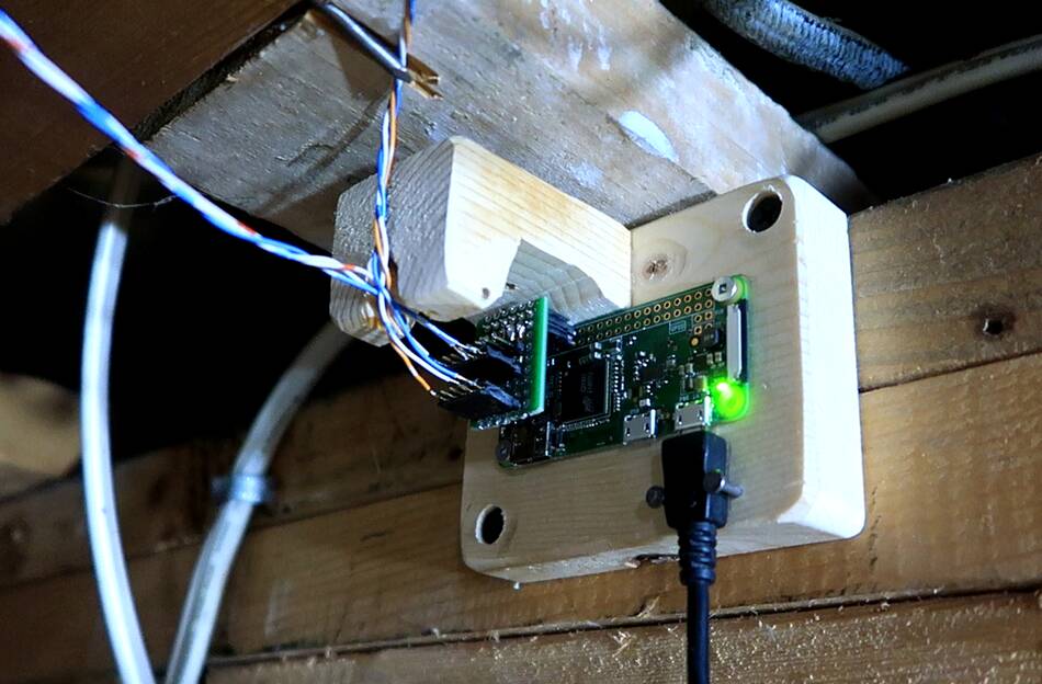 Here's a Raspberry Pi Zero-W mounted close to the ceiling. I made a small adapter
board to allow me to plug multiple chains of these ds18b20 sensors into it.
Here's a Raspberry Pi Zero-W mounted close to the ceiling. I made a small adapter
board to allow me to plug multiple chains of these ds18b20 sensors into it.
 But these cheap 18B20 sensors, like a lot of components from eBay, Aliexpress
Amazon are cheap Chinese imitations of the real thing. They readings are noisy
and not very accurate. But worse, once in a while, they end up latching up in
a way required powering them down to work again. Just soft rebooting the
Raspberry Pi wouldn't bring them back.
But these cheap 18B20 sensors, like a lot of components from eBay, Aliexpress
Amazon are cheap Chinese imitations of the real thing. They readings are noisy
and not very accurate. But worse, once in a while, they end up latching up in
a way required powering them down to work again. Just soft rebooting the
Raspberry Pi wouldn't bring them back.
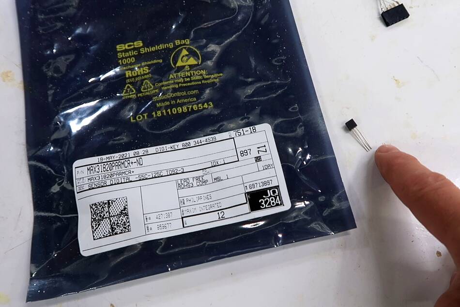
So I bought some genuine sensors from Maxim off of Digikey. They cost 10x as much. I think these are the most accurate sensors I have. And they don't latch up. They sometimes fail to give me a reading, but that's easy enough to retry in software.
My BMP280 sensors are also Chinese imitations, no doubt. They aren't very good in terms of absolute accuracy, but they do produce very clean signals.
I like how this is a cheap non invasive way of monitoring current flow in wires.
But the cool thing is, if you are looking at fractions of a degree temperature changes, just about everything produces a measurable temperature change. You can use temperature sensors to measure a lot of things, like room occupancy, doors open, and just about anything that uses electricity.
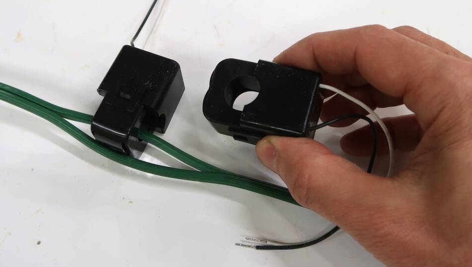 Of course, there are better solutions for monitoring power, like these clamp on
current transformers, but I'd have to split the wires into individual conductors, or
mount them in the breaker panel, so it's not exactly non-invasive.
And then I'd still need to run the signal through an A/D converter to
get a reading.
Of course, there are better solutions for monitoring power, like these clamp on
current transformers, but I'd have to split the wires into individual conductors, or
mount them in the breaker panel, so it's not exactly non-invasive.
And then I'd still need to run the signal through an A/D converter to
get a reading.
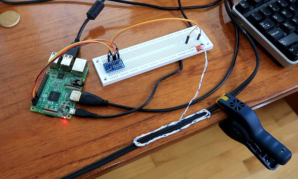 But I have been experimenting with inductively measuring current in a wire
just with a wire loop. My proof of concept suggests this should work, and should
be able to detect current in the wire down to about 1 ampere.
I'm not sure if I'll pursue this further.
But I have been experimenting with inductively measuring current in a wire
just with a wire loop. My proof of concept suggests this should work, and should
be able to detect current in the wire down to about 1 ampere.
I'm not sure if I'll pursue this further.
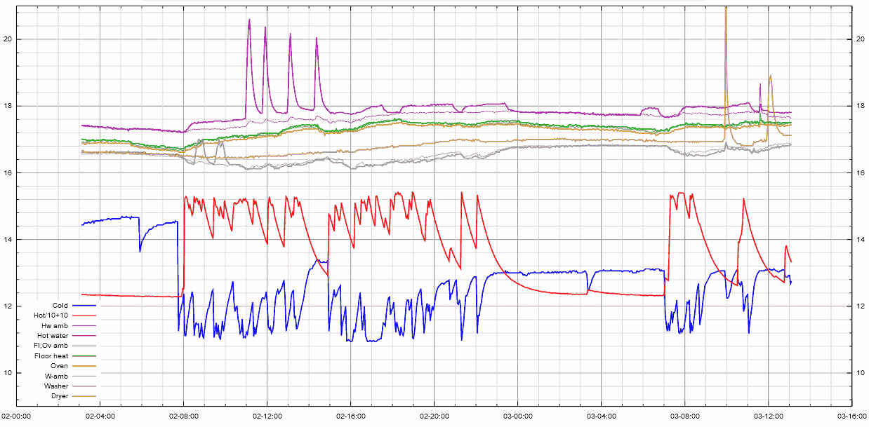
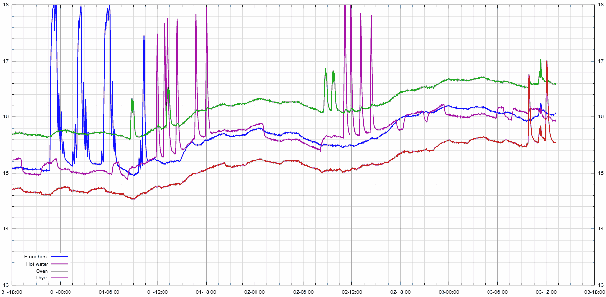 And finally, some graphs. Here three days of readings from the BMP280 sensors
next to the breaker panel. You can see how ambient temperature changes cause
the signals to drift, so this would tricky to interpret by computer.
And finally, some graphs. Here three days of readings from the BMP280 sensors
next to the breaker panel. You can see how ambient temperature changes cause
the signals to drift, so this would tricky to interpret by computer.
The purple line is the hot water heater wire, which jumps up and down by about 0.2 degrees (Celsius) as the 800 watt element turns on and off. Also much spikes in temperature rise as the higher power elements turn on.
Temperature rise in the wire is proportional to current squared, as an doubling in current also causes a doubling in voltage drop in the wire, so four times the energy loss in the wire.
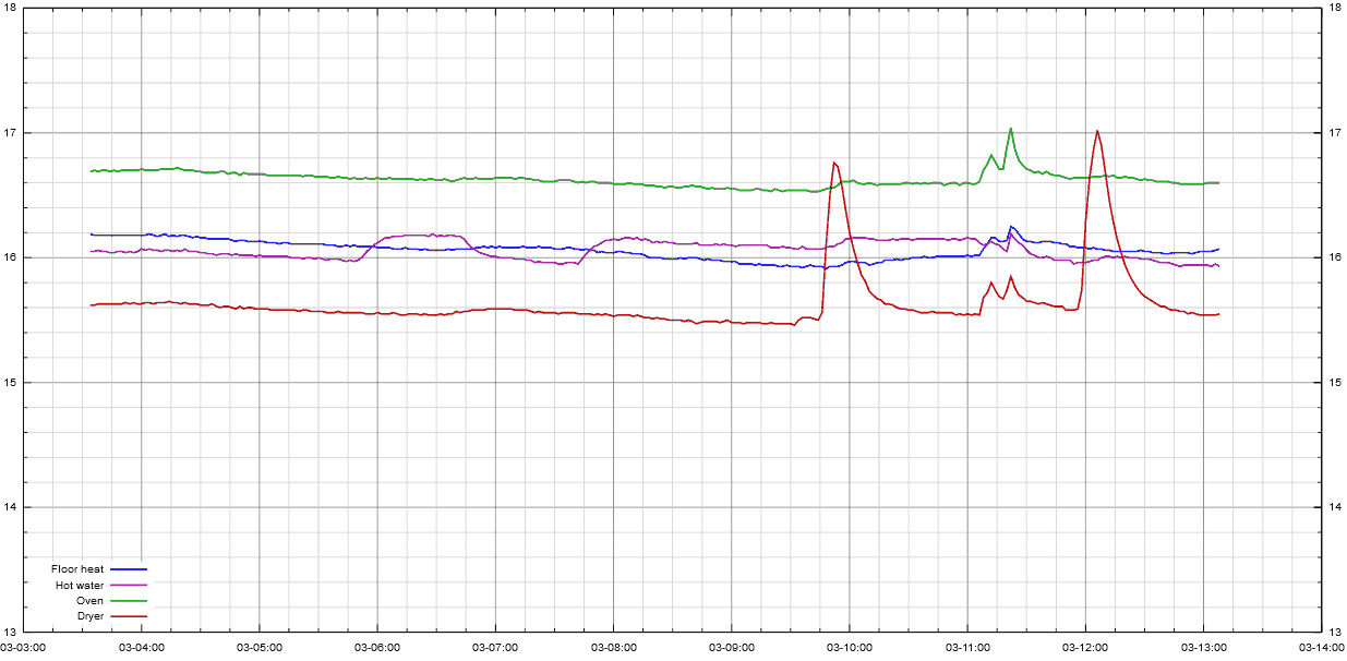 The same graph, but just showing the last few hours.
The small double spike on all the signals is from me standing in front of the breaker panel and filming the video. Just being near these temperature sensors causes a measurable rise in temperature.
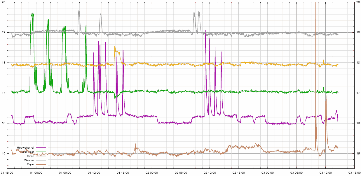
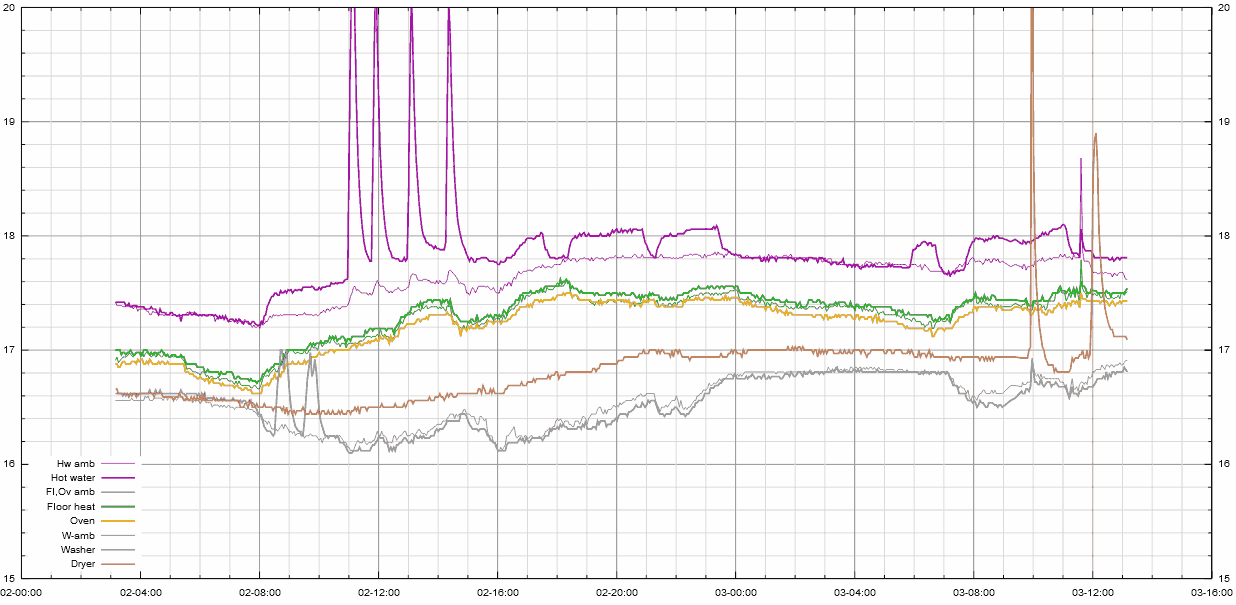 This graph is from my 19b20 sensors (the brand name ones, not the clones).
The tin lines are ambient measurements near the sensors themselves,
so compensating for ambient doesn't involve guesswork.
This graph is from my 19b20 sensors (the brand name ones, not the clones).
The tin lines are ambient measurements near the sensors themselves,
so compensating for ambient doesn't involve guesswork.
I read each sensor four times in a row and average to get a cleaner signal and slightly more resolution. The sensors only read out to 1/16th of a degree C.
 I also put a temperature sensor on the hot water pipe above the water heater
and another on the cold water pipe coming into the house. When hot water is
used, the hot water pipe warms up, then cools slightly. The cold water coming
into the house does the opposite.
I also put a temperature sensor on the hot water pipe above the water heater
and another on the cold water pipe coming into the house. When hot water is
used, the hot water pipe warms up, then cools slightly. The cold water coming
into the house does the opposite.
I applied a scaling factor to the hot water pipe temperature to make it fit, the water coming out of the tank is at about 60°C.
 And here, normalized readings for the wires, with ambient temperature subtracted.
The bottom-most channel doesn't have an ambient sensor very close to it, so it
move around a bit, but the cable to the dryer warms up by 2 degrees when the dryer
runs, which is more than the error in my estimate of ambient temperature.
And here, normalized readings for the wires, with ambient temperature subtracted.
The bottom-most channel doesn't have an ambient sensor very close to it, so it
move around a bit, but the cable to the dryer warms up by 2 degrees when the dryer
runs, which is more than the error in my estimate of ambient temperature.
Back to my Woodworking website
 Monitoring 16 circuits at the breaker panel
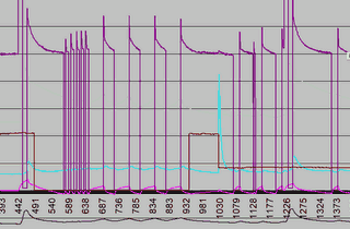 How efficient is a refrigerator heat pump? Experiments
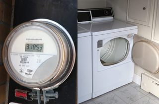 Using a utility meter to measure appliance power usage
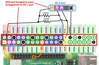 Using the second (I2C 0) port on Raspberry Pi
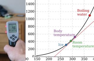 Measure R-values with infrared thermometer
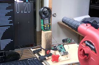 Anemometer interface for Raspberry Pi
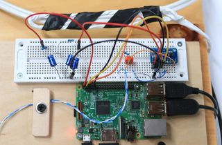 Inductive current measuring using Raspbery Pi
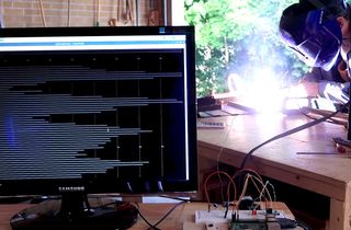 Measuring welder current with a computer
 How warm can I get my shed with a space heater?
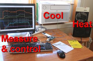 Window AC vs. space heaters: Measuring BTUs