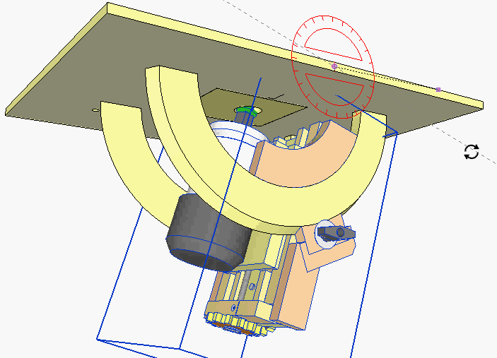
 My initial idea was to use trunnions as a tilt mechanism for the router lift,
especially because I'd just previously come up with an improved method for
making trunnions for my homemade bandsaw.
My initial idea was to use trunnions as a tilt mechanism for the router lift,
especially because I'd just previously come up with an improved method for
making trunnions for my homemade bandsaw.
But the design I came up with just seemed a bit unwieldy.
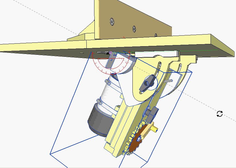 But router bits are wide and vary in shape, so there's no point in trying
to keep the bit aligned while rotating like you would a saw blade with a slot in the insert.
Considering how awkward the trunnion design looked, I decided to use hinges instead.
But router bits are wide and vary in shape, so there's no point in trying
to keep the bit aligned while rotating like you would a saw blade with a slot in the insert.
Considering how awkward the trunnion design looked, I decided to use hinges instead.
I have mixed feelings about the practicality of using CAD to actually come up with a new design, but in this case, I was able to reject an awkward design without wasting any wood.
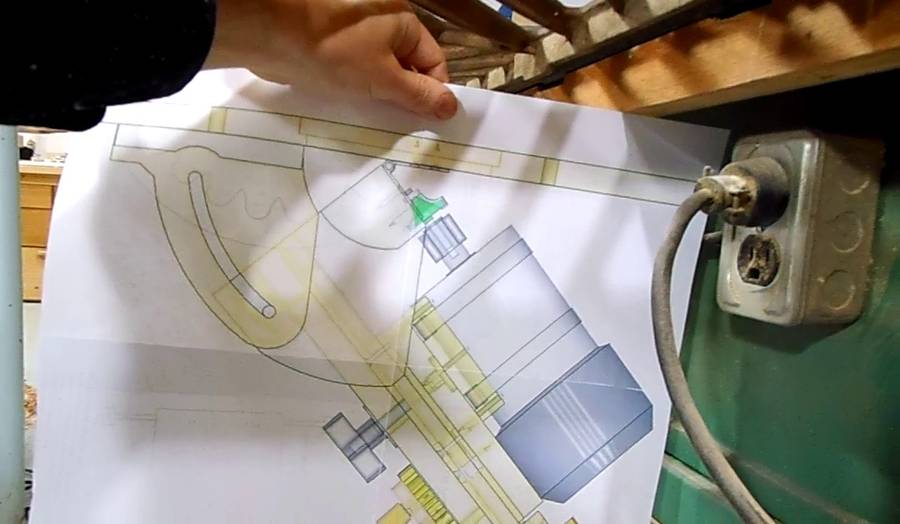 Next I used my BigPrint program to print
a large 1:1 picture of the lift onto four sheets of paper, which I glued together.
The 1:1 printout gives a better sense of scale. It was also handy for checking
how the tilting router lift would fit under the right extension wing of my
old table saw.
Next I used my BigPrint program to print
a large 1:1 picture of the lift onto four sheets of paper, which I glued together.
The 1:1 printout gives a better sense of scale. It was also handy for checking
how the tilting router lift would fit under the right extension wing of my
old table saw.
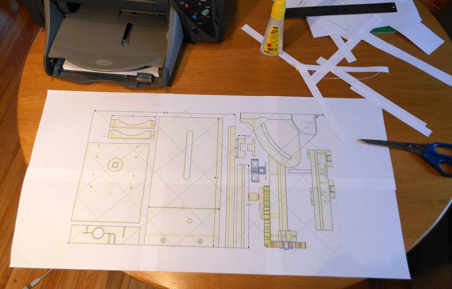 I started by making 1:1 printouts of the various parts from my CAD drawings
using my BigPrint program.
I started by making 1:1 printouts of the various parts from my CAD drawings
using my BigPrint program.
The 1:1 printouts are very useful as templates for cutting out the curved parts, but they are also useful for quickly checking rectangular parts for size. It helps to give a sense of scale and cuts down on measurement errors.
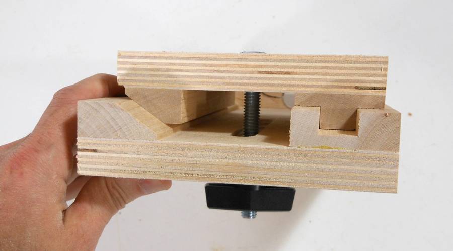 This shows the basic design of the sliding mechanism. A square channel
on one side ensures proper alignment, while a beveled track
on the other side always pushes the slider to one side so that any
play is always taken up on the same side when the knob is
tightened. This ensures consistency.
This shows the basic design of the sliding mechanism. A square channel
on one side ensures proper alignment, while a beveled track
on the other side always pushes the slider to one side so that any
play is always taken up on the same side when the knob is
tightened. This ensures consistency.
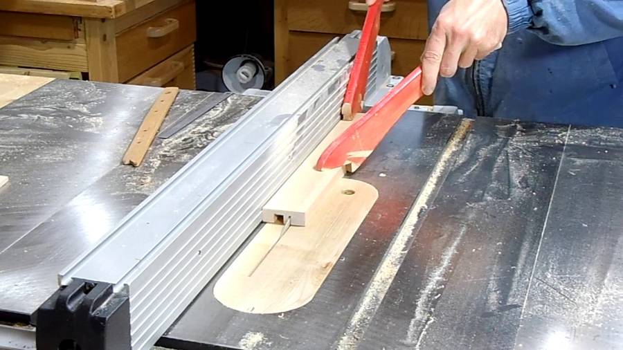 I cut out the square channels by making a series of cuts on the table saw.
It's hardly worth putting in the dado blade when making just one part.
By making individual cuts, I could tweak the width of the dado that I cut just
by bumping the fence by a tiny amount instead of having to mess with dado shims
for every adjustment.
I cut out the square channels by making a series of cuts on the table saw.
It's hardly worth putting in the dado blade when making just one part.
By making individual cuts, I could tweak the width of the dado that I cut just
by bumping the fence by a tiny amount instead of having to mess with dado shims
for every adjustment.
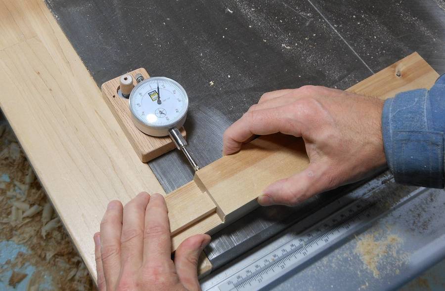 With the square channel cut, checking the amount of lateral play.
I had about 0.005" of play (0.12 mm). That was a bit more than I was aiming for, but it is necessary to have a few thou of play just to avoid jamming. Just a single coat of varnish on the rails would more than eliminate that amount of play, but I left these unvarnished. In my previous router lift, I initially varnished the rails, and they became too slippery to lock effectively, so I had to scrape the varnish off again.
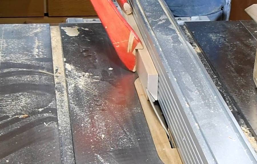 Cutting the 35 degree bevel for the beveled track. The 35 degree bevel needs
to be cut upright against the fence. It's important that the bevel still has a
bit of support on the table saw table.
Cutting the 35 degree bevel for the beveled track. The 35 degree bevel needs
to be cut upright against the fence. It's important that the bevel still has a
bit of support on the table saw table.
It would have been easier to start with a piece 2 cm thick instead of 1.6 cm, then cut the bevel, and after that, mill it down to its final thickness. That way there would have been a wider flat part of the workpiece on the table saw table for support.
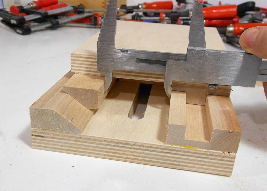 With the outer bevel track attached, the tricky part is getting the inner bevel track
at exactly the right lateral position so that the two pieces of plywood will be
parallel when pressed together.
With the outer bevel track attached, the tricky part is getting the inner bevel track
at exactly the right lateral position so that the two pieces of plywood will be
parallel when pressed together.
I made sure the two plywood pieces were parallel, pushed the inner bevel track out as far as I could (the beveled track left of the caliper is not glued yet), and then measured the remaining space between the two tracks.
I then made some spacer blocks to hold the inner bevel track at exactly the right position while I glued and clamped it all together.
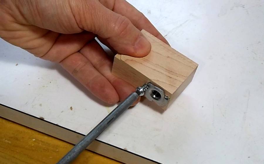 The sliding part of the lift is pushed up and down by a T-nut on a threaded
rod. As the rod turns, the nut is screwed up or down.
I added a screw to hold the T-nut in the wood. On my previous router lift,
I found that sometimes I forgot to unlock the knob when I cranked it down.
This had a tendency to pull the nut out of the wood, so a screw to hold it
in is a good idea.
The sliding part of the lift is pushed up and down by a T-nut on a threaded
rod. As the rod turns, the nut is screwed up or down.
I added a screw to hold the T-nut in the wood. On my previous router lift,
I found that sometimes I forgot to unlock the knob when I cranked it down.
This had a tendency to pull the nut out of the wood, so a screw to hold it
in is a good idea.
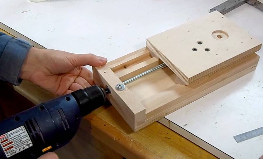 A quick test, spinning the threaded rod with a drill.
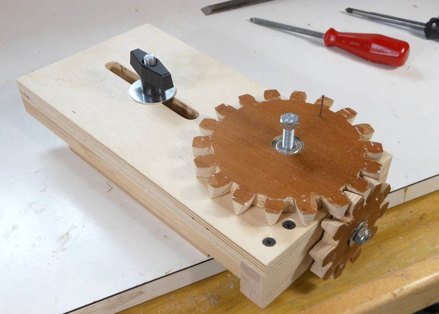 With the gears and locking knob attached.
 I wanted a nice number of turns per unit for this router lift. With an 18 turns per
inch threaded rod, if I had an 18:10 gear ratio, I would get exactly 10 turns per inch
of travel, or about 2.5 mm per turn. An easy number to remember.
I wanted a nice number of turns per unit for this router lift. With an 18 turns per
inch threaded rod, if I had an 18:10 gear ratio, I would get exactly 10 turns per inch
of travel, or about 2.5 mm per turn. An easy number to remember.
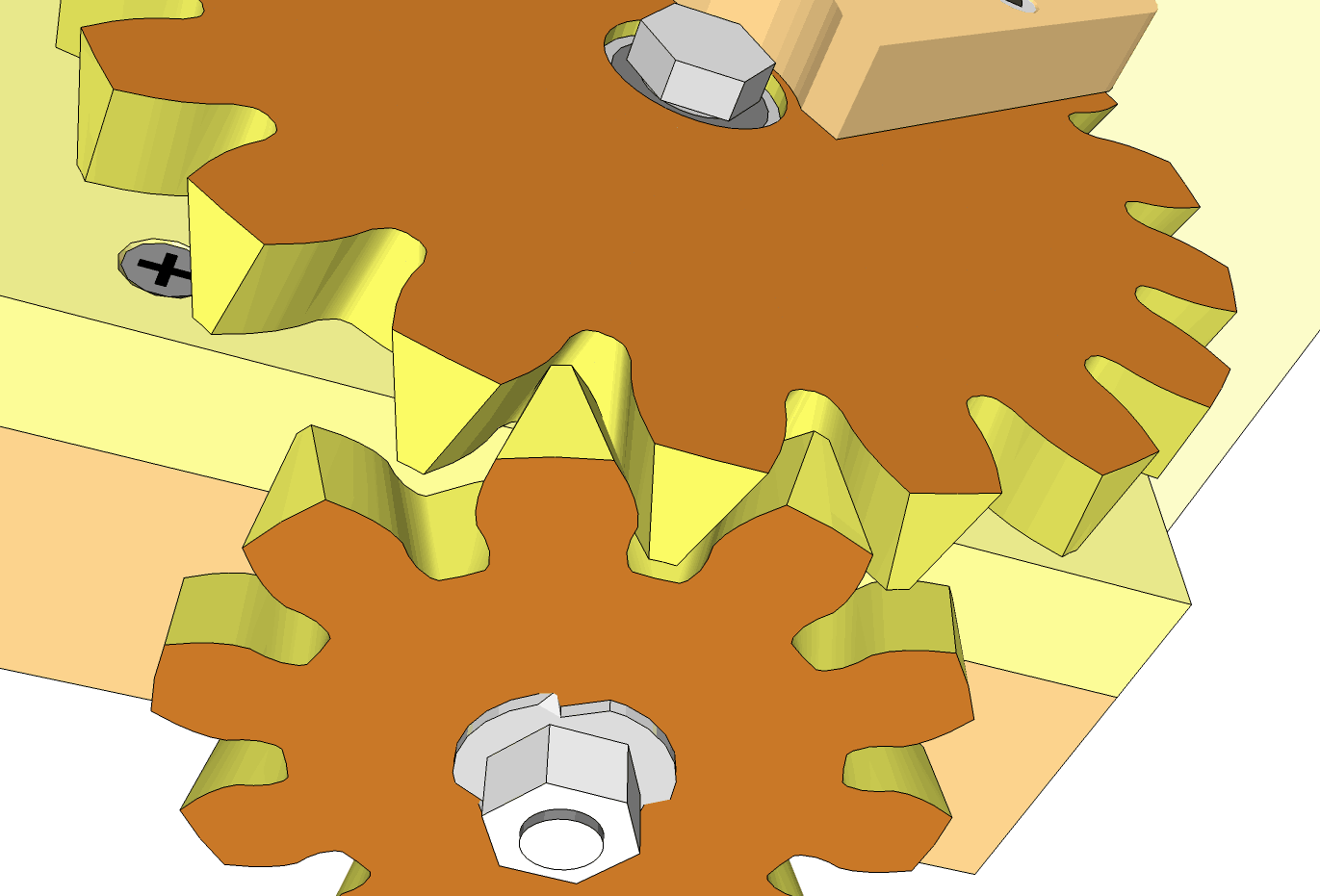
The most practical way to achieve this ratio was with an 18 tooth and a 10 tooth gear. But with only 10 teeth on the small gear, there was the risk that the fudged gear design I used on my previous router lift might run exceedingly rough. So I came up with a tapered tooth design that also works in theory, not just fudged a little in practice.
Basically, the sides of the teeth are beveled to match the pressure angle of the adjoining gear. This makes for a relatively elegant right angle meshing, and I checked that the gears would mesh in the CAD program before I built them. I have since added a feature to my gear program for making gears like this.
 The gears are designed to have a 14 degree pressure angle, and also have sides that are
beveled by 14 degrees towards the other gear. This required "fattening" the teeth
on the template so that they wouldn't taper to nothing on the other side.
The gears are designed to have a 14 degree pressure angle, and also have sides that are
beveled by 14 degrees towards the other gear. This required "fattening" the teeth
on the template so that they wouldn't taper to nothing on the other side.
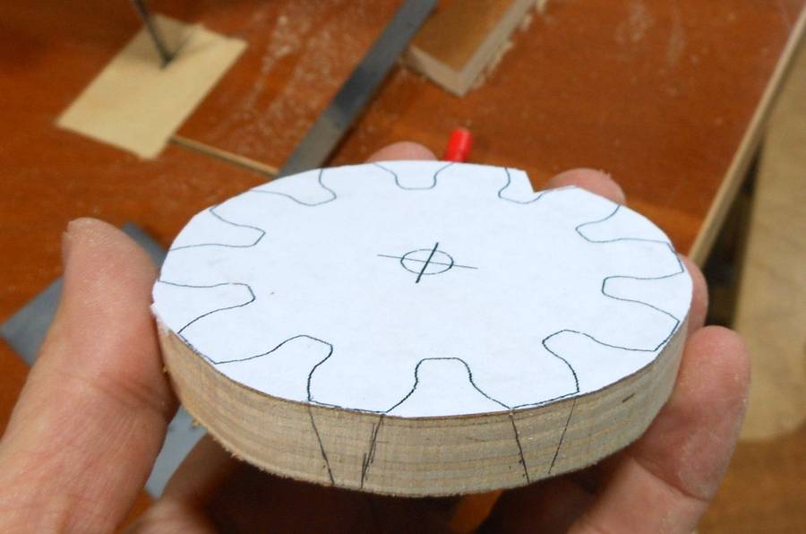
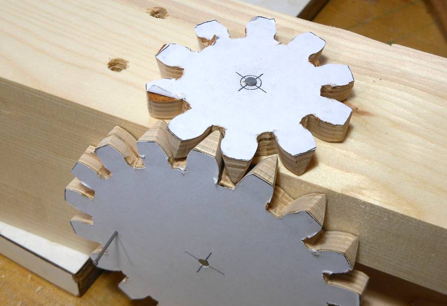
Shown here is my "fattened teeth" paper template glued onto the blank for the 10-tooth gear.
I'll include the fattened gear templates in the plans. If you use an M8 threaded rod (1.5 mm per turn), a good gear pairing would be 16 to 10, to give you exactly 2mm per crank turn. I'll include a 16-tooth template as well.
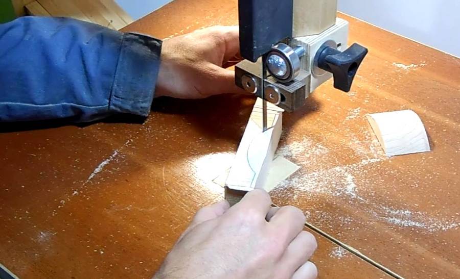
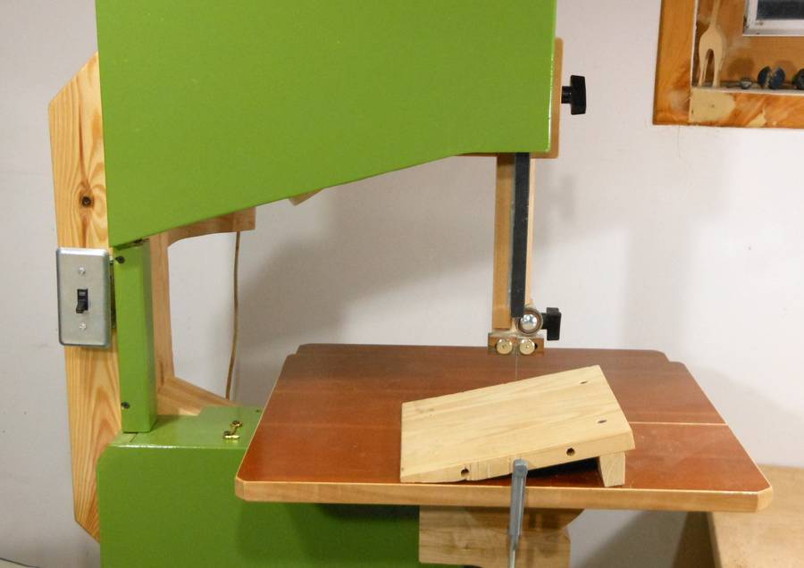 Cutting the teeth requires cutting angles slanted left and right on the bandsaw.
Most cast iron frame 14" bandsaws can tilt left by 15 degrees, but
my bandsaw does
not. So I used a small wedge clamped to the table to get the left tilt.
Cutting the teeth requires cutting angles slanted left and right on the bandsaw.
Most cast iron frame 14" bandsaws can tilt left by 15 degrees, but
my bandsaw does
not. So I used a small wedge clamped to the table to get the left tilt.
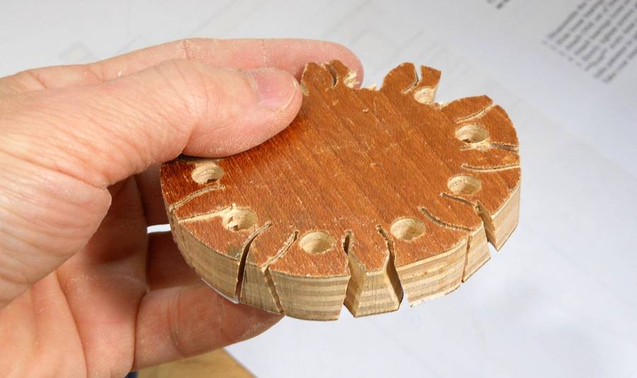 I drilled holes between the teeth, then cut the sides of the teeth,
following the lines on the template. The picture at left shows the bottom
side of the gear (template side down).
But because of the slants, the cuts don't fully line up with the holes on the other side,
so I had to make a few more cuts to free up the pieces.
I drilled holes between the teeth, then cut the sides of the teeth,
following the lines on the template. The picture at left shows the bottom
side of the gear (template side down).
But because of the slants, the cuts don't fully line up with the holes on the other side,
so I had to make a few more cuts to free up the pieces.
 I drilled small pilot holes in both cut gears, nailed them to a piece of timber,
and tested the design. Worked perfectly!
I drilled small pilot holes in both cut gears, nailed them to a piece of timber,
and tested the design. Worked perfectly!
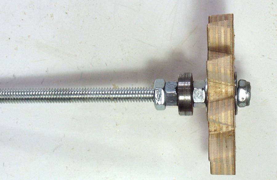 The small gear is mounted on the threaded rod. I inserted a T-nut into the
gear, then screwed that onto the threaded rod, with a nut on either side
to jam it in place. The roller skate ball bearing is also held in place
with a nut on either side.
The small gear is mounted on the threaded rod. I inserted a T-nut into the
gear, then screwed that onto the threaded rod, with a nut on either side
to jam it in place. The roller skate ball bearing is also held in place
with a nut on either side.
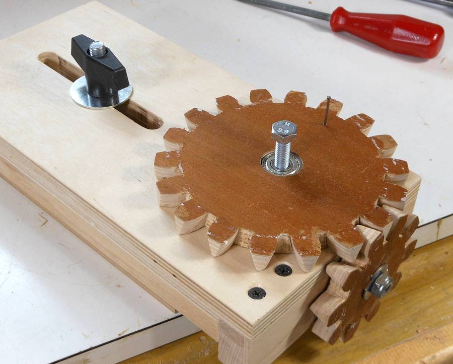 A ball bearing goes in the larger gear. The ball bearing isn't really necessary,
but roller skate bearings are cheap, so might as well use an extra one.
A ball bearing goes in the larger gear. The ball bearing isn't really necessary,
but roller skate bearings are cheap, so might as well use an extra one.
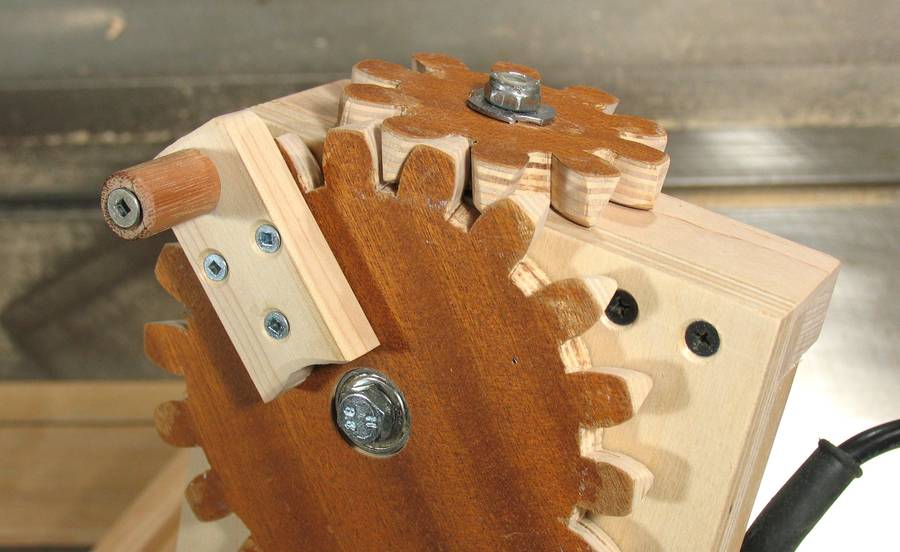 The gearing, finished and with a crank attached.
Some varnish on the gear and gear teeth help them slip against each other.
Varnish on the back of the large gear also helps it slip smoothly against the wood.
The gearing, finished and with a crank attached.
Some varnish on the gear and gear teeth help them slip against each other.
Varnish on the back of the large gear also helps it slip smoothly against the wood.
The varnish should also help resist wear, though after two years, I have so far seen no signs of wear on the gears of my other router lift.
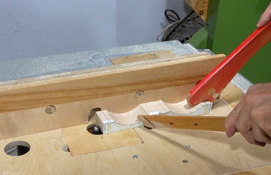
 I cut out the router mounts using templates from the CAD model.
On my previous router lift, I cut that curve using a
table saw cove cutting technique, but
making the mount in two parts on the bandsaw is much easier.
I cut out the router mounts using templates from the CAD model.
On my previous router lift, I cut that curve using a
table saw cove cutting technique, but
making the mount in two parts on the bandsaw is much easier.
 The two pieces for holding the router are still in one part as I route a flat groove in the
bottom. It's easier to do that with the two parts still attached together -
it's a larger work piece.
The hose clamp holding the router will pass through this groove.
The two pieces for holding the router are still in one part as I route a flat groove in the
bottom. It's easier to do that with the two parts still attached together -
it's a larger work piece.
The hose clamp holding the router will pass through this groove.
Ironically, I'm using my other router lift to make this cut. You could mount a router to the bottom of a piece of plywood, or just make a series of cuts with the table saw to cut this slot.
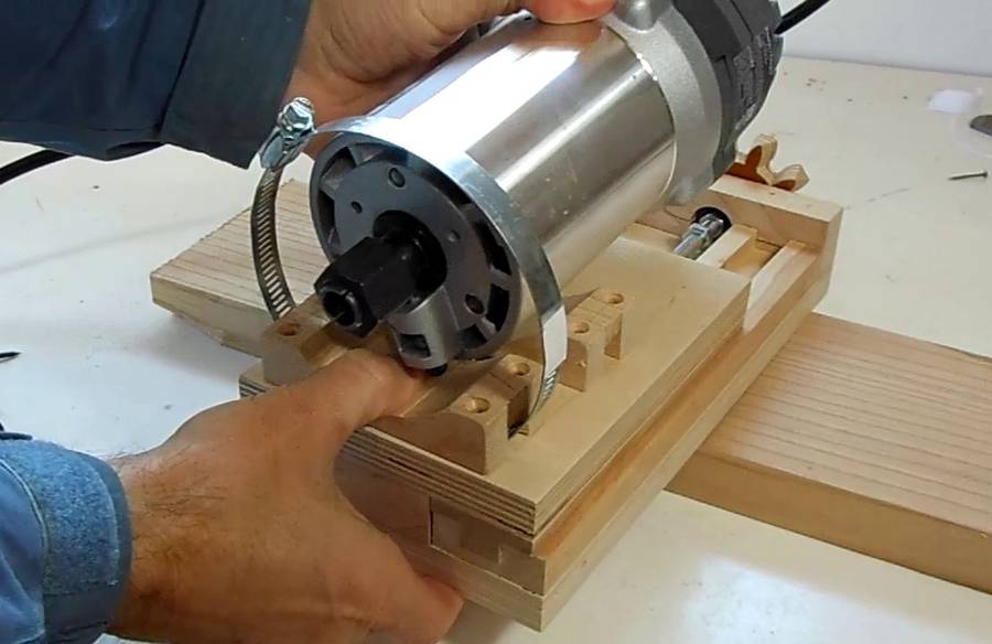 Here's how the router fits with the hose clamps.
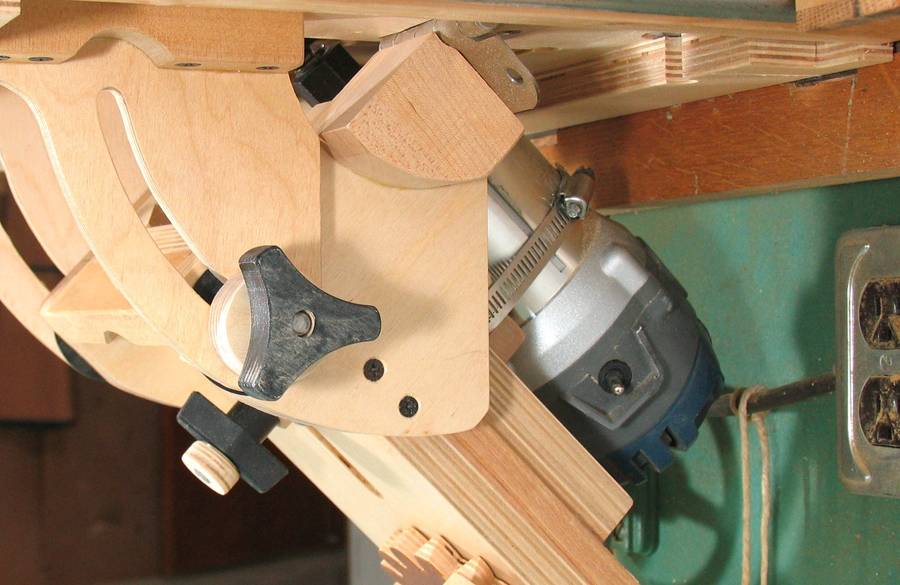 Some people prefer to build a wooden bracket to hold the router instead
of hose clamps. But because I wanted to keep this router lift fairly compact,
space around the router is fairly limited,
especially as the router is tilted 45 degrees. This is the third time
I'm mounting a router with just hose clamps - the mount on my
slot mortiser and on
my previous router lift have not given me any problems.
Some people prefer to build a wooden bracket to hold the router instead
of hose clamps. But because I wanted to keep this router lift fairly compact,
space around the router is fairly limited,
especially as the router is tilted 45 degrees. This is the third time
I'm mounting a router with just hose clamps - the mount on my
slot mortiser and on
my previous router lift have not given me any problems.
Next: Tilting mount, table, and fence