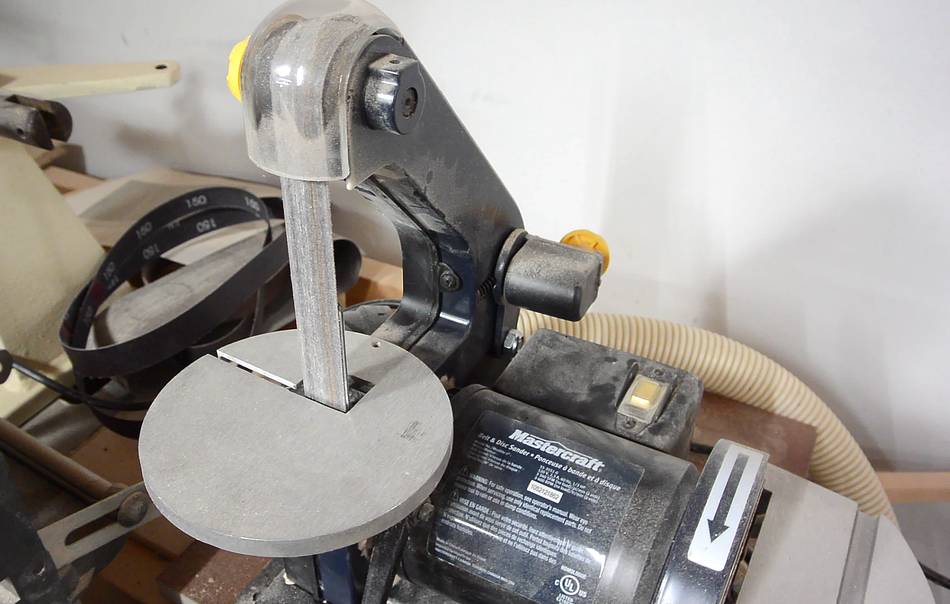
I bought this 1"x30" strip sander at at Canadian Tire a few years ago, and it's
quite handy.
but ther are a few things about it that I don't like. When sanding larger workpieces,
I often hit the back of the sander. Also, I can never seem to get the belt to track on
the center of the platen, and it runs too fast. So I thought I'd try to build a better one.
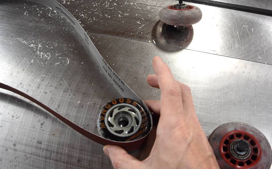
What got me started was a successful experiment at flattening the outside of an inline
roller skate wheel on the table saw. Flattened, they could be the wheels for
a strip sander. I figured this would be a quickie project.
But then I started thinking about various aspects of the design - how to adjust tracking,
how to adjust tension, etc.
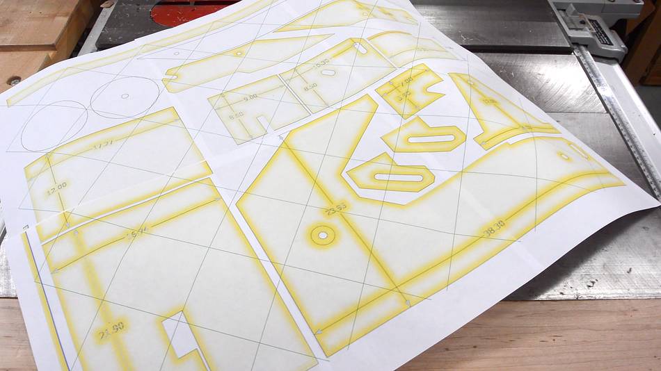
To work it out, I drew a rough CAD model, which then became increasingly detailed.
I then printed out the parts 1:1 for cutting out on the bandsaw
from the cad model using my
BigPrint program.
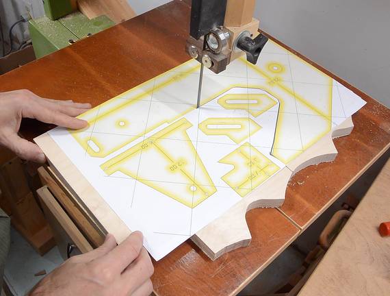
I have to say, even if I had a CNC machine, I'd still cut them on
the bandsaw. I can make better use of existing scrap, put the parts closer
together, and the bandsaw literally cuts 18 mm plywood ten times faster than
a hobby CNC machine would.
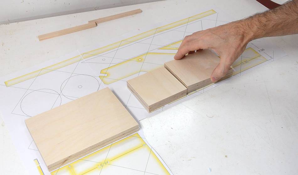
I cut the rectangular parts on the table saw without gluing on the templates.
For simple rectangular parts, it's easier to transfer the measurements than
to glue on a template and peeling it off later.
I checked that I have the right parts of the right size by laying them on the template.
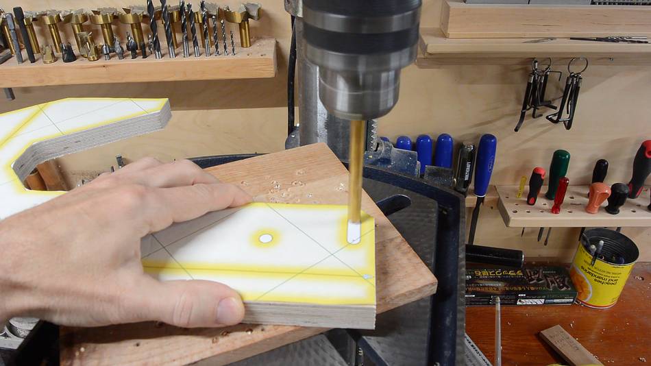
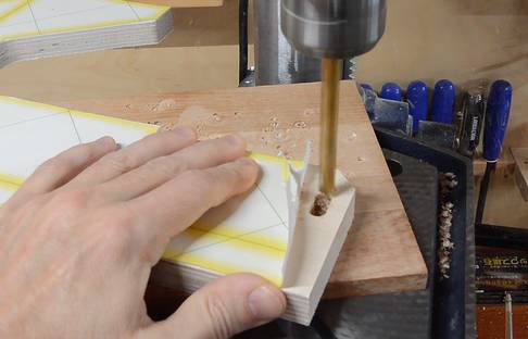
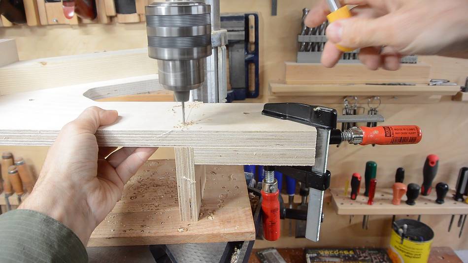
There are a few slots that need to be cut. I cut these by making a series of holes
with a brad point bit, then drilling between the holes. You could also use
a scroll saw. jig saw — or a slot mortiser for these.
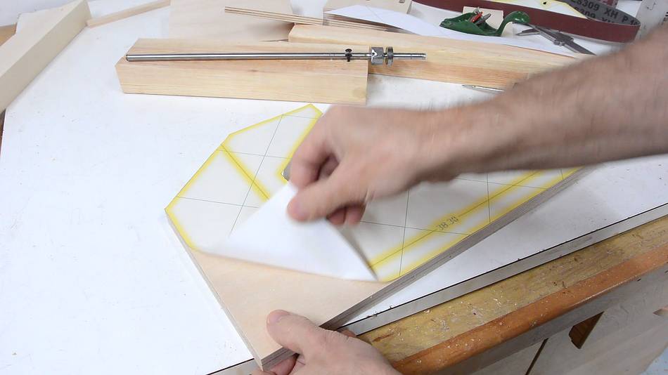
Peeling off the template after cutting. It's only attached with glue stick, so it
comes off easily.
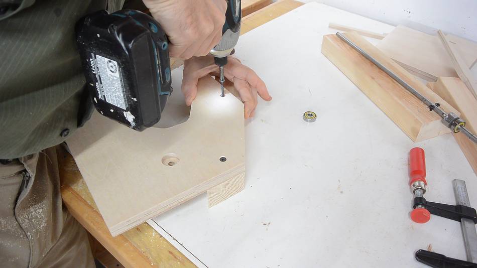
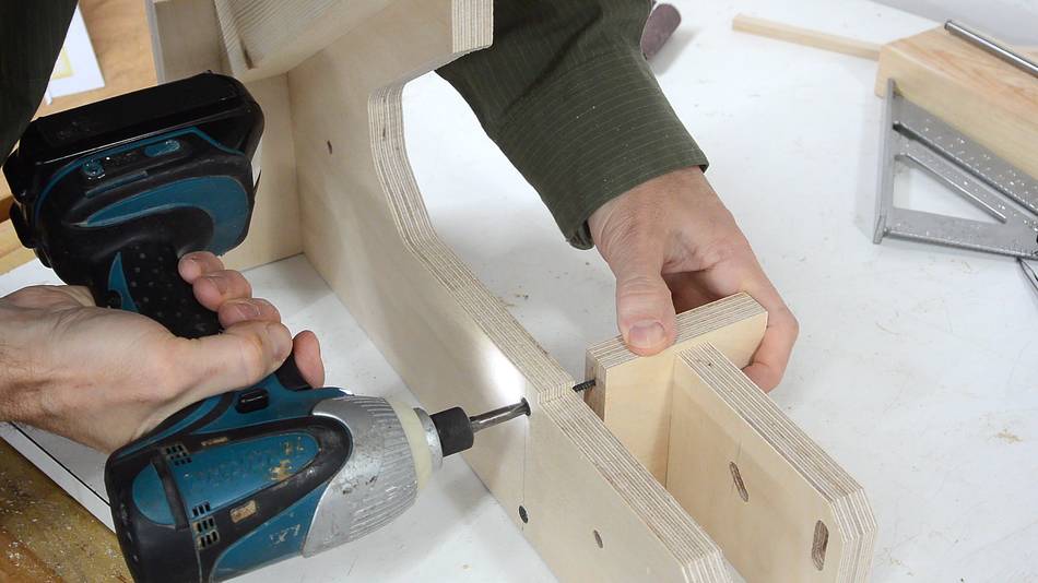
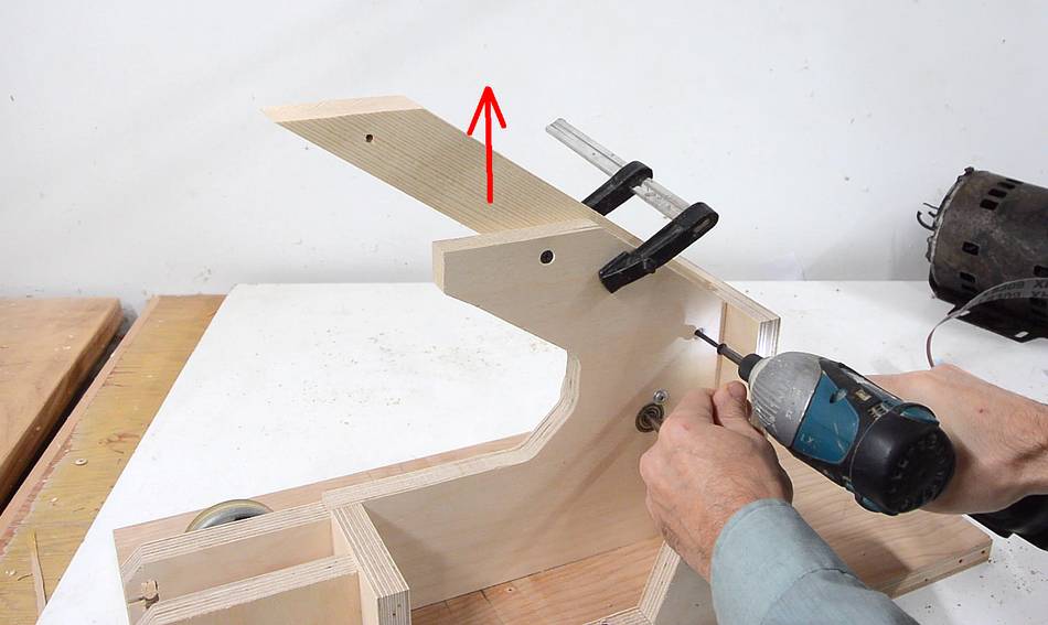
Getting ready to attach the arm that holds the top wheel.
I clamped it in place, then drilled the pilot hole through both pieces to
get the holes perfectly aligned.
This piece will eventually get glued in place, but for now I'm only screwing it on
in case I need to make changes.
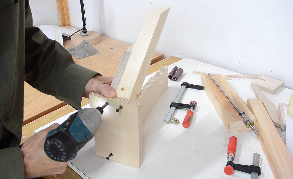
A piece of plywood goes on the back to hold it steady. Aligning that and screwing
through both pieces would have been too difficult, so I accurately laid out the
pattern of holes on both pieces, drilled pilot holes, then used those holes
to align it as I screwed it together.
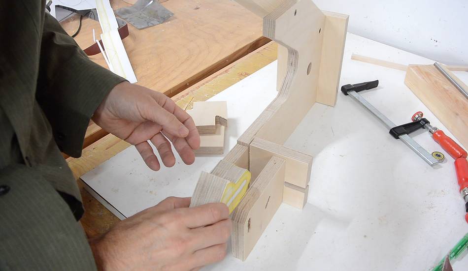
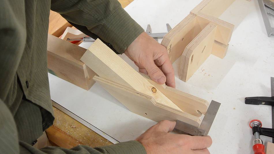
This is how the table support on the front fits together, with just enough
room for the two pieces that I'm holding to fit between two plywood pieces
on the frame.
I used some extra pieces of plywood as spacers to jig things up for where
the holes need to go to leave the two thicknesses of space for the plywood.
I have to say, it's much more evident how I do this in the build video.
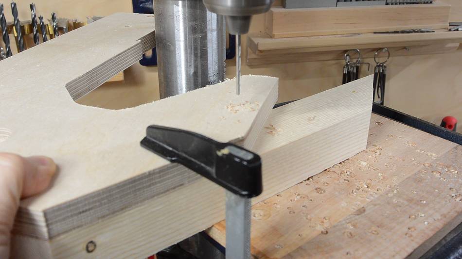
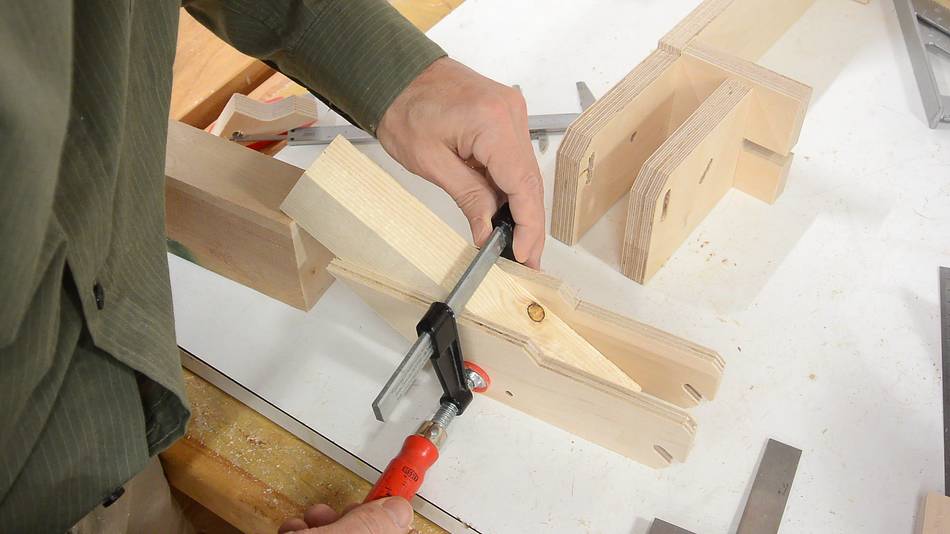
Two parts of the frame need to extend forward by the same amount.
I'm using part of the frame, clamped on to the larger piece
as a spacer to line as I drill the pilot hole for screwing
another piece on. This is more clear in the build video.
After drilling pilot holes, I enlarged the holes in the pieces that
get screwed on so that the screw threads clear the holes.
This helps the screws pull the pieces together.
Upper wheel mount
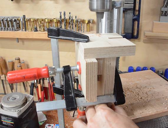
The upper wheel mount is tricky to make because the sides of it need to be precisely aligned
and screwed together.
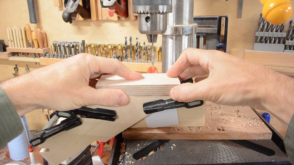
I'm using a scrap that is the same width as the upper wheel mount, plus two pieces of paper
to space them the right distance apart to fit around the wheel mount arm later. I check several
times to make sure these are lined up correctly as I clamp them.
With the two side pieces of the upper wheel mount positioned, I can clamp them together.
Then positioning the upper wheel mount back in place and drilling pilot holes through
it and the sides. I only drill two pilot holes at first.
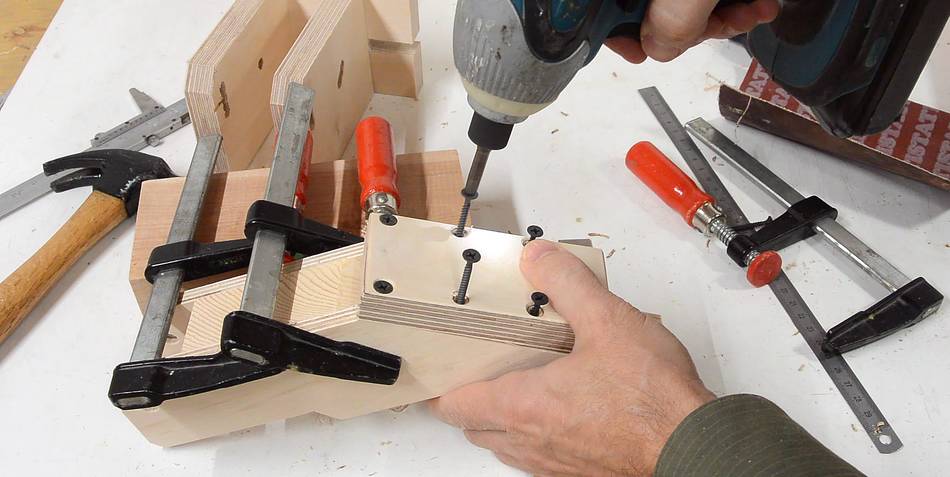
I then put screws in these two pilot holes to keep things aligned.
and drill the rest of the pilot holes
After that I expand the pilot holes in the upper wheel mount back to clear the
screw's threads, and add countersinks for the screw heads.
Then screwing the upper wheel mount back together.
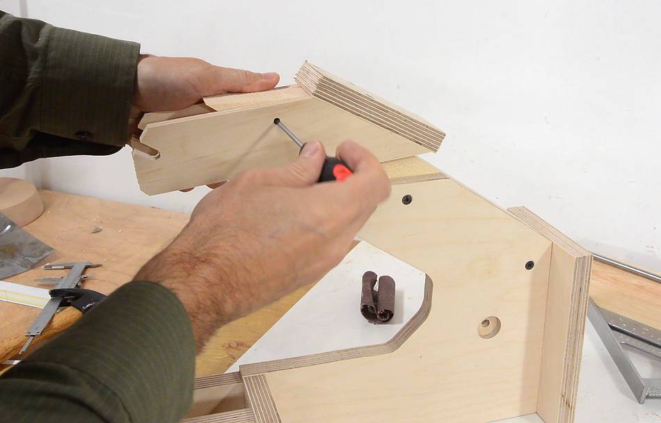
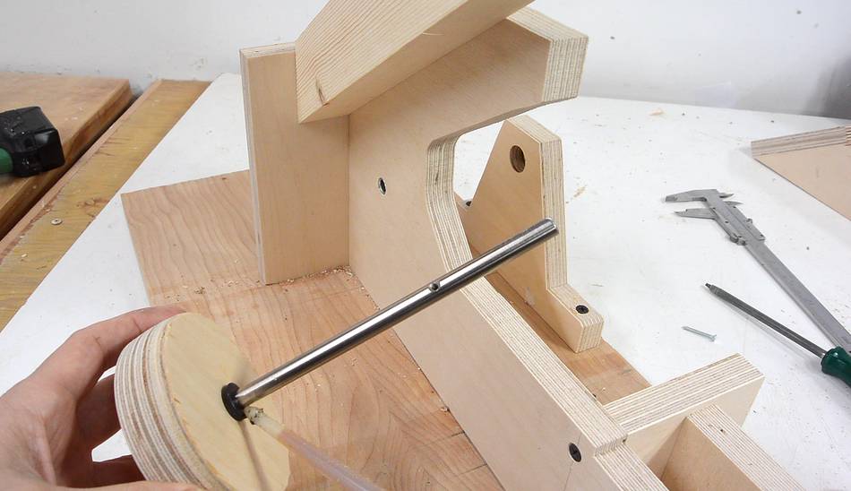
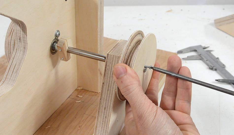
The upper wheel mount pivots on the upper wheel mount arm on a pin.
For the time being, I'm just using a screwdriver to check it.
In the end, I still had to make adjustments to the alignment, using a file
to slightly expand the notch that the shaft for the upper idler rests in.
Idler wheels
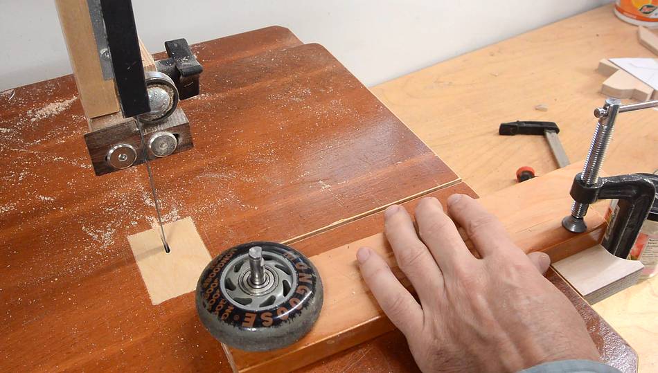
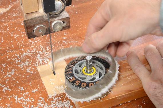
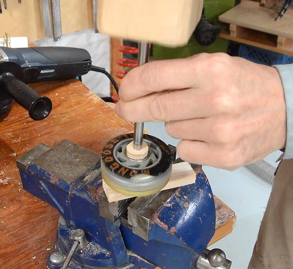
I rigged up a temporary circle cutting jig to cut away the outermost
part of the roller skate wheel on the bandsaw. I could skip this step,
but I'm afraid there might be some sand grains embedded
in the rubber, so I cut away the outer-most layer with a bandsaw.
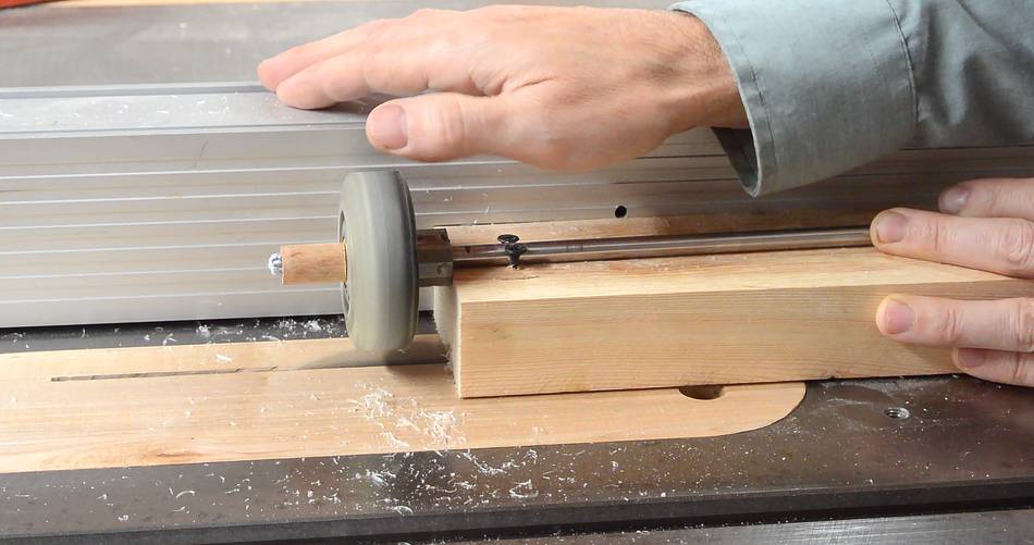
Then spinning the wheel above a spinning table saw blade to shave
it down to exactly cylindrical (I slowly moved the wheel forward
along the blade as I spun it to get a flat cylindrical shape)
After that I shaped a crown onto the wheel buy raising the blade
slightly and pushing the wheel slightly into the blade (not all the way on)
to cut a bevel on one side. After that I flip the wheel around
and cut the bevel on the other side.
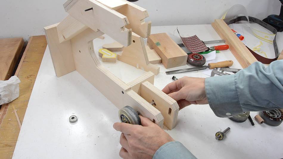
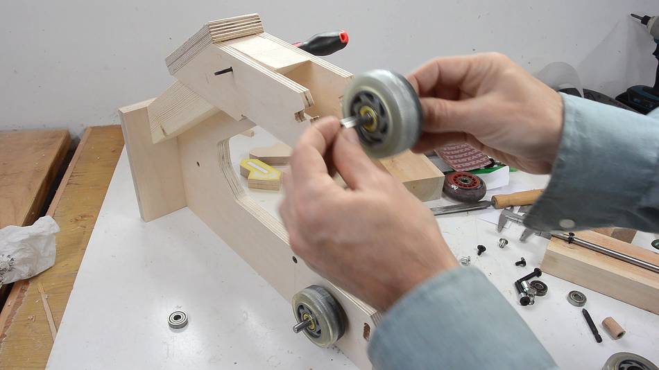
One idler mounts at the bottom...
...the other one the top.
Drive wheel and pulley
The drive wheel needs to be fixed to the drive shaft. It's easier to
make it out of plywood than to adapt a roller skate wheel for the job.
I glued a 18 mm thick piece and a 6 mm thick piece to form a 24 mm thick blank
(ideally, this blank would have been slightly thicker)
I'm using an 8 mm thick shaft for the drive shaft, but you could use a thicker
shaft too, so long as you have bearings that accurately fit the shaft. You
could also use a bronze bushing or a piece of oil soaked maple as a bearing
block for the shaft. Wooden bearings last surprisingly long.
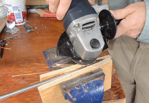
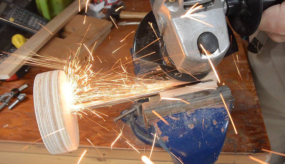
I roughened up one end of this shaft with the coarse wheel on the bench grinder.
I also add a chamfer to the end of the shaft.
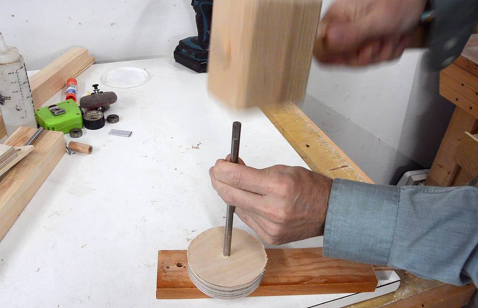
I then pounded the shaft into a hole that is about 1/32 or 0.5 mm smaller than
the shaft. This fixes the wheel on the shaft.
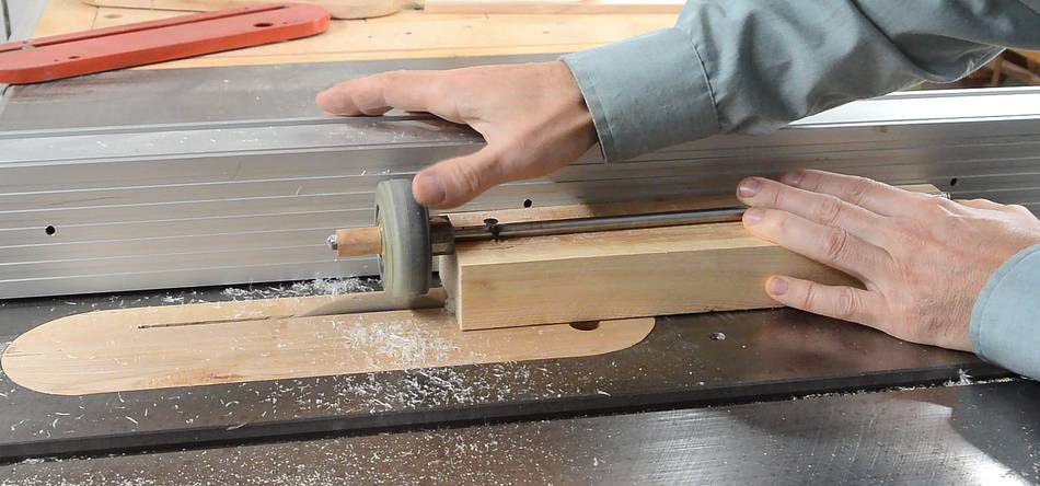
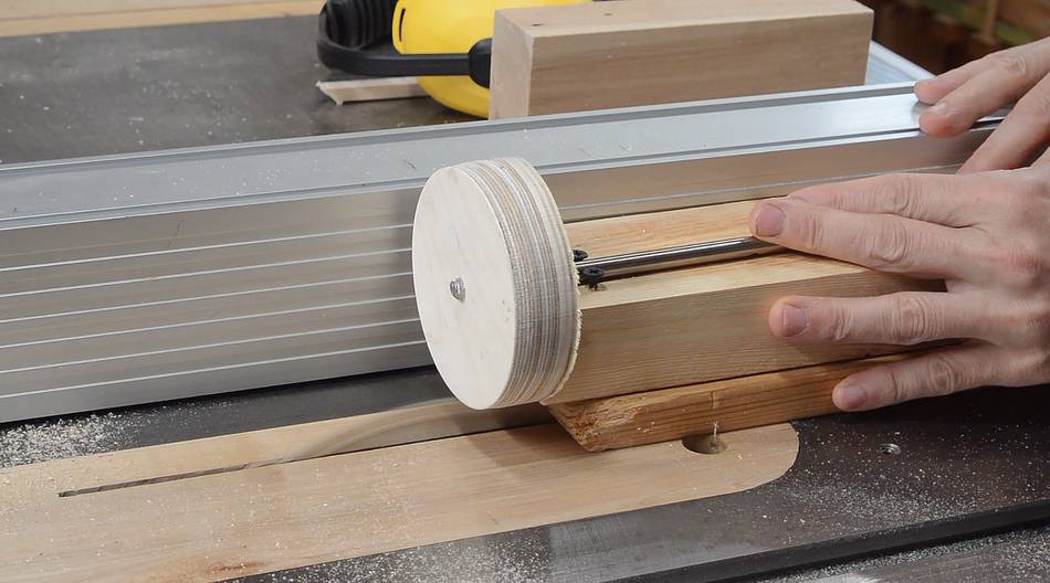
I use the same procedure for rounding the drive wheel on the table saw,
though this time I'm spinning the wheel by the shaft, instead of spinning
the wheel on the shaft.
I used the same procedure to shape a crown onto the drive wheel. But instead
of flipping the wheel over to cut the other side of the crown, I move it
beyond the center of the table saw blade to cut the bevel on the shaft-side
of the drive wheel.
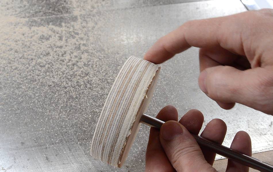
You may be thinking "use a lathe", but it would be very difficult
to mount the wheel sufficiently centered. By spinning the wheel on its own
shaft, I can ensure that the outside of the wheel is exactly concentric
with the shaft. Even if the wheel was mounted with a slight wobble, after trimming
it on the table saw, the edge of the wheel would still be accurate.
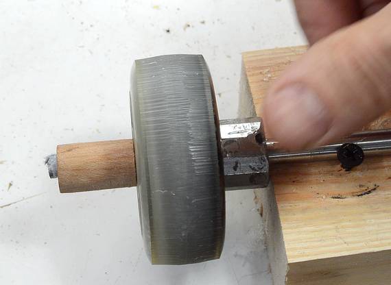
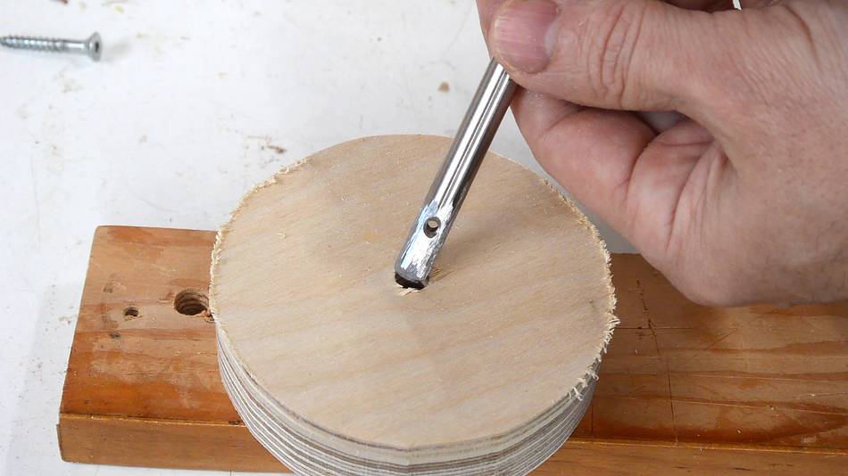
A pulley needs to be attached to the other end of the shaft, and the pulley needs
to be removable so I can put the strip sander together.
I drilled a hole with a tight fit for the shaft, but not so tight that I couldn't
pull the shaft out by hand. I filed a notch in one side of the hole and
ground a groove in the end of another 8 mm diameter shaft with an angle grinder.
With the shaft inserted and the pulley and shaft notches lined up, I drove
a small finishing nail into the space to act as a "key".
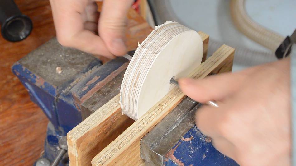
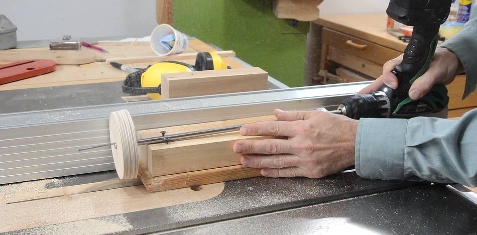
Then cutting the disk that will become the pulley round on the table saw.
Same technique as before, but I'm using a drill to spin the shaft.
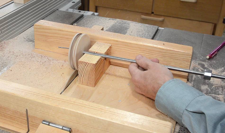
Next I cut the V-belt groove on the table saw. I made a block with a V-notch
to rest on my table saw sled so I could position the pulley precisely without
getting my fingers near the action. This worked well, but I need the
sides of the slots to be angled for the V-belt.
I didn't run into any problems, but let me warn you that this is not a
particularly safe operation. Keep your hands away from the blade. And
be sure to spin the shaft with a drill, not by hand! And use a
table saw sled.
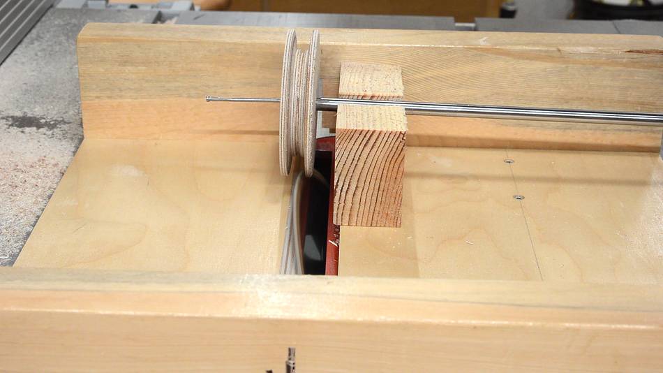
To cut the sloped edges of the pulley, I tilted the blade by 20 degrees and
cut one side of it.
I then put my block and drill on the other side of the blade to cut
the other bevel. I also reversed the drill so I wouldn't be making a
climb cut.
I could have done this by flipping the pulley on the shaft, but moving to the
other side was easier.
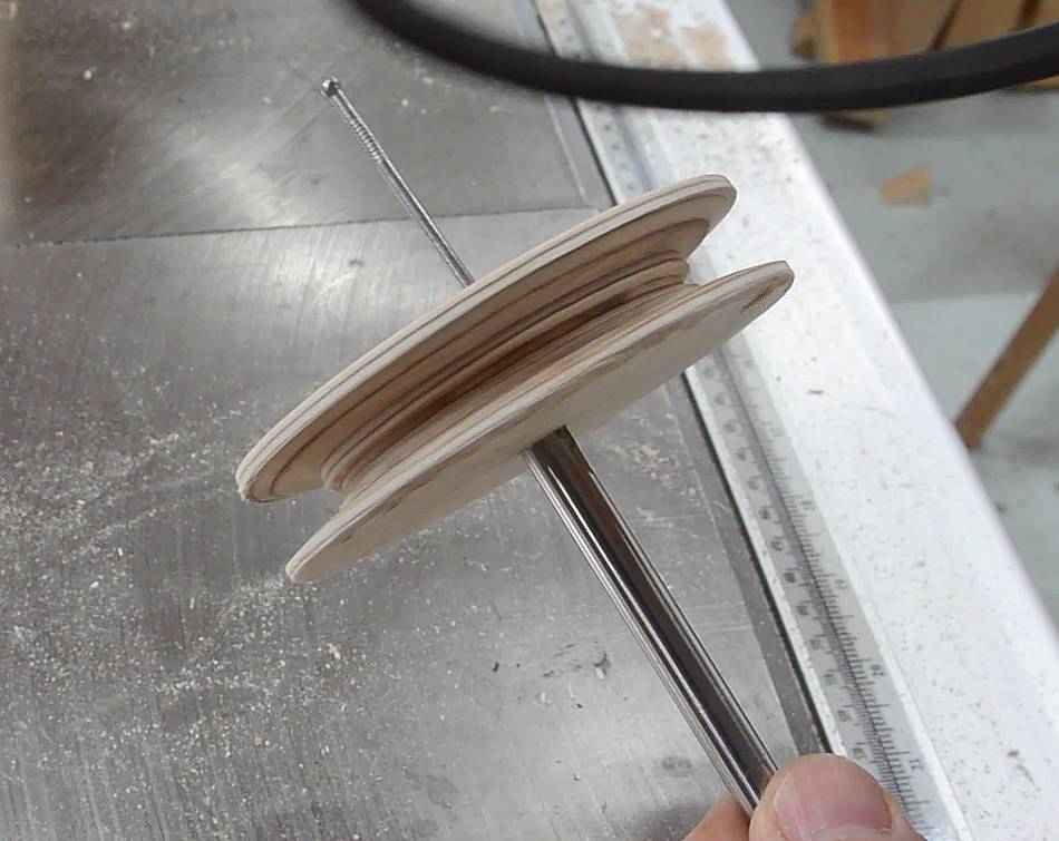
Finished pulley. I cut the initial rectangular slot a bit too wide. But it
looks like this should work. If I run into problems, I can always make another
pulley.
The pulley needs to go on the other end of the shaft that's permanently
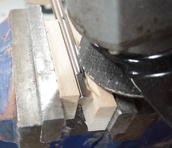
attached to the drive wheel. I cut a keyway into the end of that shaft.
The shaft is clamped between two pieces of hard wood, and I'm actually using
that wood to help guide the angle grinder wheel.
The end of the shaft has a flat spot from its previous application. I cut
that part off later.
Mounting the drive shaft
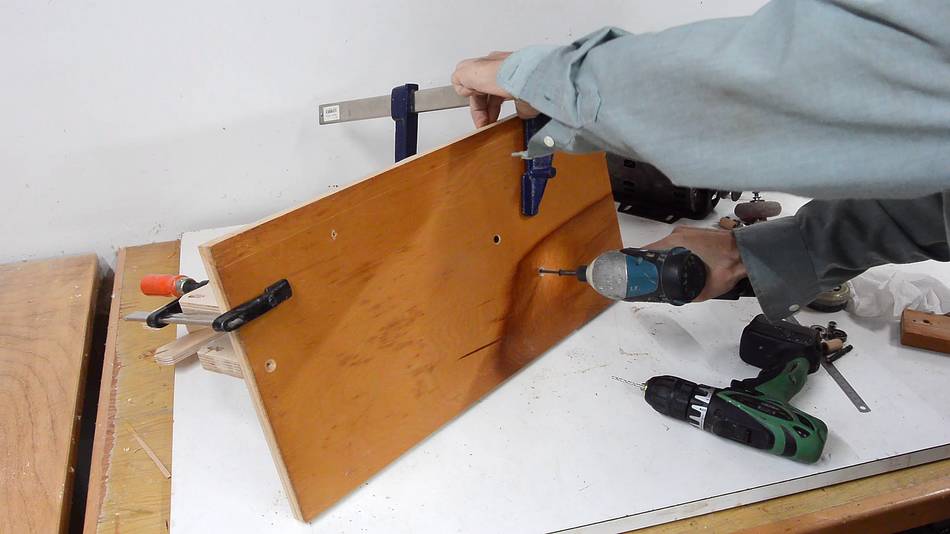
Before mounting the drive shaft, I had to mount the sander frame to the
plywood base. I started by placing it on the base, marking the outline of it,
drilling some holes from the top for where the screws go, and then clamping
the frame onto the base.
I then flipped the base over and drilled pilot holes and screwed the frame
onto the base from below.
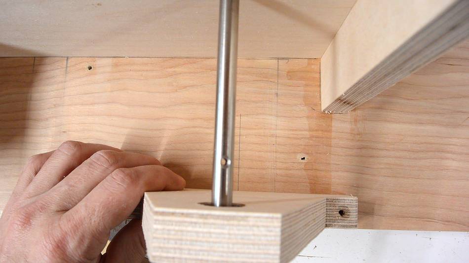
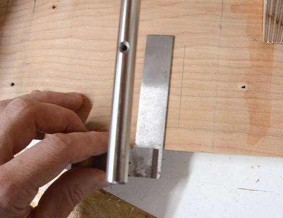
I need to mount the bearing holder for the main drive shaft so that the drive
shaft is perpendicular to the main frame. I drew a pencil line on the base and
positioned the bearing holder to line up the drive shaft by eye.
In retrospect, I guess I could have just held the square against the shaft and
lined it up that way!
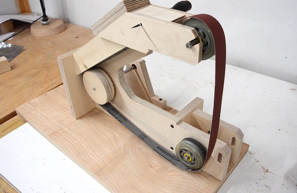
Putting the belt on the sander, Even with it tightened all
the way, there was some slack in the belt. It appears I made the
wheels smaller than anticipated.
I fixed the problem on my sander by unscrewing the top wheel arm, moving it up by
about 6 mm, and screwing it on again.
Some washers behind the drive wheel keep it the right distance from the frame.
I oiled these.
A small spacer bushing and a block of wood clamped to the shaft lock it into
position on the other side.
Also note the bearing, which is barely visible. A screw just above the
bearing keeps it from popping out of the hole.
Now attaching the pulley to the end of the shaft. I used a small #4 screw
as a "key" to make it easier to get it out again if needed.
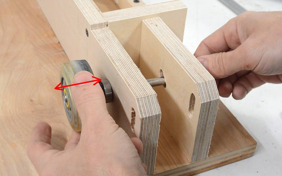
I also need to prevent the lower idler pulley from moving left and right.
I made some spacers out of 1/4" (6 mm) Baltic birch plywood with holes a little
too small, then put one on either side of the pulley (I had to pound the shaft
with a hammer to slide the spacers along). Make sure the pulley isn't squeezed
between the two spacers.
 I bought this 1"x30" strip sander at at Canadian Tire a few years ago, and it's
quite handy.
but ther are a few things about it that I don't like. When sanding larger workpieces,
I often hit the back of the sander. Also, I can never seem to get the belt to track on
the center of the platen, and it runs too fast. So I thought I'd try to build a better one.
I bought this 1"x30" strip sander at at Canadian Tire a few years ago, and it's
quite handy.
but ther are a few things about it that I don't like. When sanding larger workpieces,
I often hit the back of the sander. Also, I can never seem to get the belt to track on
the center of the platen, and it runs too fast. So I thought I'd try to build a better one.