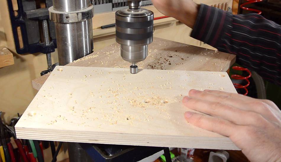
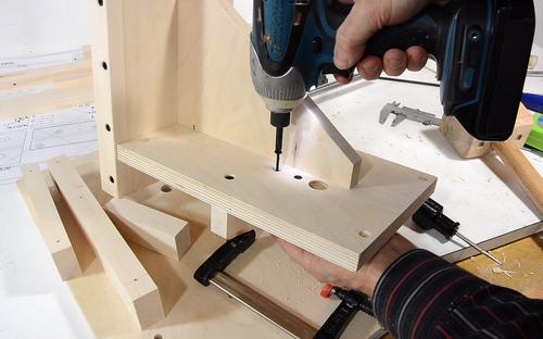
 Next, preparing the plywood pieces for the side-to-side carriage. As before, I
use my paper template to locate the holes, then drill and countersink them
all at once on the drill press.
Next, preparing the plywood pieces for the side-to-side carriage. As before, I
use my paper template to locate the holes, then drill and countersink them
all at once on the drill press.
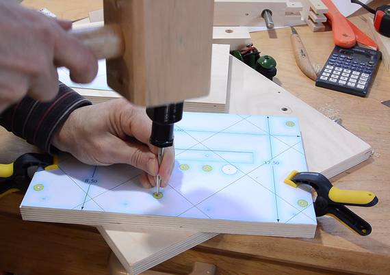
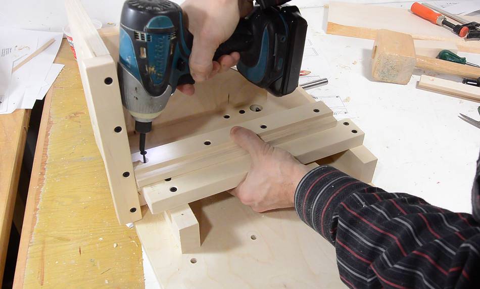
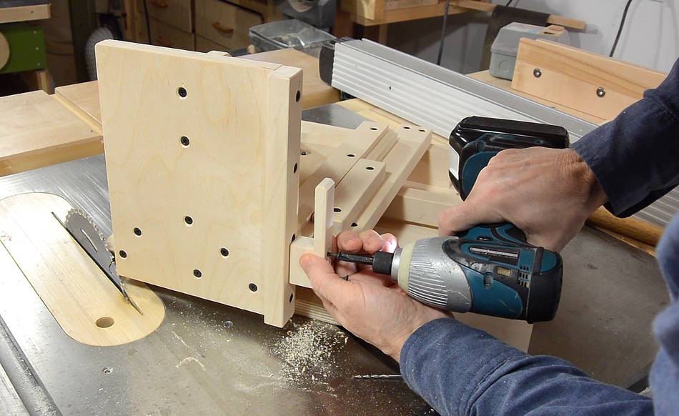
 I use a piece of wood and some clamps to jig the pieces together for
drilling the screw pilot holes all the way through, followed by screwing it
together.
I use a piece of wood and some clamps to jig the pieces together for
drilling the screw pilot holes all the way through, followed by screwing it
together.
 Now attaching a piece of hardwood to act as a fence for the workpiece.
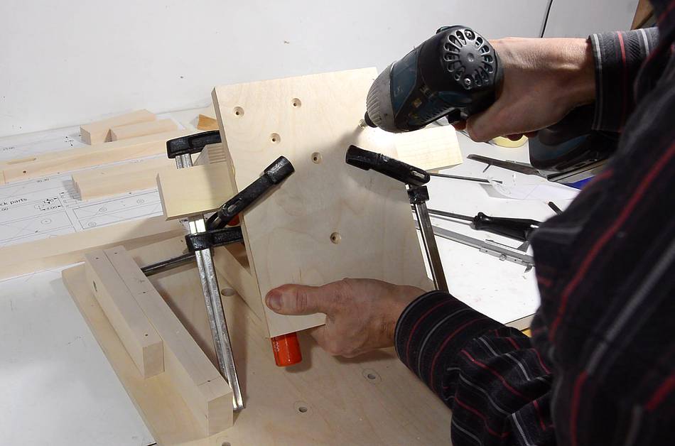
 Attaching the middle of the three pieces that mount the side-to-side
sled on the polished steel rod.
Attaching the middle of the three pieces that mount the side-to-side
sled on the polished steel rod.
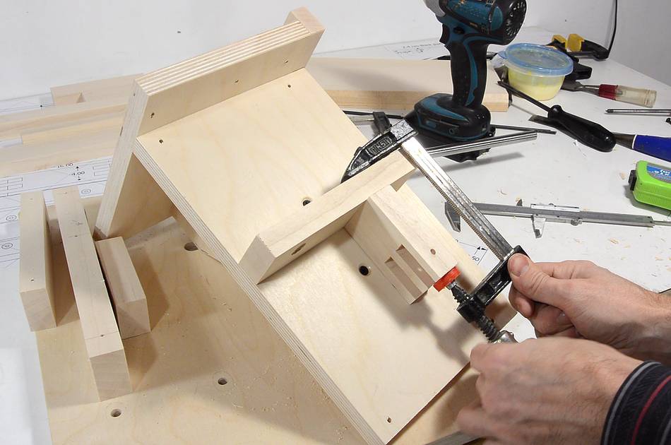
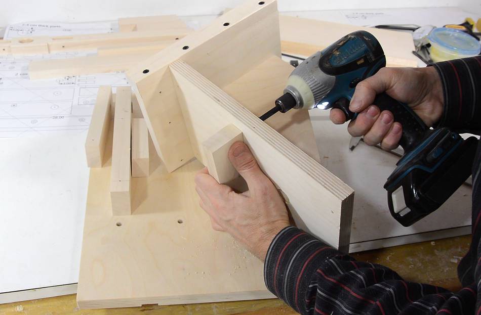
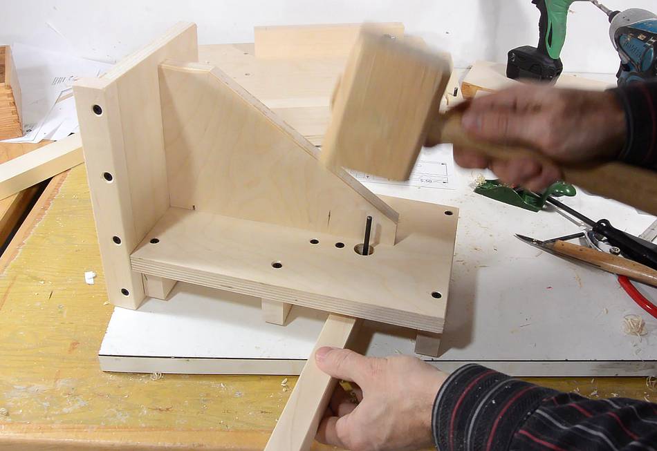
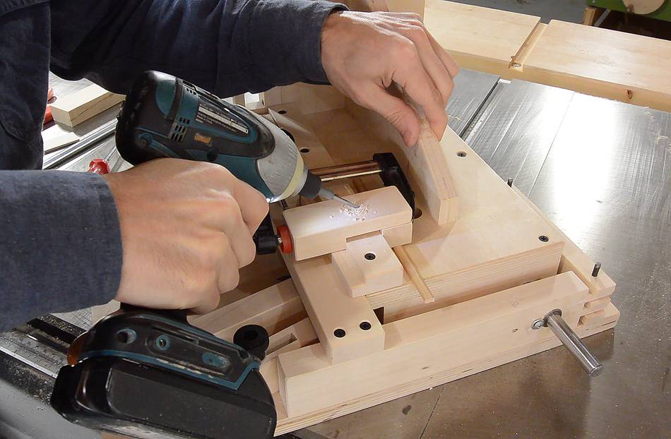
 The E-fulcrum piece butts up against the side of it. Here I clamp it in
place and then screw it on from the top.
The E-fulcrum piece butts up against the side of it. Here I clamp it in
place and then screw it on from the top.
 Another screw, at a slight angle, screws it to the rail on the bottom.
I'm drilling the pilot hole freehand, then adding a screw.
Another screw, at a slight angle, screws it to the rail on the bottom.
I'm drilling the pilot hole freehand, then adding a screw.
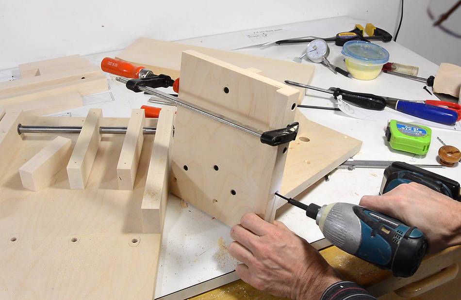
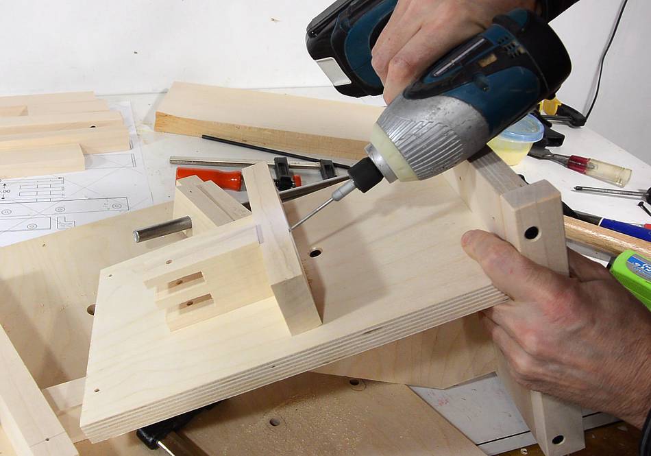
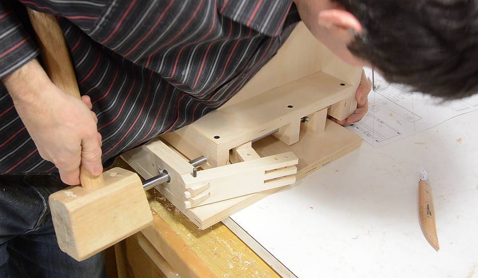
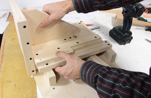
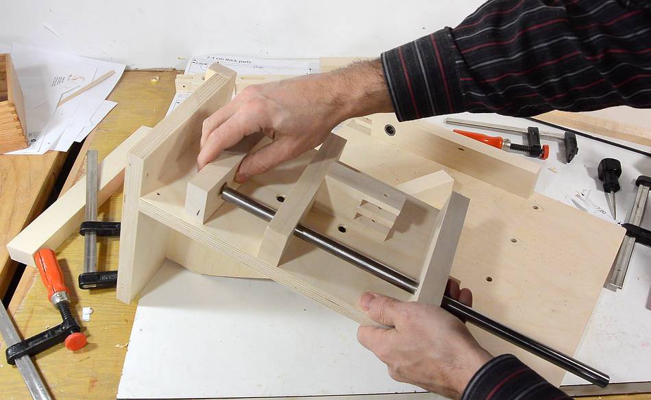 Time to add the remaining two of the three blocks that the shaft goes
through. Here I'm test fitting it to make sure the alignment is good.
Time to add the remaining two of the three blocks that the shaft goes
through. Here I'm test fitting it to make sure the alignment is good.
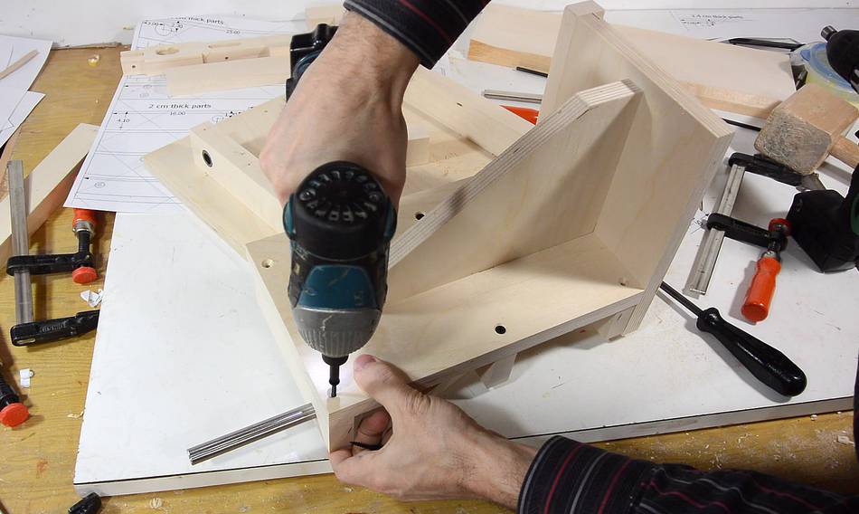 Screwing the other two blocks in place.
With all three blocks screwed on, the shaft is now quite tight. So the alignment wasn't perfect. But on the plus side, I won't have to worry about this shaft coming loose or sliding out.
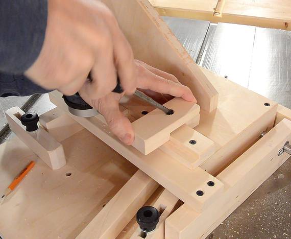
 I mount the lever to the E-fulcrum in the jig.
The hole in the carriage base allows the pin to be inserted from the top.
I mount the lever to the E-fulcrum in the jig.
The hole in the carriage base allows the pin to be inserted from the top.
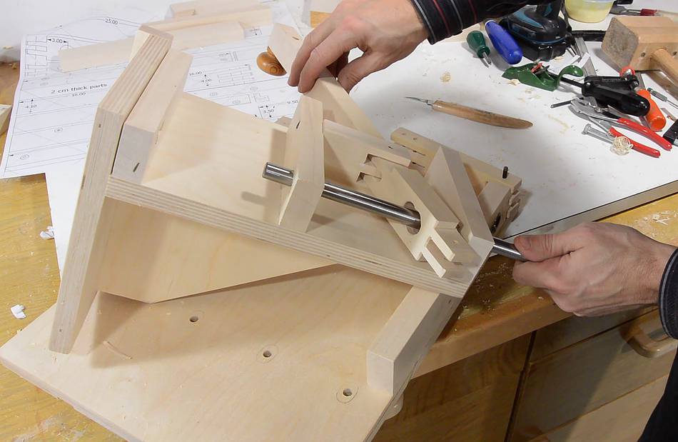 Sliding the shaft part-way in to make sure the lever fits around it.
I ended up chamfering the edges of the hole for the shaft a bit.
Sliding the shaft part-way in to make sure the lever fits around it.
I ended up chamfering the edges of the hole for the shaft a bit.
 After that, I pulled the shaft out again, put the side-to-side carriage
in place, and tapped the steel shaft through all the holes. I ground a
chamfer on the ends of the shaft, which made it easier to get it into all
the holes.
After that, I pulled the shaft out again, put the side-to-side carriage
in place, and tapped the steel shaft through all the holes. I ground a
chamfer on the ends of the shaft, which made it easier to get it into all
the holes.
 The lever now controls the side-to-side motion. But I still need something
to prevent the side-to-side carriage from rotating around the shaft.
The lever now controls the side-to-side motion. But I still need something
to prevent the side-to-side carriage from rotating around the shaft.
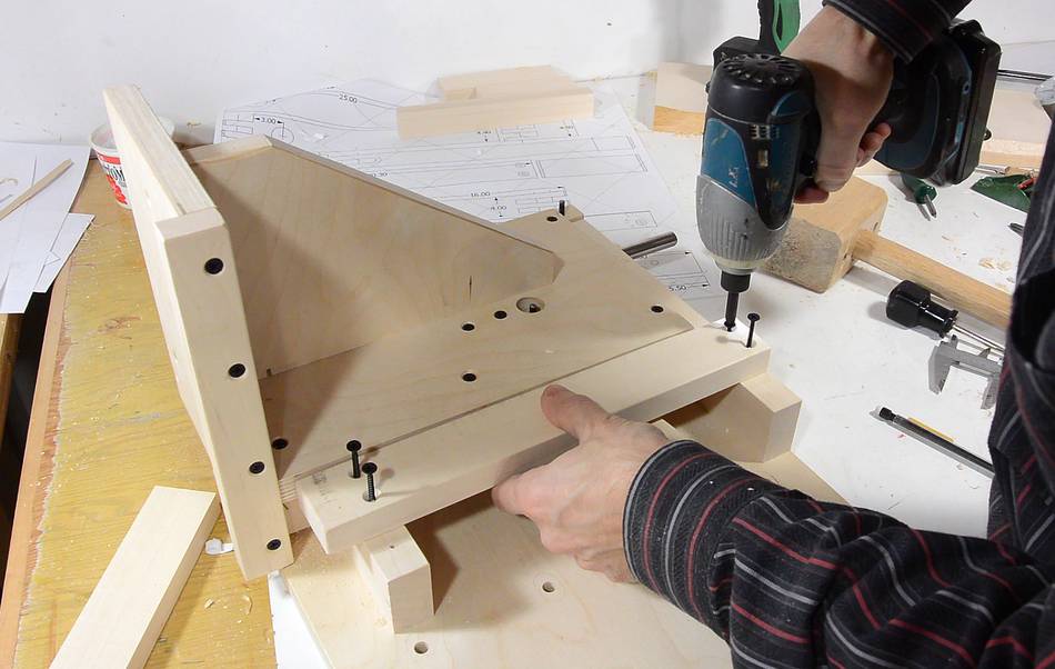 A guide rail the same height as the top of the side-to-side carriage
screws to the front side of the jig.
A guide rail the same height as the top of the side-to-side carriage
screws to the front side of the jig.
 Another rail screws onto the carriage, sticking out forward and over the rail
just screwed on previously. This prevents the side-to-side carriage from
tipping forward.
Another rail screws onto the carriage, sticking out forward and over the rail
just screwed on previously. This prevents the side-to-side carriage from
tipping forward.
 To keep it from tipping backwards, another block is screwed on the front.
This block hooks over the rabbet of the rail attached to the carriage to hold
it down.
To keep it from tipping backwards, another block is screwed on the front.
This block hooks over the rabbet of the rail attached to the carriage to hold
it down.
 I always secure the workpiece to the jig with a clamp. But I'm always
afraid that at some point the clamp might let go and fall onto the blade.
I always secure the workpiece to the jig with a clamp. But I'm always
afraid that at some point the clamp might let go and fall onto the blade.
 So to prevent that sort of accident from happening, the jig has a hook
that the bar of the clamp fits into. So if the clamp should fall, at
least it won't land on the blade.
So to prevent that sort of accident from happening, the jig has a hook
that the bar of the clamp fits into. So if the clamp should fall, at
least it won't land on the blade.
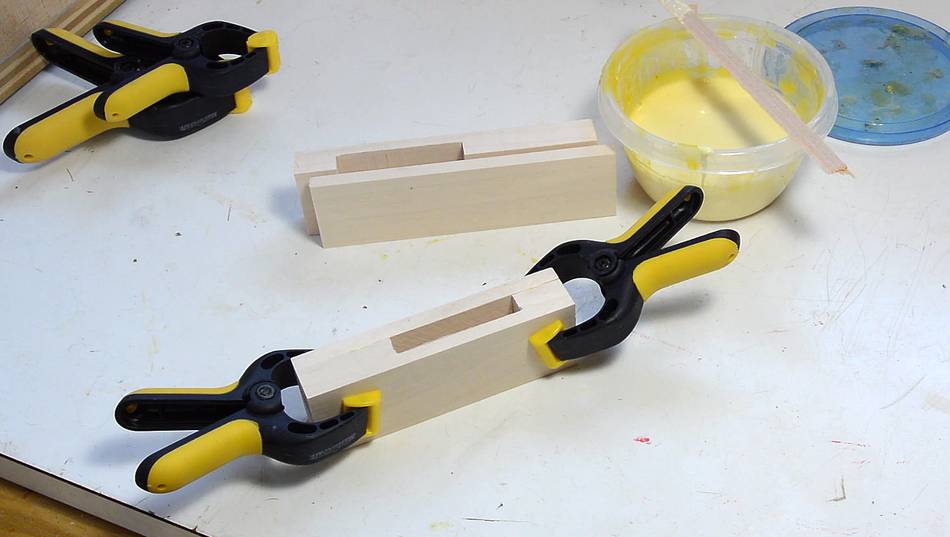
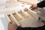
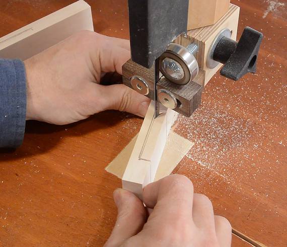 Next making the adjustable stops. These have a slot in them. Last
time I cut these on my slot mortiser. But not everyone has a
slot mortiser. This time I took a shortcut. I just cut the blocks
apart with a thin blade, cut the inside cavity on the bandsaw,
then glued them back together.
Next making the adjustable stops. These have a slot in them. Last
time I cut these on my slot mortiser. But not everyone has a
slot mortiser. This time I took a shortcut. I just cut the blocks
apart with a thin blade, cut the inside cavity on the bandsaw,
then glued them back together.
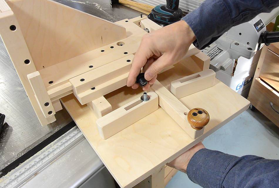 The blocks attach to the base with carriage bolts or T-slot bolts.
Alternately, you could use threaded inserts, or T-nuts inserted into the base from below and make knobs attached to bolts.
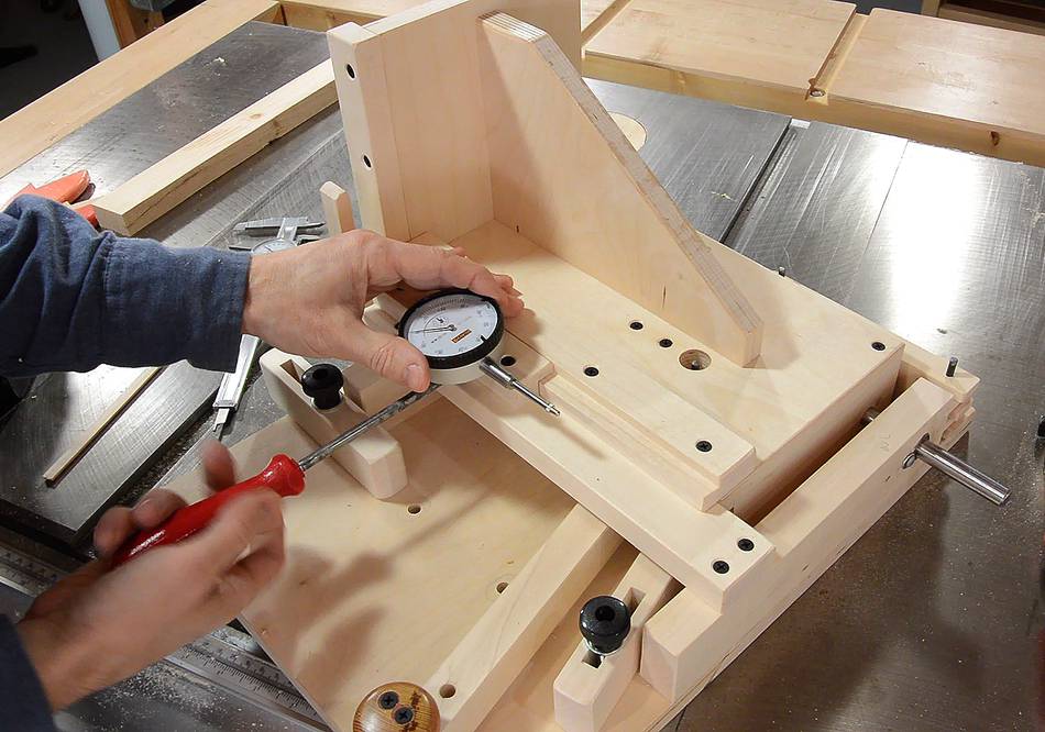
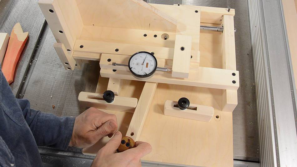
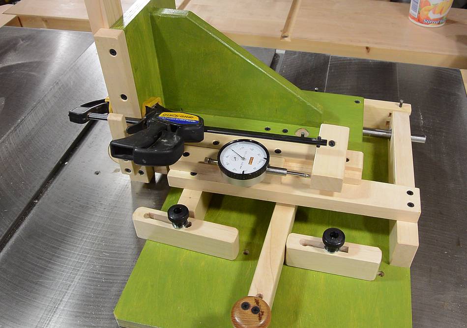
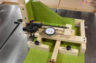
 For set-up and checking, it helps to have some means of
measuring the position.
For set-up and checking, it helps to have some means of
measuring the position.
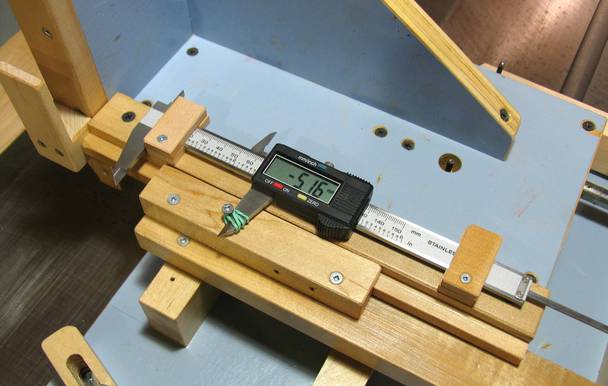
You can use a caliper attached to the sled, as shown at right. A dial caliper would be better, but a dial indicator is better still.
Best to use a dial indicator with a 1" (25 mm) range. The 1/2" ones have too little range.
Even with a 1" range on the dial indicator, it's sometimes not enough, so an adjustable reference point to measure against is needed.
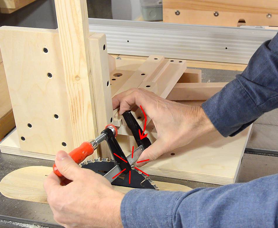
 The reference stop is a sort of "clamp" that attaches to the rail. The clamp
closes by tightening a screw into a block on the far end with a screw at
a 45 degree angle. Getting the holes aligned just right is tricky, so I
clamp the parts in place, then drill the hole through both parts. To
start the hole, I drill about 3 mm in straight down, then tilt the
drill towards me by about 50 degrees and drill the rest of the way.
The reference stop is a sort of "clamp" that attaches to the rail. The clamp
closes by tightening a screw into a block on the far end with a screw at
a 45 degree angle. Getting the holes aligned just right is tricky, so I
clamp the parts in place, then drill the hole through both parts. To
start the hole, I drill about 3 mm in straight down, then tilt the
drill towards me by about 50 degrees and drill the rest of the way.
After drilling the initial hole, I enlarge the hole in the upper part and add a countersink. The clamp is loosened and tightened by turning the screw with a screwdriver.
 Provided that the side-to-side sliding action is smooth and the lever is
fairly stiff, the jig is repeatable to less than .001" (0.025 mm).
Provided that the side-to-side sliding action is smooth and the lever is
fairly stiff, the jig is repeatable to less than .001" (0.025 mm).
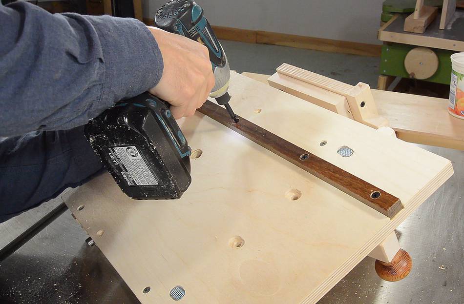 The jig was easier to work with if it's flat on the bottom, so I
saved attaching the bar until now.
The jig was easier to work with if it's flat on the bottom, so I
saved attaching the bar until now.
I made a miter slot bar to go in the slot I cut earlier. More details on making one of these in this article.
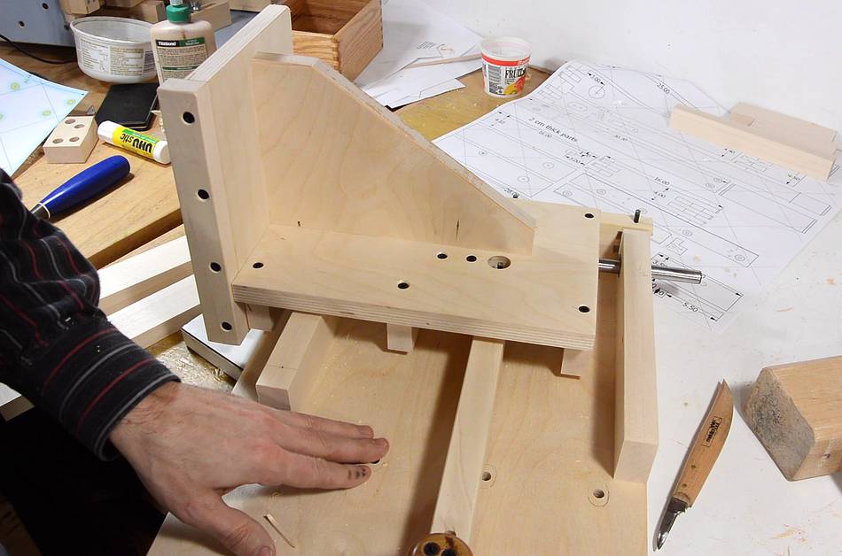
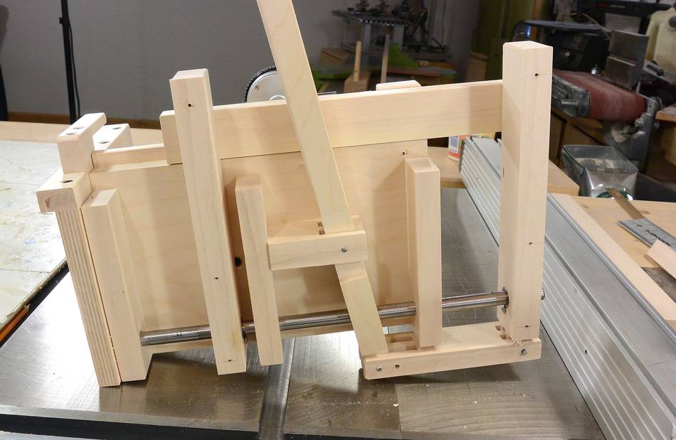 Once the jig was assembled and verified as working, it was time to
take it apart again for varnishing and painting. Here, I've removed
the base. You can see the whole lever mechanism from below.
Once the jig was assembled and verified as working, it was time to
take it apart again for varnishing and painting. Here, I've removed
the base. You can see the whole lever mechanism from below.
 I painted all the plywood the same green that I used for my other
machines - in part, because I still have half a can of that colour.
But the blue-ish gray of my old jig is a nice colour too (and it's
that colour because the recycled plywood I used was already painted)
I painted all the plywood the same green that I used for my other
machines - in part, because I still have half a can of that colour.
But the blue-ish gray of my old jig is a nice colour too (and it's
that colour because the recycled plywood I used was already painted)
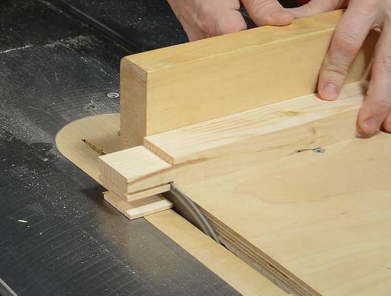
I like to use a quick-grip clamp for holding the stock. The fast one-handed operation makes these clamps ideal for the job.
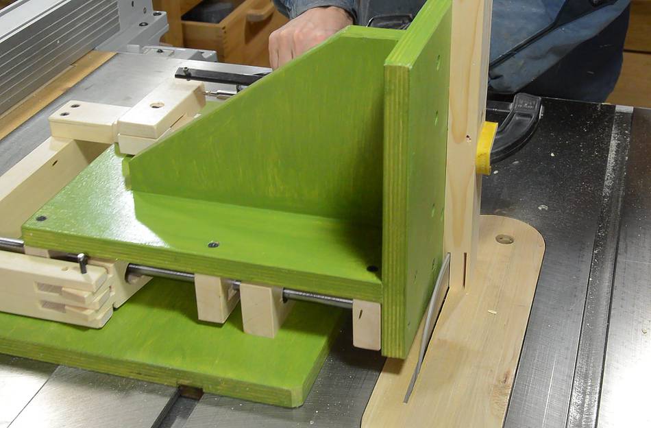 Cutting the tenon.
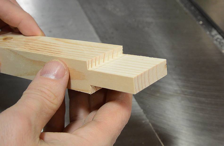
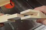
 Unlike my pantorouter,
the cheeks of the tenon still need the shoulders cut in a separate
operation.
Unlike my pantorouter,
the cheeks of the tenon still need the shoulders cut in a separate
operation.
The jig is very fast to operate, but to me, the coolest aspects of it are the fine adjustability and the repeatability of it.
To my woodworking website
 Bridle joint with the
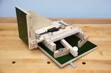 Harlan Opie's quick-set tenon jig
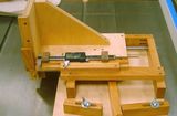 Dan CHernoff's quick-set tenon jig
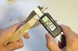 Mortise and tenon joint accuracy
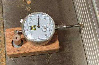 Table saw fence
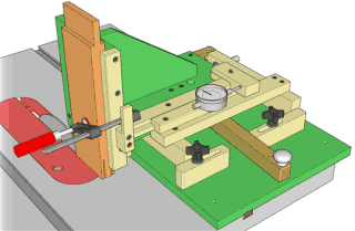 Buy plans for the tenon jig