I wanted to experiment with building a belt grinder. But not having experience with
one, I wasn't sure if it was something I had much use for, so I didn't want to build
a typical belt grinder design such as
Jeremy Schmid's,
John Heisz's,
Cosmas Bauer's, or
this one.
And of course, out of wood, because it's what I know best, and quickest and cheapest.
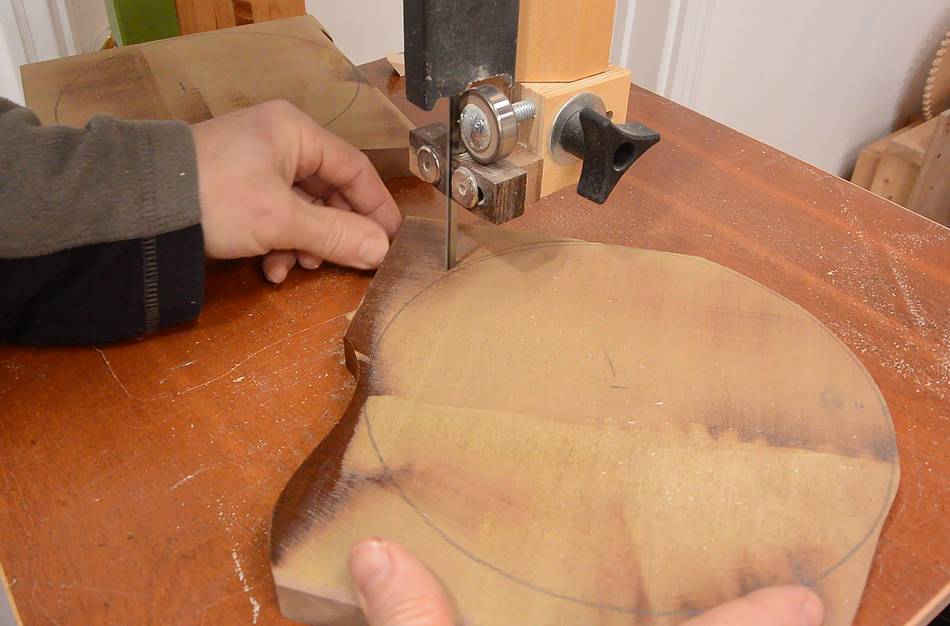
I used some scrap MDF that used to be a headboard to cut some disks to make the main
drive wheel out of.
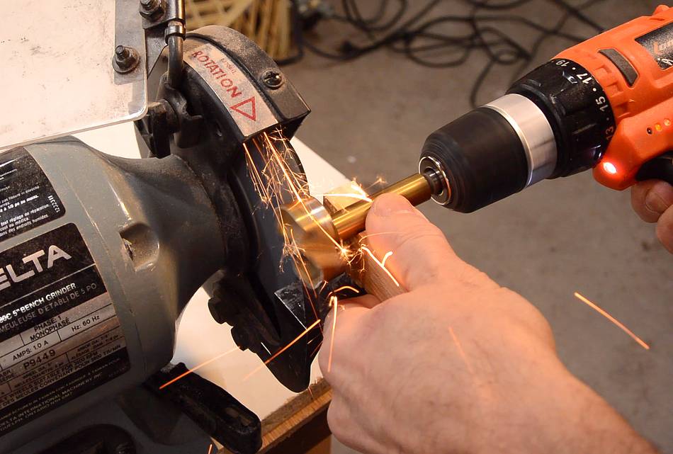
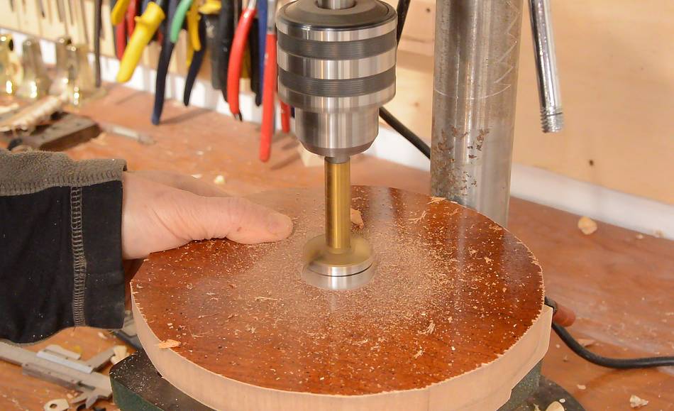
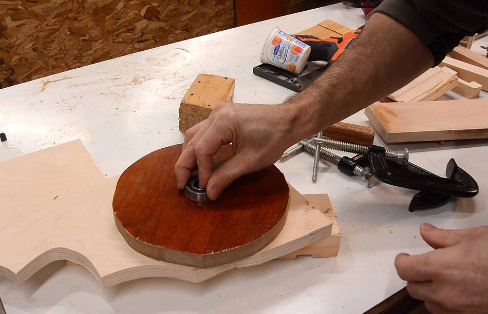
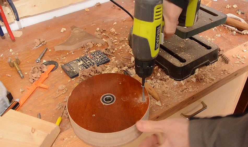
My 3/8" Forstner bit made a hole that fit a 35 mm bearing just snug, but I needed
a press fit. So I ground a slight bit off the outside of the Forstner bit to
make it drill holes that fit tightly.
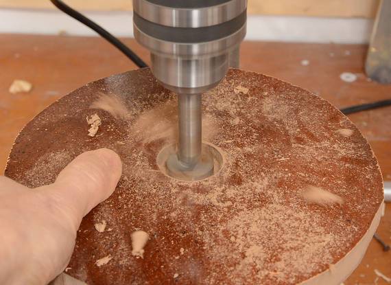
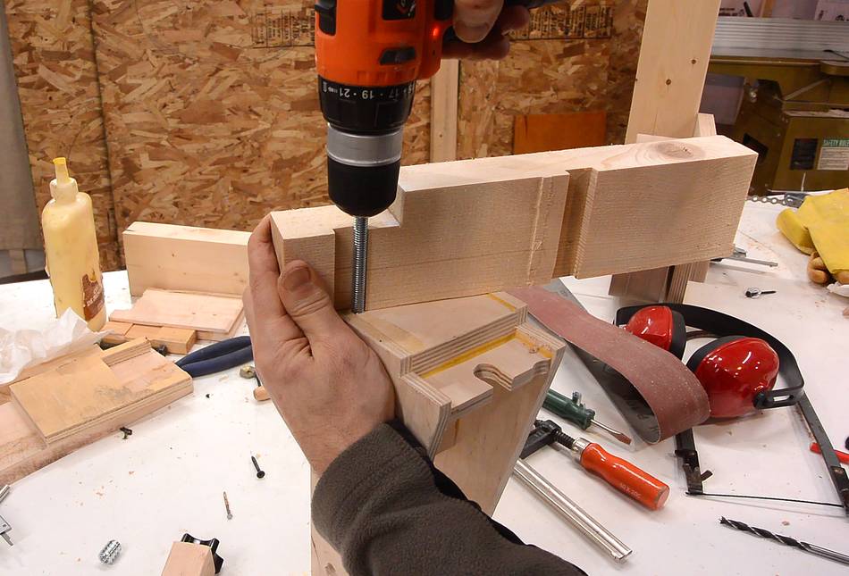
I marked a line on the drill to help guide how deep to drill (the depth stop
on this drill press is missing).
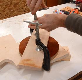
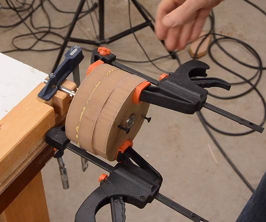
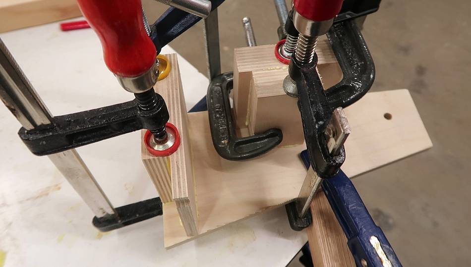
The bearing fit quite tight. I used two C-clamps and a board to press
it in the hole.
For bearings mounted in a wheel, a press fit is essential or the bearing
will work its way loose eventually.
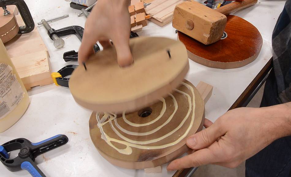
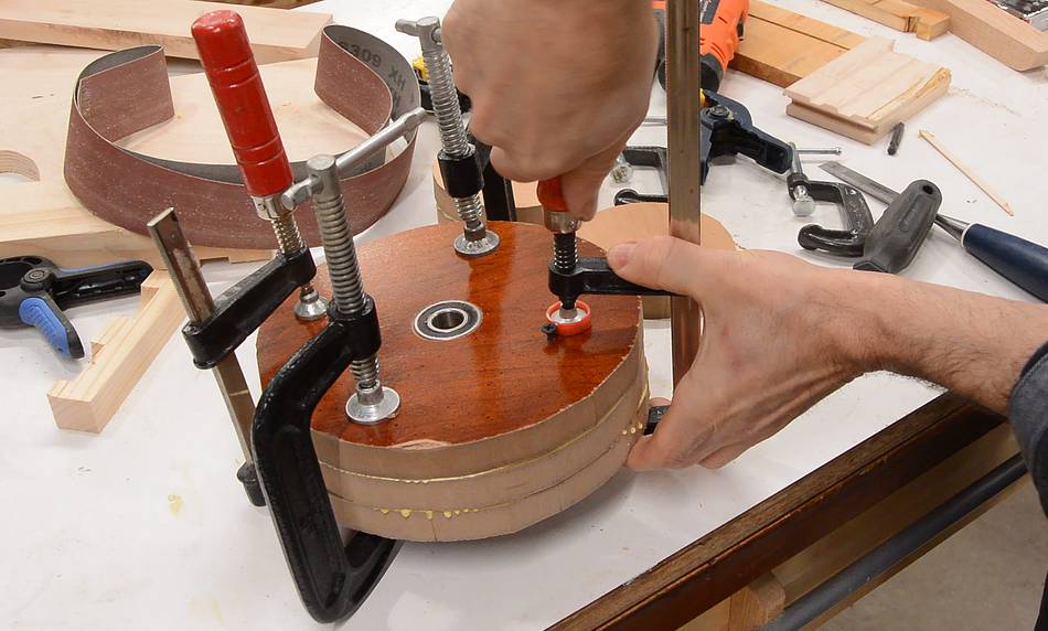
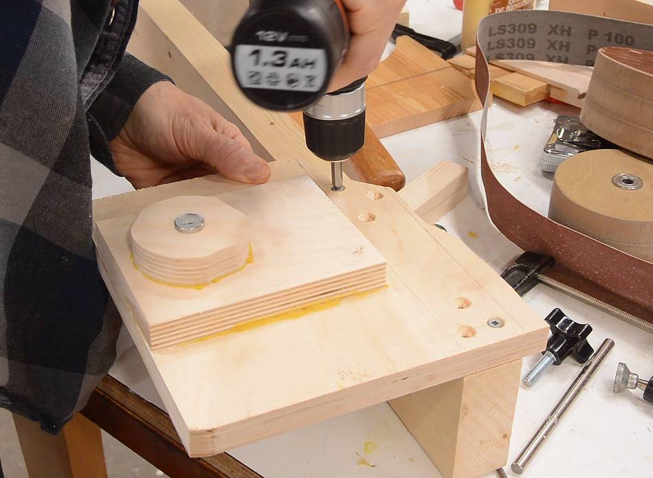
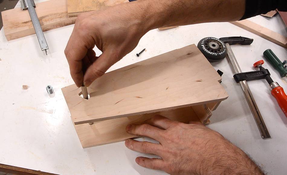
The wheel will consist of three layers. The problem when laminating
layers together is that they float on the glue and get out of alignment
while clamping together. So I drilled two holes to fit screws (just
large enough that I could push the screw through the holes), then
aligned the layers and tapped the screws into the second layer with
a hammer.
The screws then acted as alignment pins while I glued two layers together.
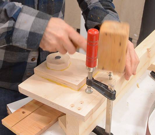
Aligning the third layer (which has the other bearing in it) is more critical.
Any misalignment results in wobble of the wheel.
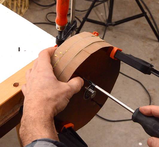
I clamped the third layer on, then carefully aligned it so the wheel did
not wobble, then screwed the screws
further in so they got into the middle layer.
Then gluing the third layer on, same way as the second layer, with the screws as
alignment pins.
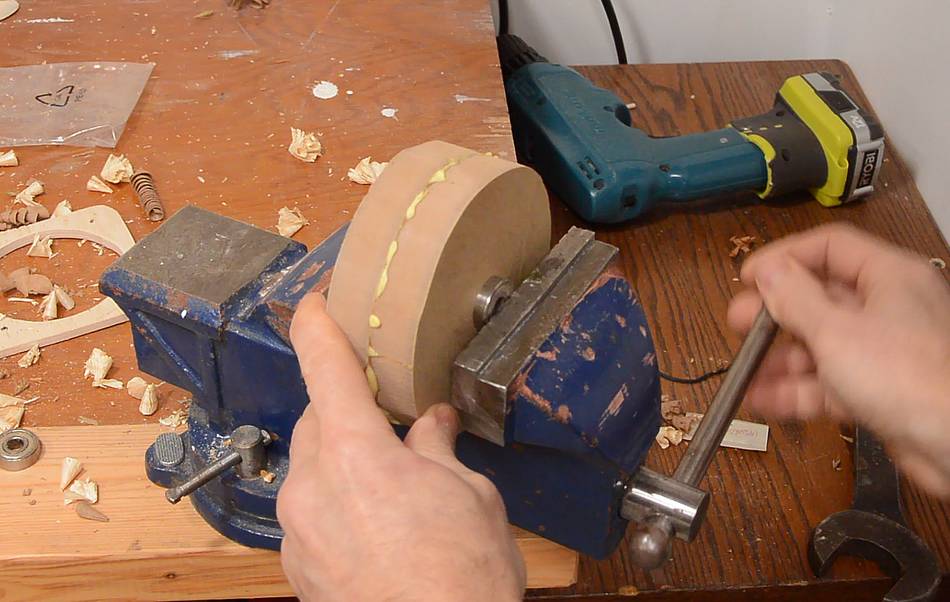
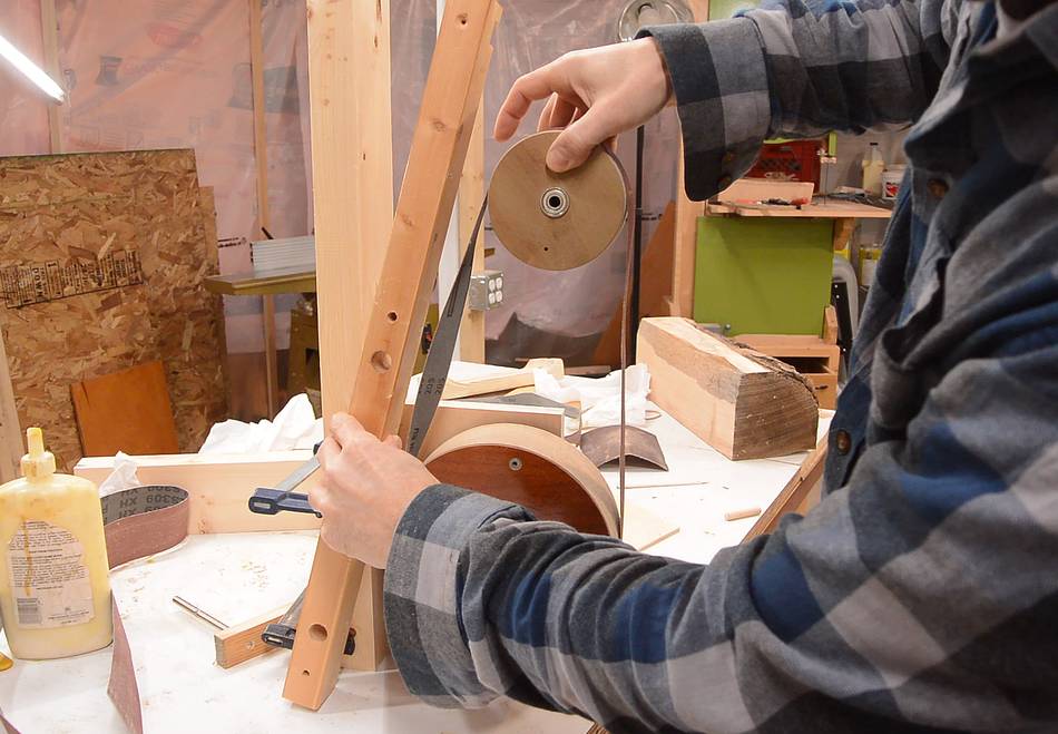
I also made a smaller wheel for the top using the same method. But this
was small enough that I could press the ball bearings (roller skate
bearings) in with a vise.
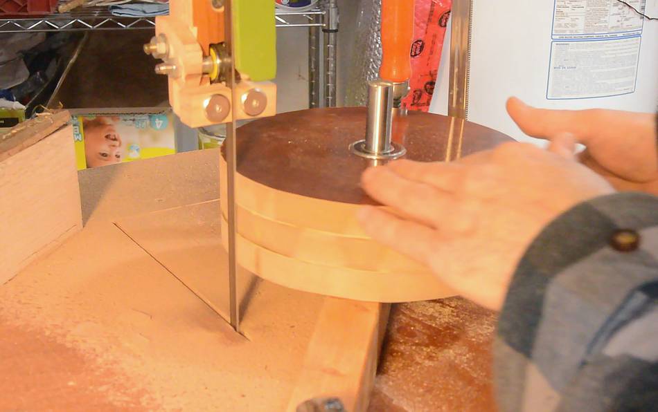
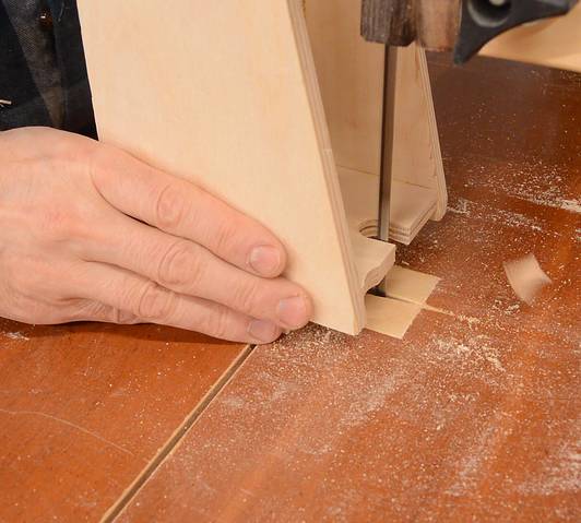
I tried to trim the wheel to perfectly round on the bandsaw, but the blade
wasn't stiff enough. The workpiece just pushed the blade to the side as it cut.
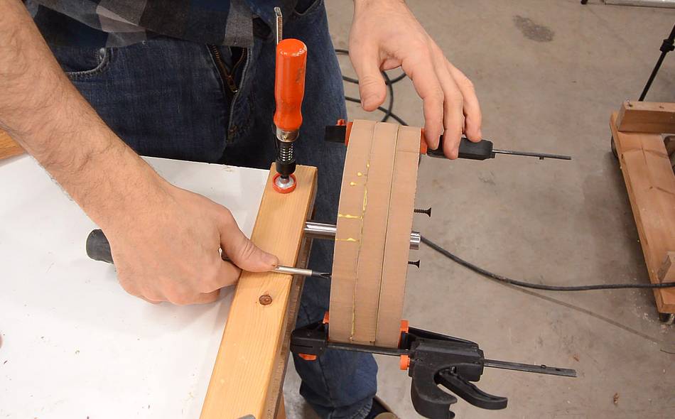
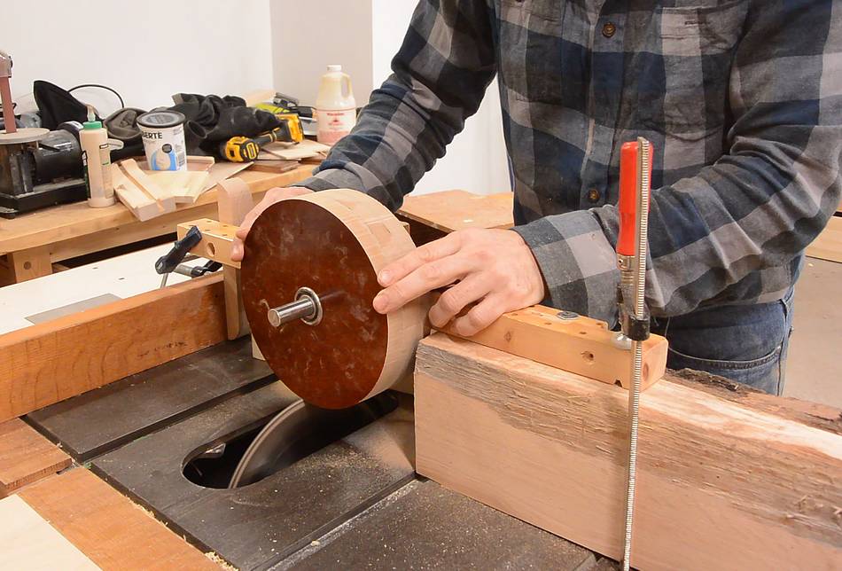
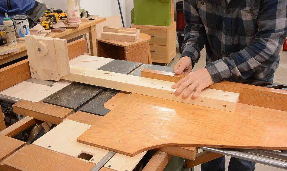
So then I rigged it up on the table saw, which is much stiffer.
I also arranged it so I could push the wheel forward and back along the shaft
so I could cover the cylinder and make sure its surface was perfectly parallel to
the shaft.
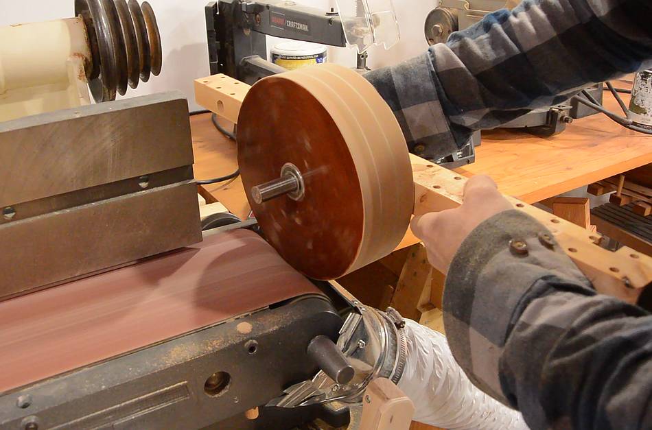
Then adding a chamfer to the edges on the belt sander.
I trimmed the top wheel the same way, but added a slight "crown" to it. Basically,
it's slightly barrel shaped. This helps the belt track on the wheels.
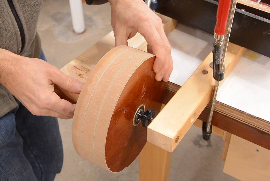
The big wheel was slightly out of balance, but the bearings did not turn freely
enough to balance it just by gravity. Previously I worked around this by
letting it roll on smaller bearings inside the main bearing, but with these
bearings just 16 mm inside diameter, the only bearings I had that were small
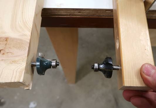
enough were ones for router bits. I was going to put two of these bearings
on a shaft, but then I had the idea of just mounting the router bits,
with bearings in two pieces of wood.
It's probably better to balance the wheel by drilling holes in it, but I didn't
want to have a big hole in the surface, so instead I used two wood screws
to add weight to the light side.
My original idea had been to have the back column of the sander slanted so the
top wheel would be forward enough for the front of the belt to be vertical.
But if I use it with different lengths of belt and moved the top wheel along
the post, the belt wouldn't stay vertical. So I made the column vertical and made
the top wheel holder long enough to bring the front of the top wheel in line with
the bottom wheel.
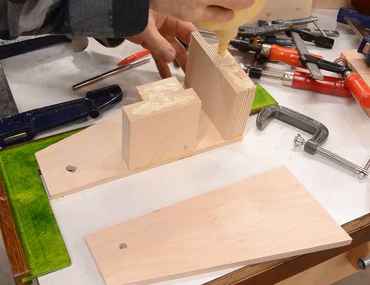
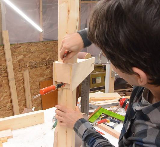
Gluing one side of the top wheel holder together. It's easier to glue in two
stages so there are fewer pieces of wood that need aligning at a time.
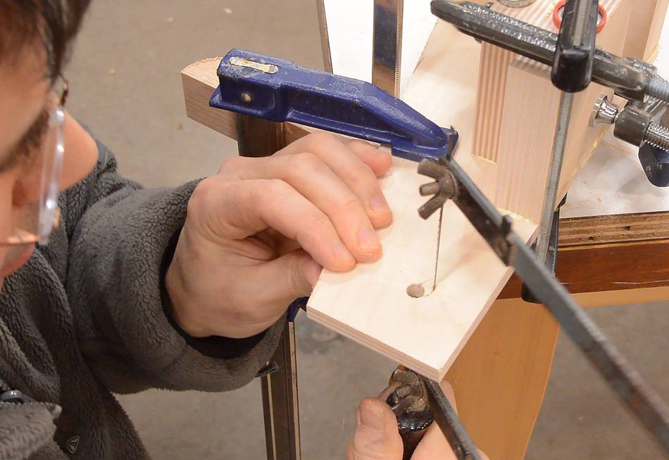
After gluing up the first half, I realized I wanted one hole to be a slot
to allow for adjusting tracking, so I cut that out with a coping saw while
it was clamped up.
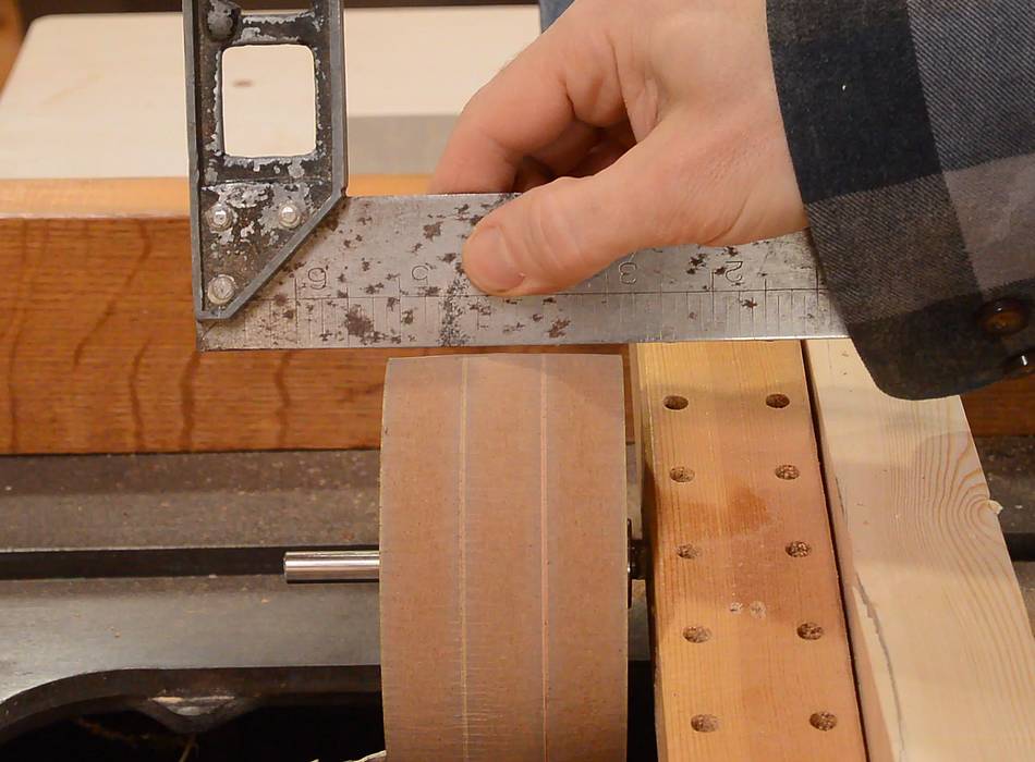
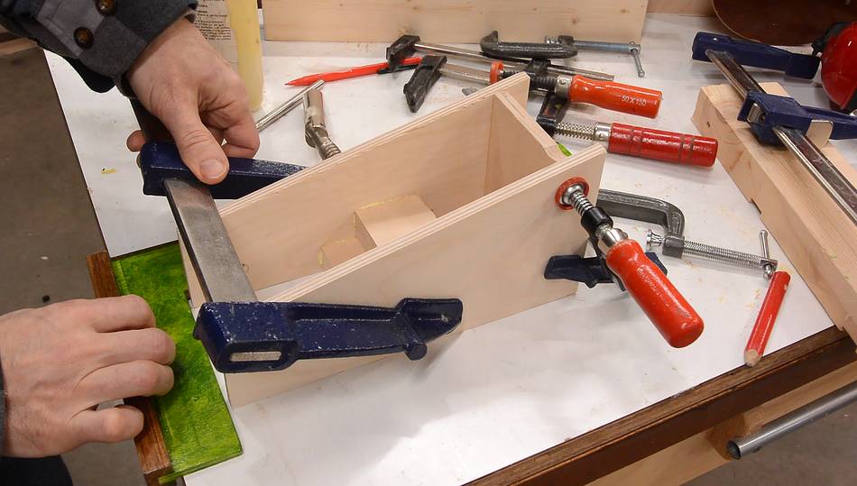
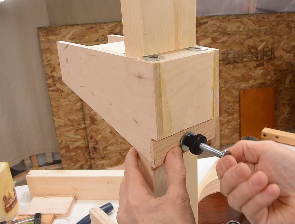
Then gluing on the second layer, relying on my workbench surface and a square
to help keep it aligned as I clamped it.
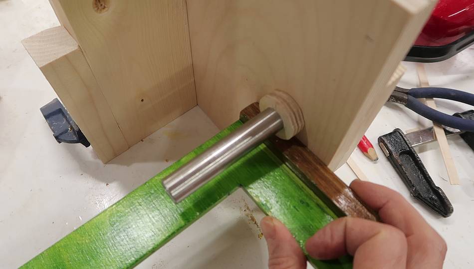
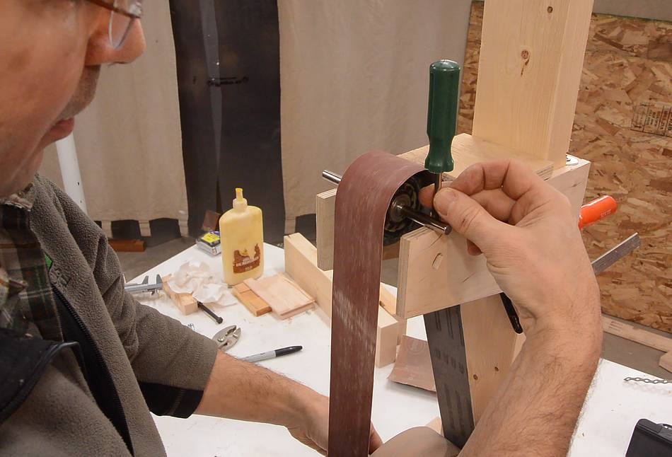
Then jigging the rest of the sander together just with clamps and testing
how the tracking worked,
just by inserting a nail in the slot to force the shaft up the slot.
Tracking wasn't working very well. I wasn't sure why, but with everything
held together precariously with clamps, I figured I should make it more solid
before working on that some more.
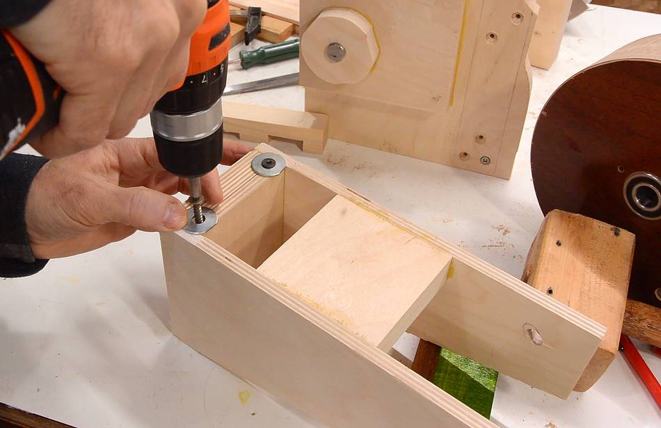
I drilled some screw holes in the plate that has the stub axle for the lower wheel,
used a short nail tapped into every hole to transfer the hole locations, then
used those divots to locate pilot holes, then screwed it together, with just two
screws at first.
Figuring out where the top mount goes for a 48" belt and marking it.
Then cutting a shallow slot where I marked it.
Two washers screwed into the top mount, overhanging the edge slightly, will engage
the slot in the top.
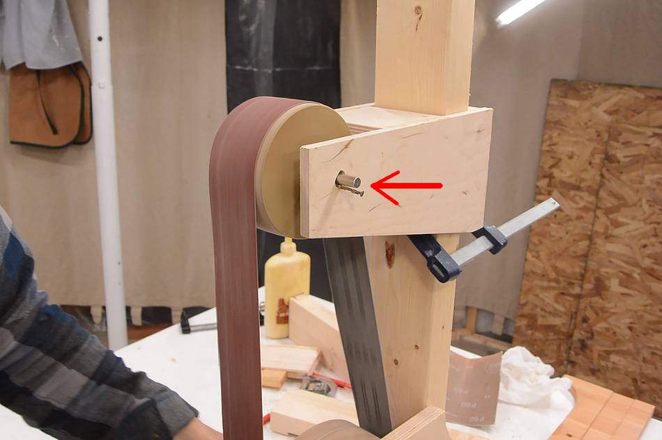
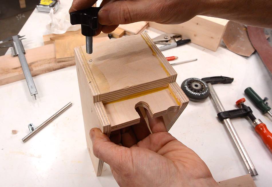
I cut a slot in the bottom back of the mount and installed a threaded insert in the
column.
This allows me to screw a thin piece of wood against the back of it,
which rotates the top mount to push the top wheel up for tensioning the belt.
But belt tracking adjustment still didn't work very well. I checked that
everything was sufficiently square (it was). I found my bottom roller had
a slightly negative crown to it, so I fixed that. That made it slightly
better but still didn't fix the problem.
I thought maybe the problem was with the shape of the top roller, so I switched
to a roller skate wheel, but my tracking adjustment still wasn't very
effective.
So I decided to investigate changing the tilt of the wheel, and the
rotation about the vertical axis (yaw angle) independently. Both of
those were able to change the tracking. But lifting the right side
caused the belt to track to the left, while moving the right side
forward also tracked it left. The way I had the slot, I lifted the
right side while also moving it back. Those two caused opposite
adjustments to the tracking, so they cancelled out. Oops! So I
really needed a slot that slanted in the opposite direction.
So I sawed the slot out a bit more for an opposite slant. It was a bit
of a hacked-up looking hole!
And with the slope I had, I needed something to push the axle forward for tracking
adjustment.
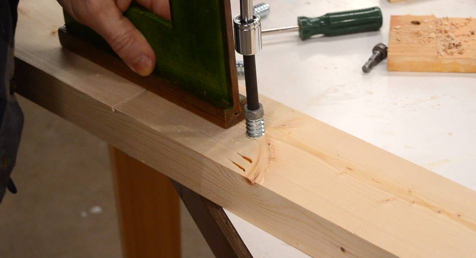
So I threaded a hole into the back of the bracket using a piece of threaded rod
with some slots cut into it with an angle grinder to act as a
wood thread tap.
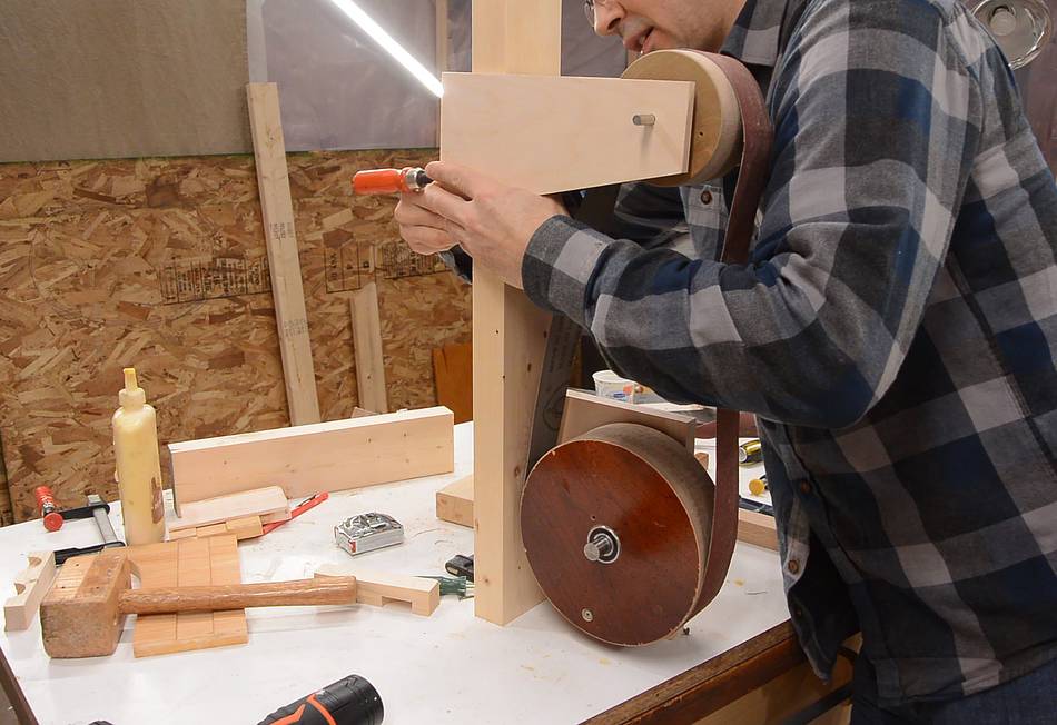
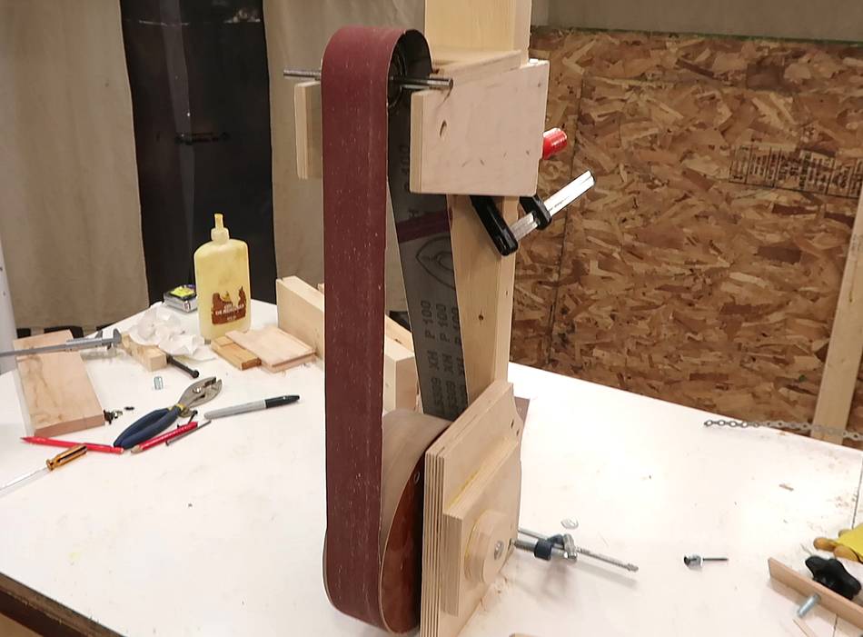
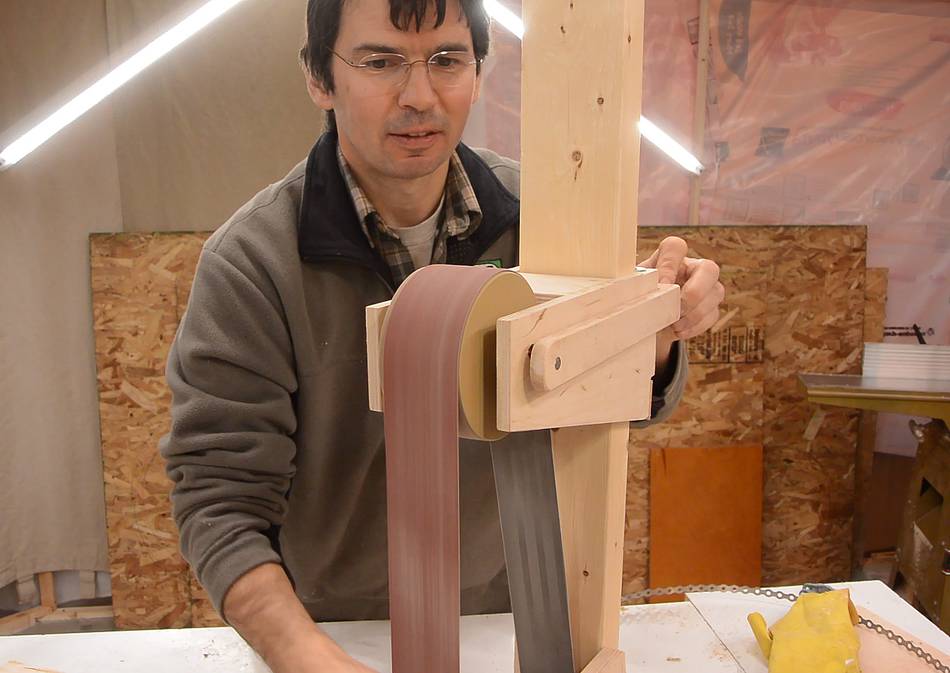
And with this change, tracking worked perfectly. I'm testing this by manually
spinning the lower wheel with a nail as a crank.
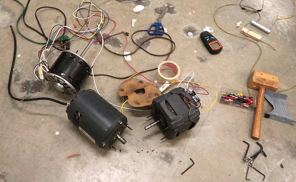
Before I go further with this build I need to figure out how to mount the motor,
and that depends on which motor I'm going to use. I need to decide which of these
three 1750 RPM motors I should use. I will have more on that next week.
 I wanted to experiment with building a belt grinder. But not having experience with
one, I wasn't sure if it was something I had much use for, so I didn't want to build
a typical belt grinder design such as
Jeremy Schmid's,
John Heisz's,
Cosmas Bauer's, or
this one.
I wanted to experiment with building a belt grinder. But not having experience with
one, I wasn't sure if it was something I had much use for, so I didn't want to build
a typical belt grinder design such as
Jeremy Schmid's,
John Heisz's,
Cosmas Bauer's, or
this one.

 1.5"x48" belt sander
 1"x42" strip sander build
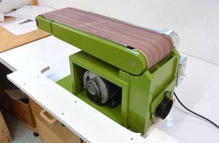 6"x48" belt sander build
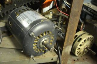 Where do you get your motors from?
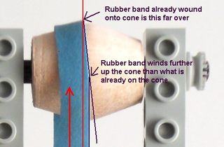 How crowned pulleys keep a flat belt tracking
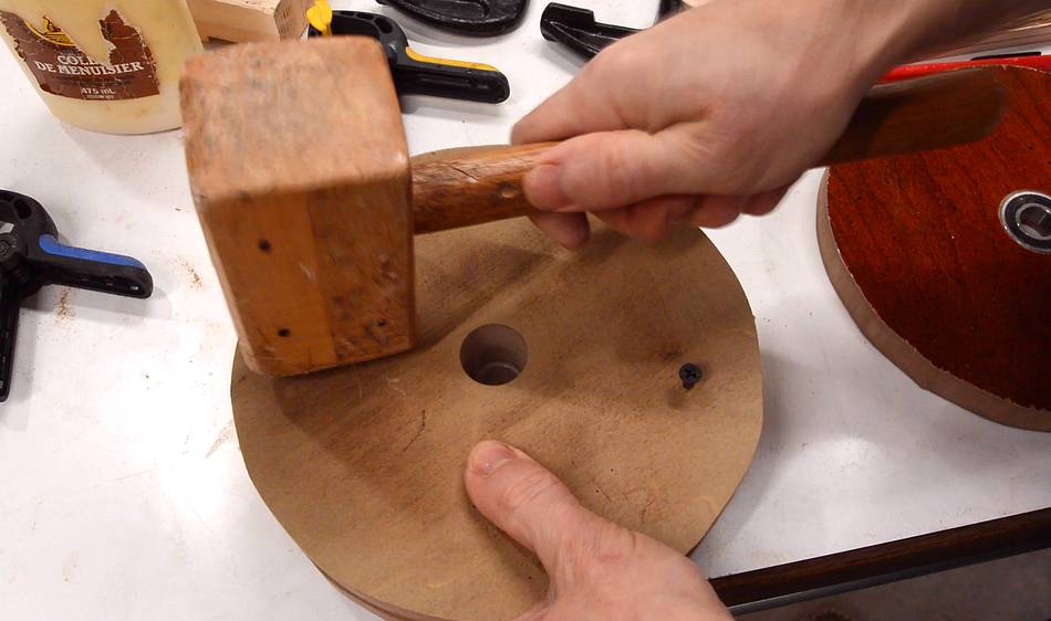