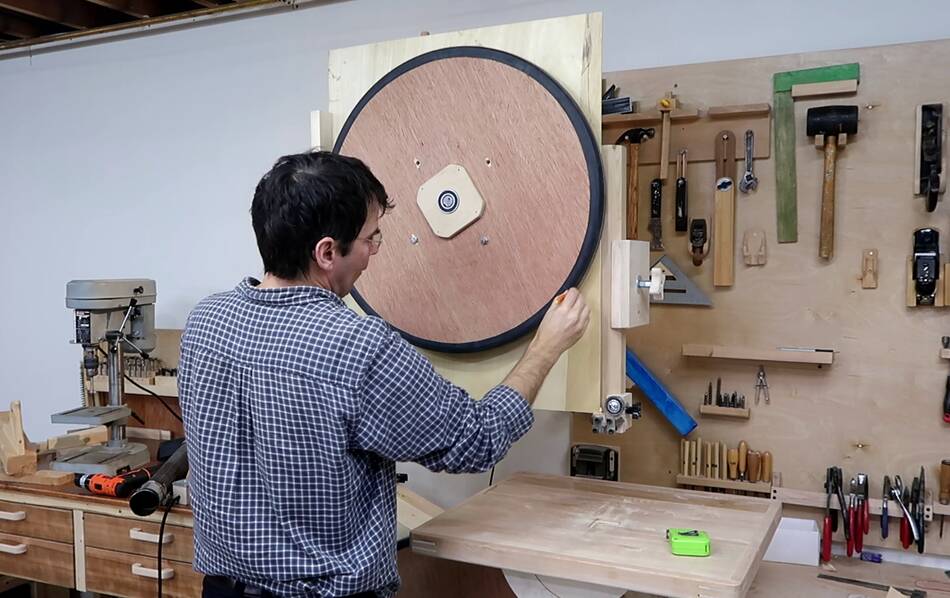
 It's always helpful to work with actual pieces to get a better sense
of how something will work out, and I hadn't finalized my CAD model
for the enclosure when I started building it.
It's always helpful to work with actual pieces to get a better sense
of how something will work out, and I hadn't finalized my CAD model
for the enclosure when I started building it.
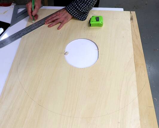
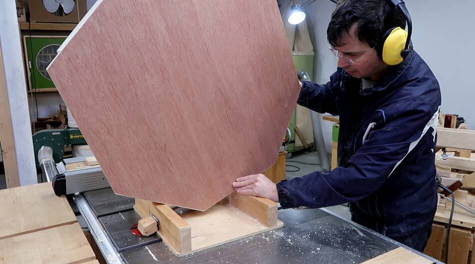
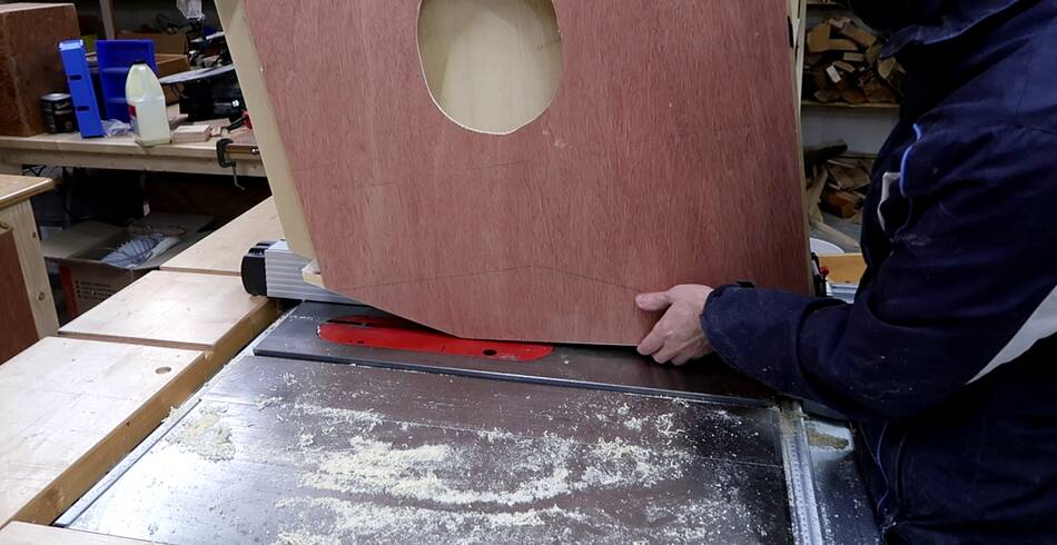
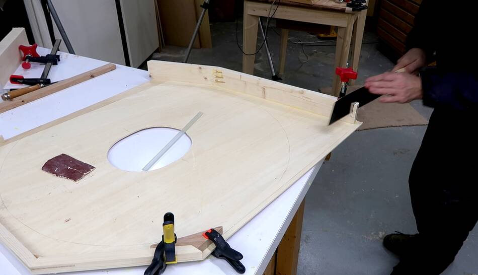
I started by cutting a big hole in a piece of thin plywood. I used 4 mm thick plywood, but I recommend using 6 mm or 1/4". I placed it behind the top wheel.
I traced around the wheel, then marked the 45° corners and the
sloped part on the bottom, then cut that out on the bandsaw.
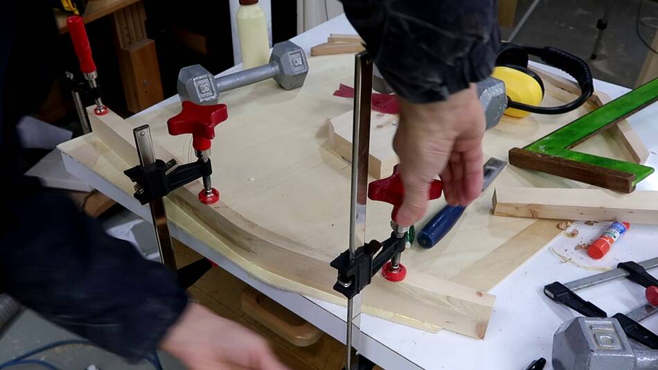
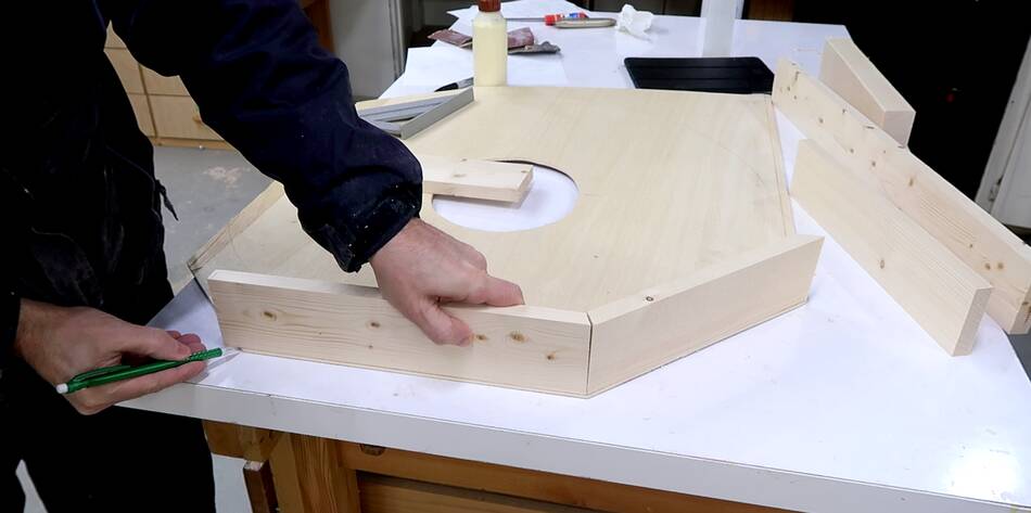 Making the pieces to go around the enclosure. These pieces have 22.5°
bevels to make the 45-degree mitered corners. I'm just holding the piece up
to my plywood back and marking the length off the plywood, then cut it to
length.
Making the pieces to go around the enclosure. These pieces have 22.5°
bevels to make the 45-degree mitered corners. I'm just holding the piece up
to my plywood back and marking the length off the plywood, then cut it to
length.
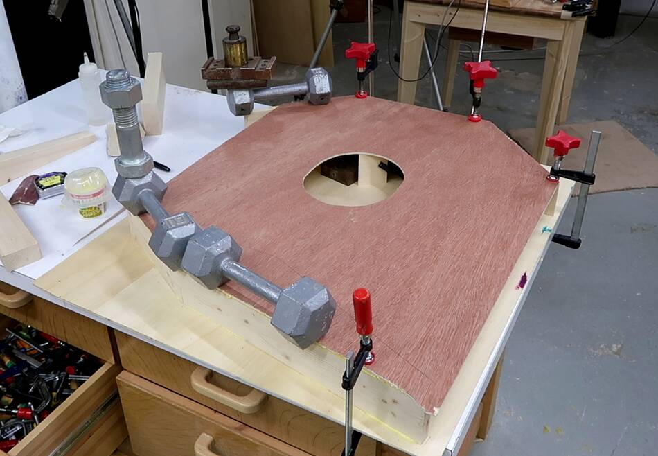
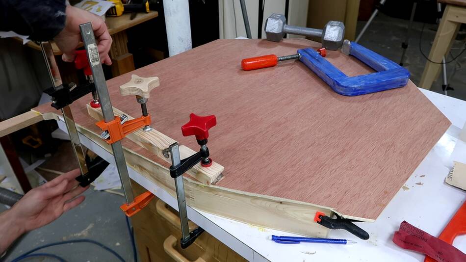
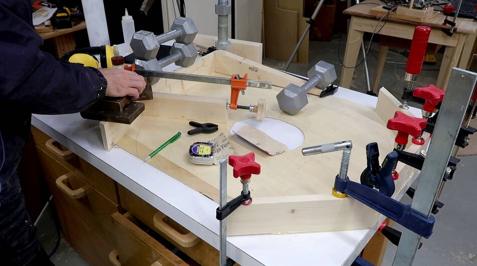 The top three pieces are glued and clamped (at right), then gluing on the two pieces
that form the bottom edge. I'm clamping everything down on my workbench
to make sure the result will be flat. The plywood I started with
was not particularly flat.
The top three pieces are glued and clamped (at right), then gluing on the two pieces
that form the bottom edge. I'm clamping everything down on my workbench
to make sure the result will be flat. The plywood I started with
was not particularly flat.
I'm using weights to hold down the two pieces that will make the bottom edge (at left), with longer pieces clamped to the sides of these to make sure they are square and don't tip over.
 Once the glue was dry from the previous glue-up, I applied glue to the other
edge of the boards I had just glued on, then flipped that over and glued it
onto what will become the front of the bandsaw, making a hollow box that
will be the top enclosure.
Once the glue was dry from the previous glue-up, I applied glue to the other
edge of the boards I had just glued on, then flipped that over and glued it
onto what will become the front of the bandsaw, making a hollow box that
will be the top enclosure.
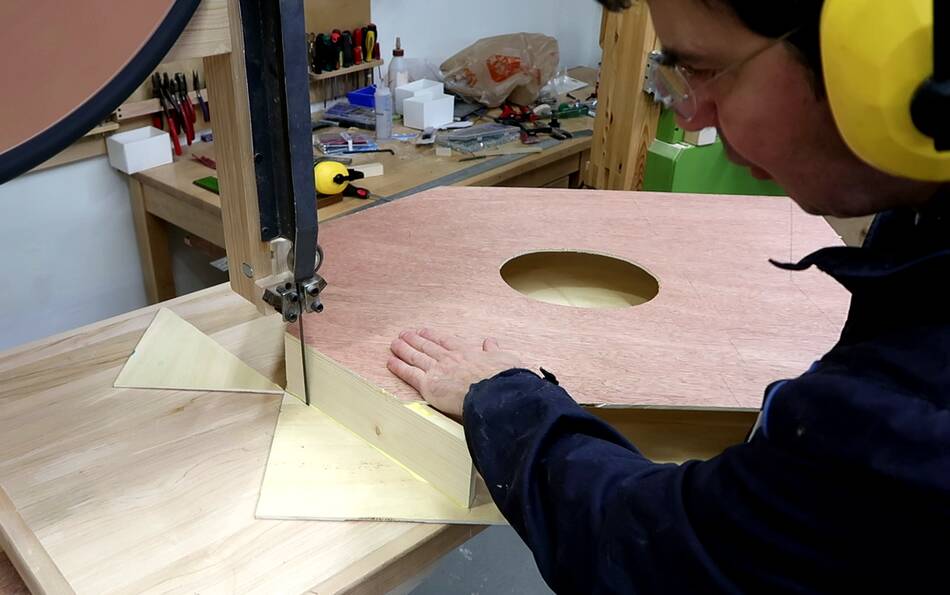
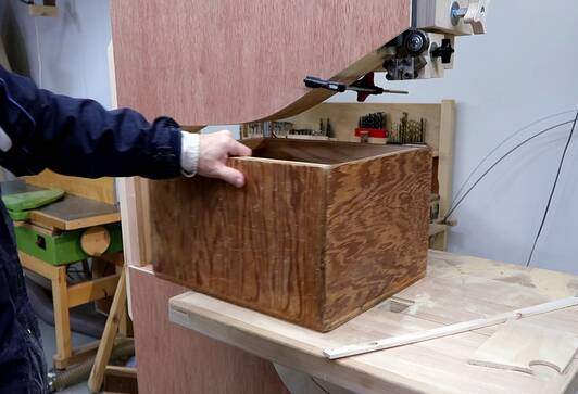
 I trimmed off the excess plywood on the bandsaw and sanded
the corners round.
I trimmed off the excess plywood on the bandsaw and sanded
the corners round.
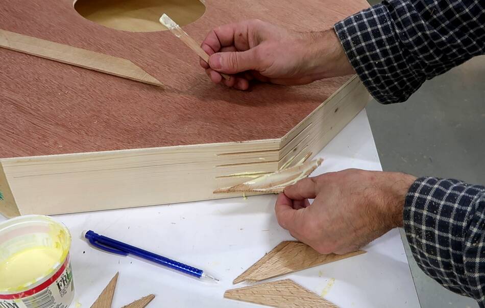
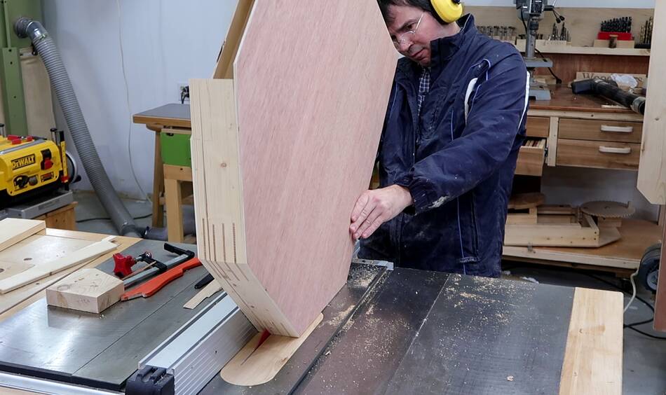
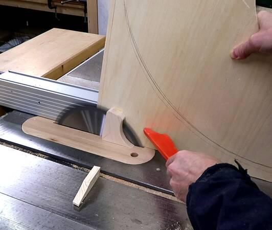
 Cutting some slots into the top corners for reinforcing splines by
sliding the cover over the saw blade on my small table saw sled.
Cutting some slots into the top corners for reinforcing splines by
sliding the cover over the saw blade on my small table saw sled.
 The bottom edge is too shallow an angle to cut the spline by sliding,
so I placed the cover on the saw and cranked the blade up to raise it
into the corner to make plunge cuts.
The bottom edge is too shallow an angle to cut the spline by sliding,
so I placed the cover on the saw and cranked the blade up to raise it
into the corner to make plunge cuts.
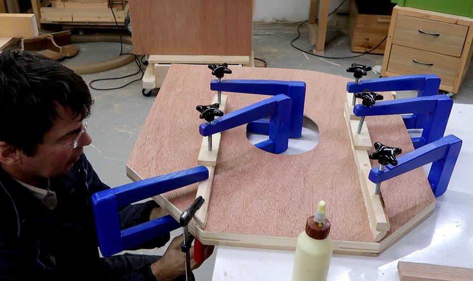
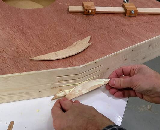 Gluing in the splines. The splines for the shallow angle (at right)
have a curved edge matching the saw blade's radius
Gluing in the splines. The splines for the shallow angle (at right)
have a curved edge matching the saw blade's radius
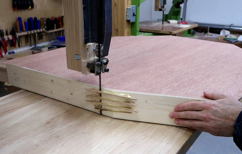 And trimmed off the excess, then sanded the splines all the way
flush. Cutting them flush with a chisel works well too.
And trimmed off the excess, then sanded the splines all the way
flush. Cutting them flush with a chisel works well too.
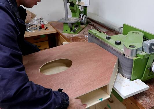
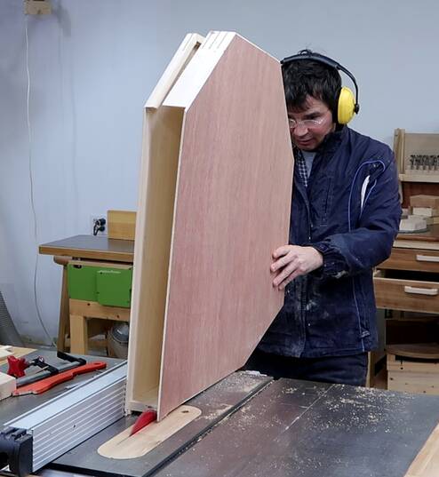 With the splines flush cut, it's time to cut the box into front and
back halves. The cut is offset from the center. The front cover has
more of the edge on the top and less on the bottom.
The rationale is that I want most of the top cover to swing away from
the wheels to make it easier to put a blade on, but on the bottom
side, I'd rather have the bulky part stay in place with the back cover.
With the splines flush cut, it's time to cut the box into front and
back halves. The cut is offset from the center. The front cover has
more of the edge on the top and less on the bottom.
The rationale is that I want most of the top cover to swing away from
the wheels to make it easier to put a blade on, but on the bottom
side, I'd rather have the bulky part stay in place with the back cover.
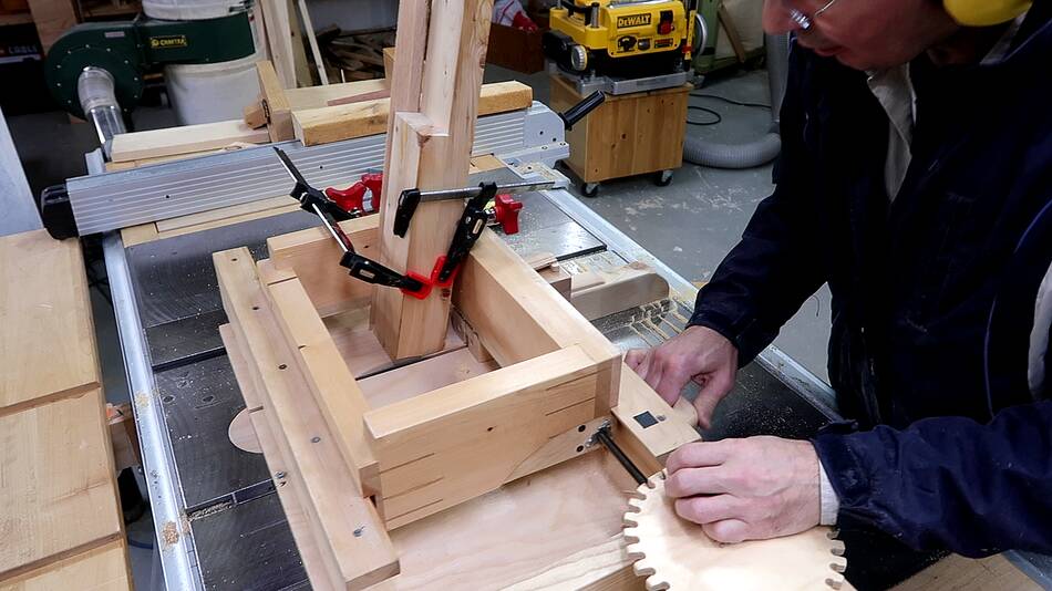
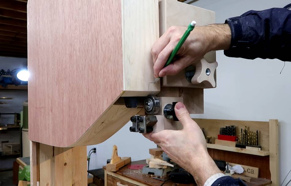
 I hadn't cut the post on the left side to it's final length yet, so with the
top cover in place, I mark where I need to cut off the post.
I hadn't cut the post on the left side to it's final length yet, so with the
top cover in place, I mark where I need to cut off the post.
 With the post cut to length, I check how it fits with the wheel. I have
lots of space above and below the wheel for vertical adjustments
to compensate for blade length variations.
With the post cut to length, I check how it fits with the wheel. I have
lots of space above and below the wheel for vertical adjustments
to compensate for blade length variations.
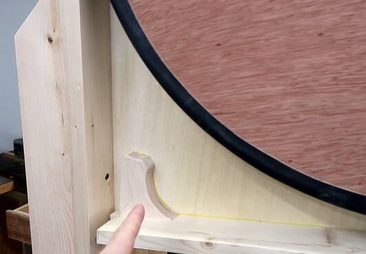 I then added an extra piece to the top left corner of the back
to screw into when attaching to the post (image at left, bottom), and another piece
on the bottom left to have something more solid when screwing it into the frame
(image at right).
I then added an extra piece to the top left corner of the back
to screw into when attaching to the post (image at left, bottom), and another piece
on the bottom left to have something more solid when screwing it into the frame
(image at right).
I didn't leave enough of a gap for the blade to go past on the bottom left, so I'm cutting
a bit off with a handsaw (image at left)
 With the cover as it was, I didn't quite like the look of it. I left too much space
inside the enclosure below the wheel, and I don't like how it looks with the enclosure
coming down that far. I fixed that in the plans, so if you are building from my plans,
you don't need to re-work it.
With the cover as it was, I didn't quite like the look of it. I left too much space
inside the enclosure below the wheel, and I don't like how it looks with the enclosure
coming down that far. I fixed that in the plans, so if you are building from my plans,
you don't need to re-work it.
I decided to make the bottom edge curved to closely follow the contours of the wheel. For that, I finger jointed the ends of two pieces of 2x4 at an angle to make the back for that bottom piece.
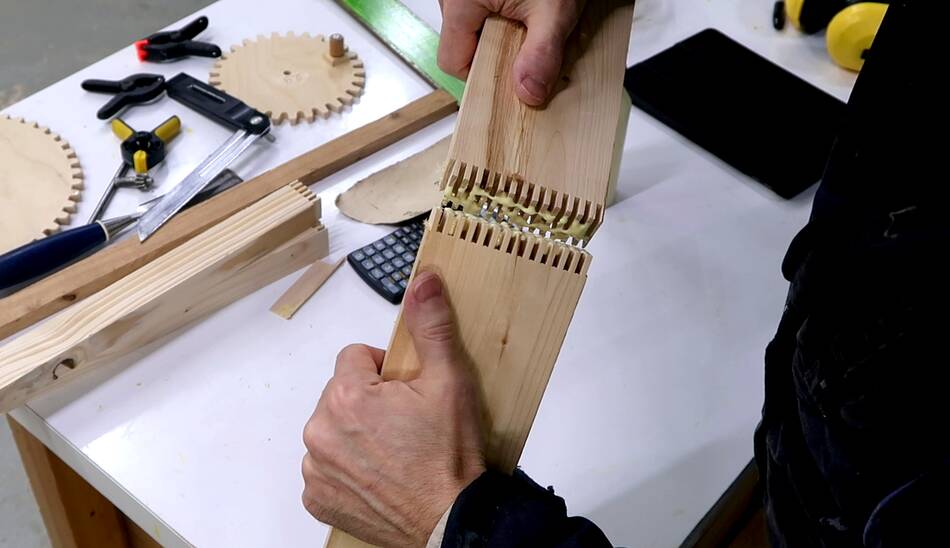
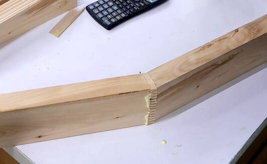 Gluing up the "bent" finger joint
 I had also built the top enclosure too shallow, so I added 1 cm thick
pieces to the edge to fix that.
I had also built the top enclosure too shallow, so I added 1 cm thick
pieces to the edge to fix that.
Checking my CAD model, I had the enclosure 1 cm deeper than what I built. So had I been following these dimensions, there would not have been any need to add an extra piece to make the enclosure thicker.
 Then cutting the bottom part of the enclosure off. I also decided to move the top
enclosure down by 1 cm to cut down on margin at the top. And with moving the bottom
of the enclosure up and moving the rest of it down, there would be enough plywood
left on the bottom to glue on a new bottom edge even after I cut off the old one.
Then cutting the bottom part of the enclosure off. I also decided to move the top
enclosure down by 1 cm to cut down on margin at the top. And with moving the bottom
of the enclosure up and moving the rest of it down, there would be enough plywood
left on the bottom to glue on a new bottom edge even after I cut off the old one.
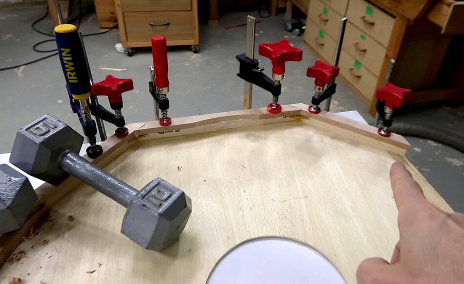
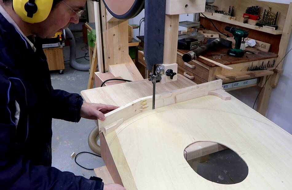
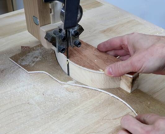
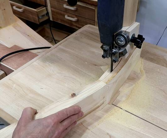 With my angled finger jointed piece placed on the bottom edge, I used my
beam compass to makr an arc around
where the wheel goes, then cut along those lines with my bandsaw.
With my angled finger jointed piece placed on the bottom edge, I used my
beam compass to makr an arc around
where the wheel goes, then cut along those lines with my bandsaw.
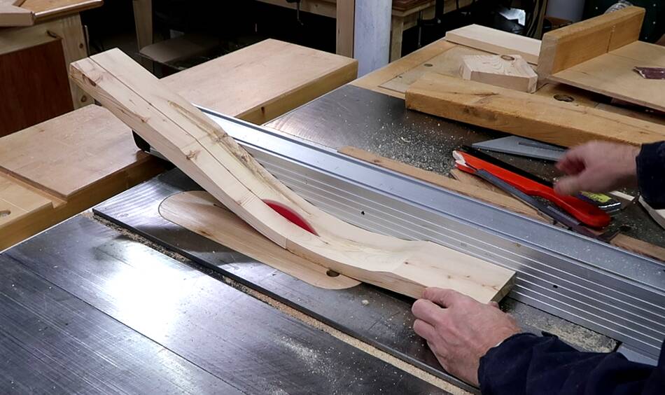 I split that part into two pieces. The wider part will go on the back of the
enclosure, the narrower part on the front. It was tempting to make this part
entirely part of the back enclosure, but I cut 2.5 cm to be part of the front
to help stiffen that up and force the plywood flat.
I split that part into two pieces. The wider part will go on the back of the
enclosure, the narrower part on the front. It was tempting to make this part
entirely part of the back enclosure, but I cut 2.5 cm to be part of the front
to help stiffen that up and force the plywood flat.
 Gluing the wider part onto the back part of the enclosure.
 Then placing the narrower part right on top of the wider part, using some
spring clamps on either end to hold it aligned, I glued on the front cover.
Then placing the narrower part right on top of the wider part, using some
spring clamps on either end to hold it aligned, I glued on the front cover.
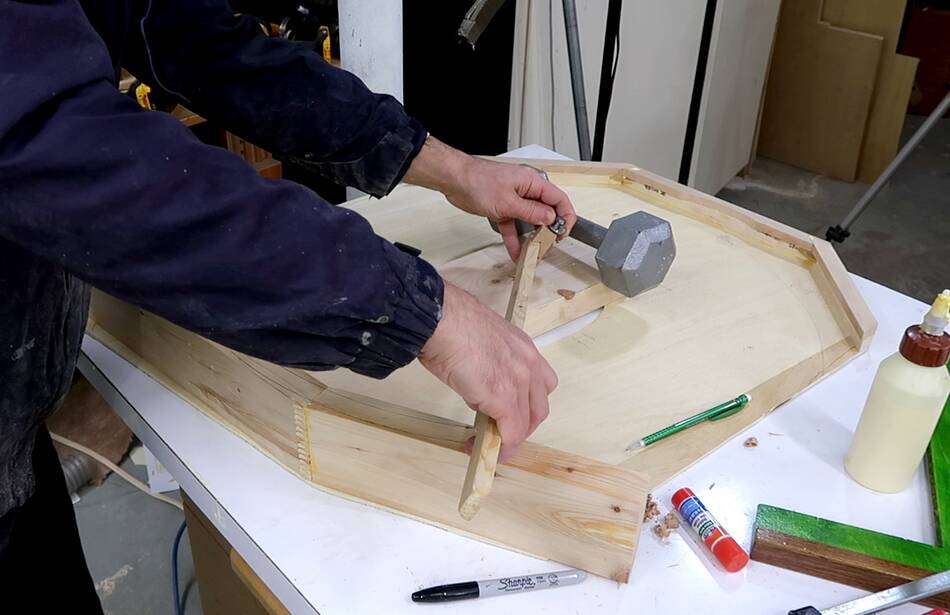
I lined up the top edge of the front cover with the top edge of the back
cover and weighed that down with a dumbbell to make sure everything was lined up.
 The thin (4 mm) plywood I was using wasn't very stiff, so I added some ribs to
the back of the top enclosure to stiffen it up. These ribs will attach to the
sides of the prongs in the top cover. If you make the cover out of good quality
1/4" plywood, you won't need these ribs.
The thin (4 mm) plywood I was using wasn't very stiff, so I added some ribs to
the back of the top enclosure to stiffen it up. These ribs will attach to the
sides of the prongs in the top cover. If you make the cover out of good quality
1/4" plywood, you won't need these ribs.
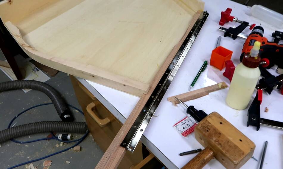
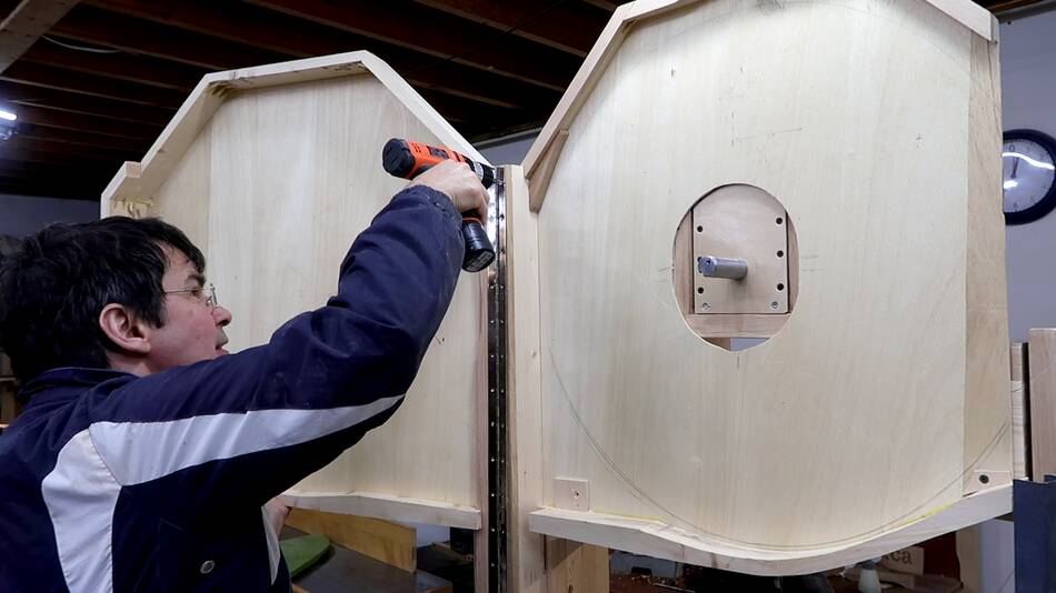
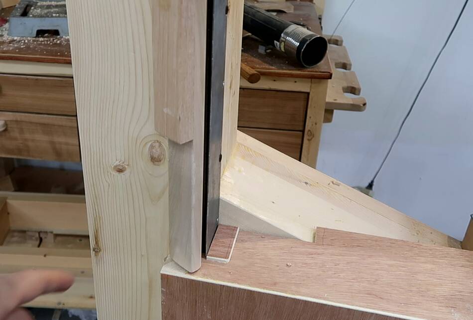
 With the two cover halves complete, I needed to add the piano hinge to allow
the top cover to swing open. But getting this all lined up is tricky.
With the two cover halves complete, I needed to add the piano hinge to allow
the top cover to swing open. But getting this all lined up is tricky.
I started by screwing the piano hinge to the front cover with just a few screws, then placed the front cover onto the bandsaw, lined it up and clamped it in place.
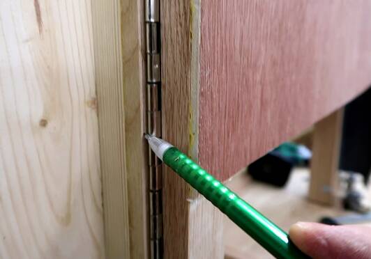
I then carefully marked where the piano hinge ended up.
 After that I removed the piano hinge from the front cover and lined it up with
the markings where it needed to go, then marked, center-punched and drilled
all the screw hole locations.
After that I removed the piano hinge from the front cover and lined it up with
the markings where it needed to go, then marked, center-punched and drilled
all the screw hole locations.
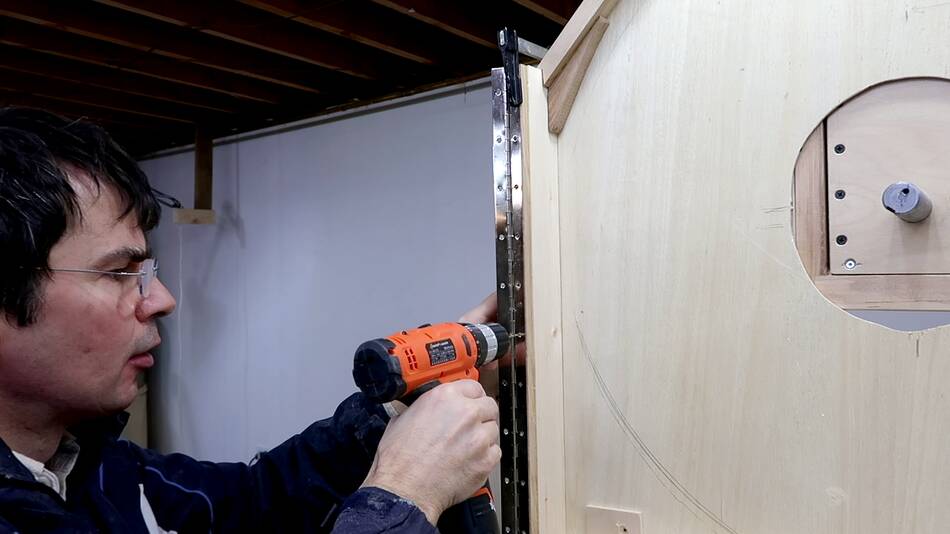
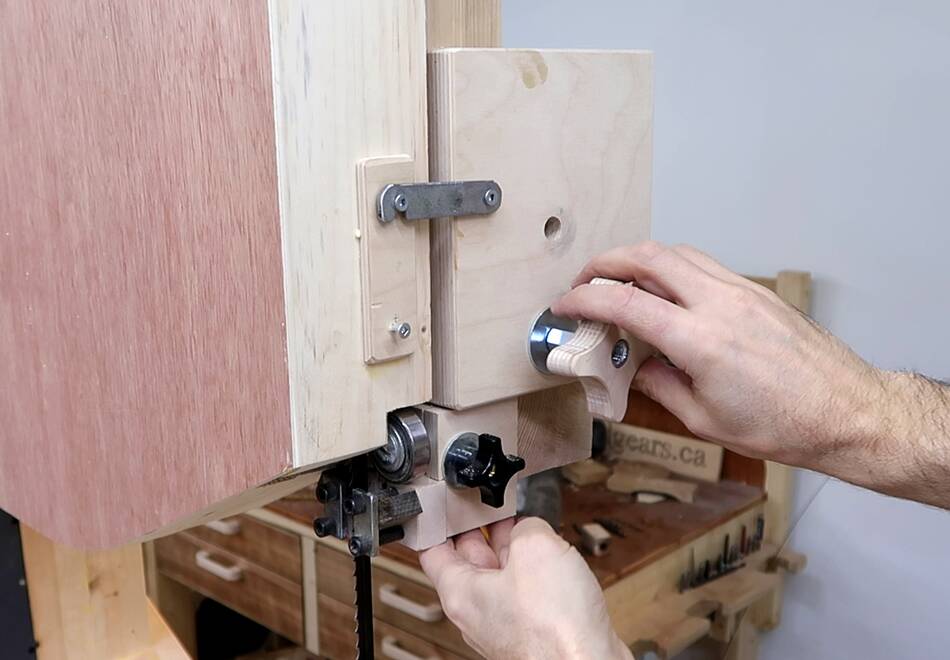
 I then screwed it in place with just two screws to test it.
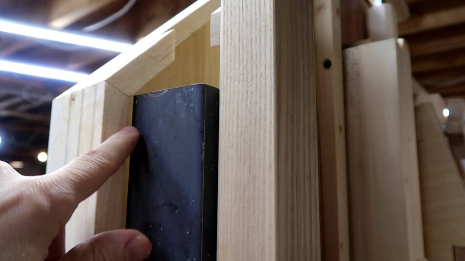
 With the cover swung closed, the blade guide coudln't be moved all the way up
without the thrust bearing hitting the cover. I marked what needed to be cut
off, then cut it.
With the cover swung closed, the blade guide coudln't be moved all the way up
without the thrust bearing hitting the cover. I marked what needed to be cut
off, then cut it.
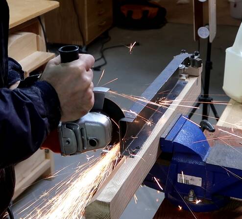 But the blade guide could still not be moved all the way to the top.
The blade guard was hitting the inside of the enclosure. I made
that piece a bit too long (longer than I had it in the CAD model), so I
shortened it using an angle grinder.
But the blade guide could still not be moved all the way to the top.
The blade guard was hitting the inside of the enclosure. I made
that piece a bit too long (longer than I had it in the CAD model), so I
shortened it using an angle grinder.
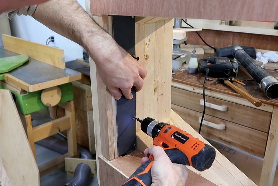
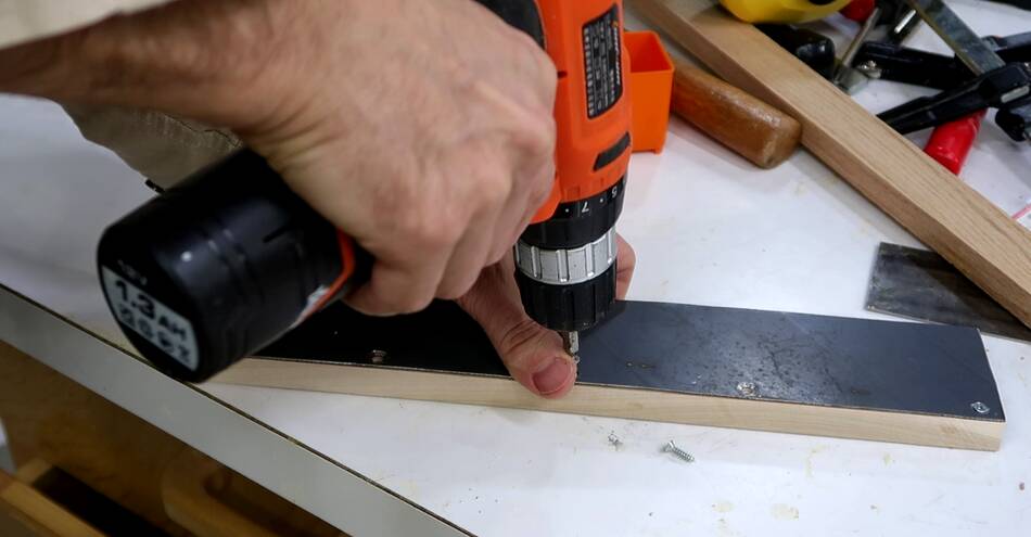 I still needed a guard for where the blade is on the left. In the past I
always made this out of wood, but this time I cut out a piece of sheet metal,
using the same material I used for the blade guard above the upper blade guide.
I screwed this to a small piece of hardwood
I still needed a guard for where the blade is on the left. In the past I
always made this out of wood, but this time I cut out a piece of sheet metal,
using the same material I used for the blade guard above the upper blade guide.
I screwed this to a small piece of hardwood
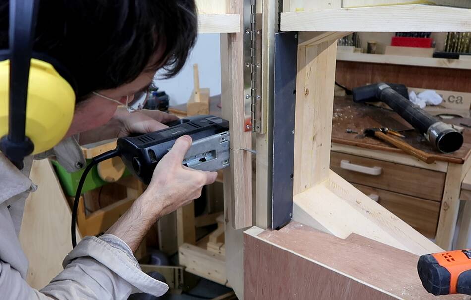
 Then screwing that on next to the bandsw blade.
 And another design change. Actually, this was already in my CAD model,
but I wasn't looking at it when I cut the piece.
I shortened the piece of the cover that the hinge attaches to.
And another design change. Actually, this was already in my CAD model,
but I wasn't looking at it when I cut the piece.
I shortened the piece of the cover that the hinge attaches to.
 Then glued a piece to the back of that. this piece is a bit narrower near
the top to fit around the hinge.
Then glued a piece to the back of that. this piece is a bit narrower near
the top to fit around the hinge.
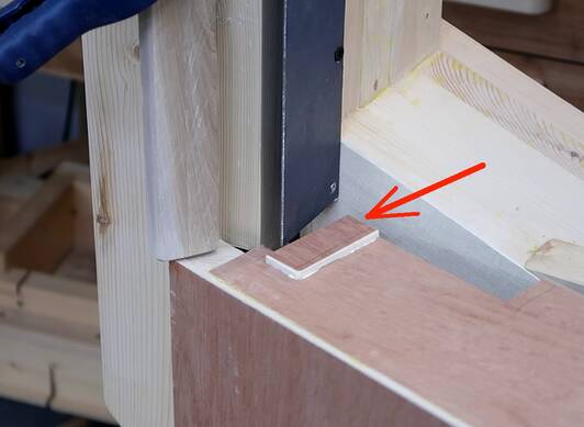
I also glued a small block to the top of the bottom cover to close off
the space around the guard, because I had cut the hole that the blade
passes through in the bottom cover a bit too large. When the bottom cover
is swung open, this just barely clears the blade guard as it swings away.
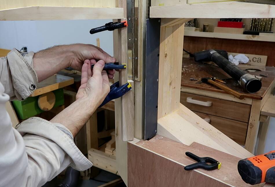
 And here is the finished blade guard arrangement. I had to round the back of
the piece I had just glued on so it doesn't get caught on the edge of the
metal blade guard to the right as the top cover is closed.
And here is the finished blade guard arrangement. I had to round the back of
the piece I had just glued on so it doesn't get caught on the edge of the
metal blade guard to the right as the top cover is closed.
The "notch" on the front is to make this part less deep. When cutting notches into the sides of long pieces, I always end up hitting the post on the left, so making the blade guard not come forward as far gives me a bit more space that way.
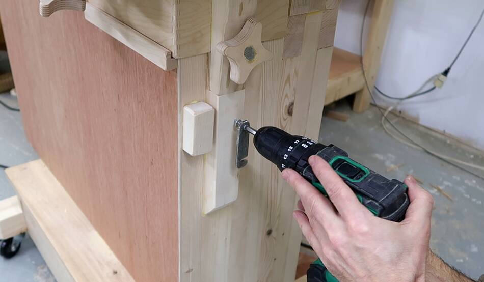
 I still needed to add something to hold the enclosure closed.
The bottom cover is already held shut by the blade guide
cover (right above where I'm drilling at left), but that cover needs to
be removed when tilting the table, so I still needed something
to hold it shut.
I still needed to add something to hold the enclosure closed.
The bottom cover is already held shut by the blade guide
cover (right above where I'm drilling at left), but that cover needs to
be removed when tilting the table, so I still needed something
to hold it shut.
I made this latch by drilling a hole in one end and cutting a notch in the
other end of a strip of metal. if you dont' want to make this, you
could substitute a "hook and eye door latch", or a "screen door hook".
For me, it was easier to make a latch than go and buy one. Also these screen
door hooks are difficult to model in SketchUp.
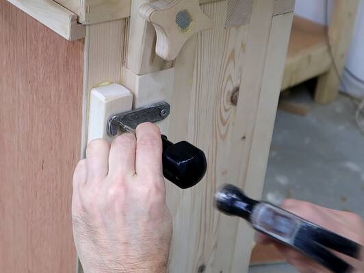
 After screwing it on one end, I hook it over an awl and use that to
center punch where the screw it hooks onto should go.
After screwing it on one end, I hook it over an awl and use that to
center punch where the screw it hooks onto should go.
The top enclosure latch is attached to the guide post clamp. But the guide post clamp has a second position for moving the blade guide all the way up, so the latch has two screws that it can hook onto, the lower one for the normal clamp position, the upper one for when the blade guide clamp is in the upper position when the blade guide is all the way up.
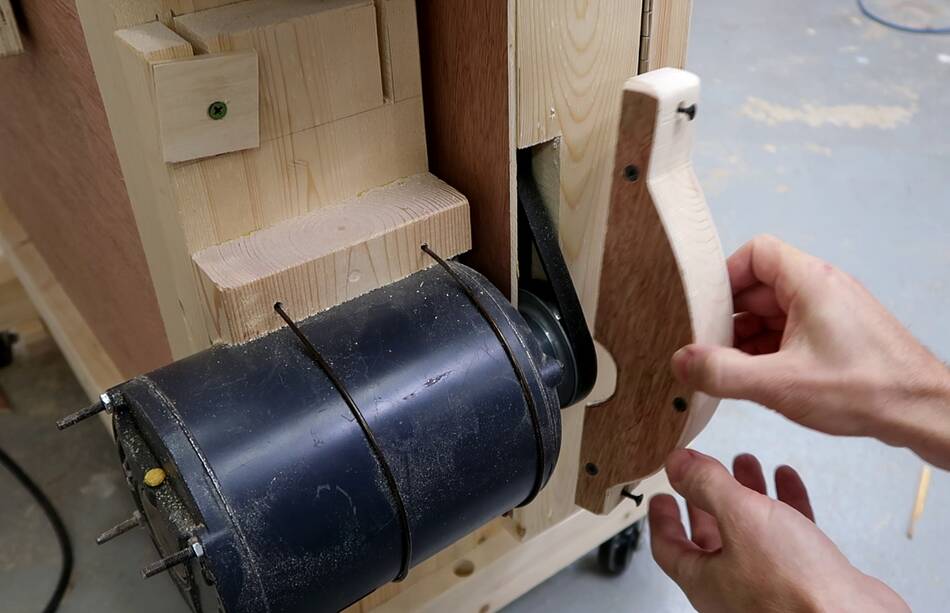
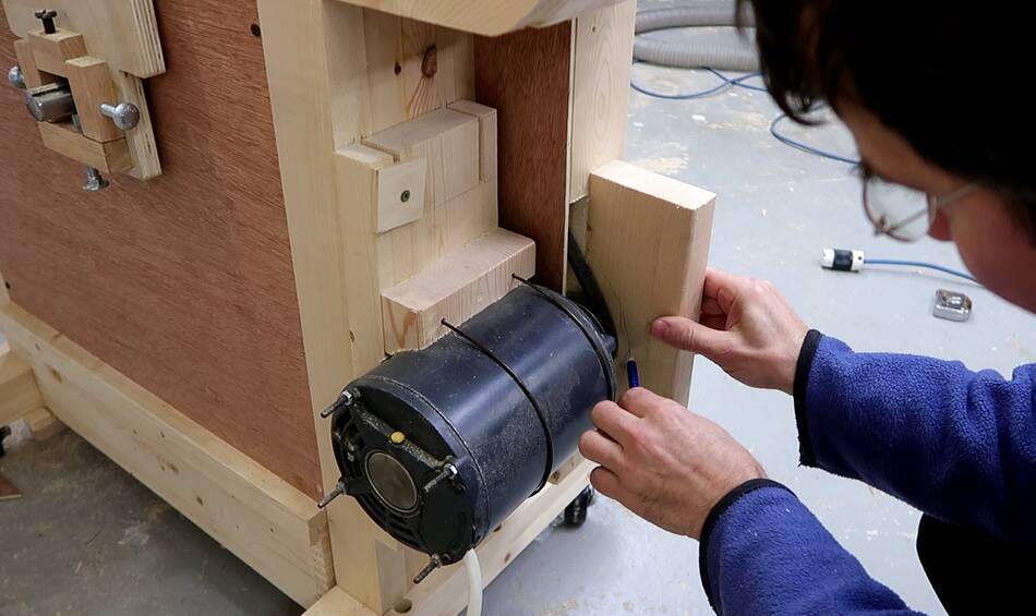 I still needed a guard to go around the drive belt. I held a piece of 2x4
wood next to the belt and traced around the belt, leaving 1 cm of margin.
I still needed a guard to go around the drive belt. I held a piece of 2x4
wood next to the belt and traced around the belt, leaving 1 cm of margin.
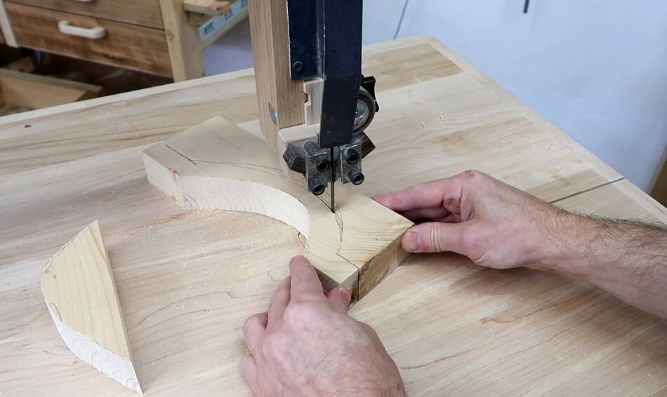 I then cut that piece out and also cut around it, then glued a piece of
plywood to one side of it.
I then cut that piece out and also cut around it, then glued a piece of
plywood to one side of it.
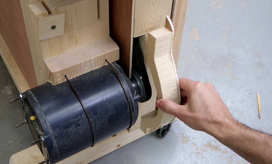 Checking how this piece fits around the drive belt.
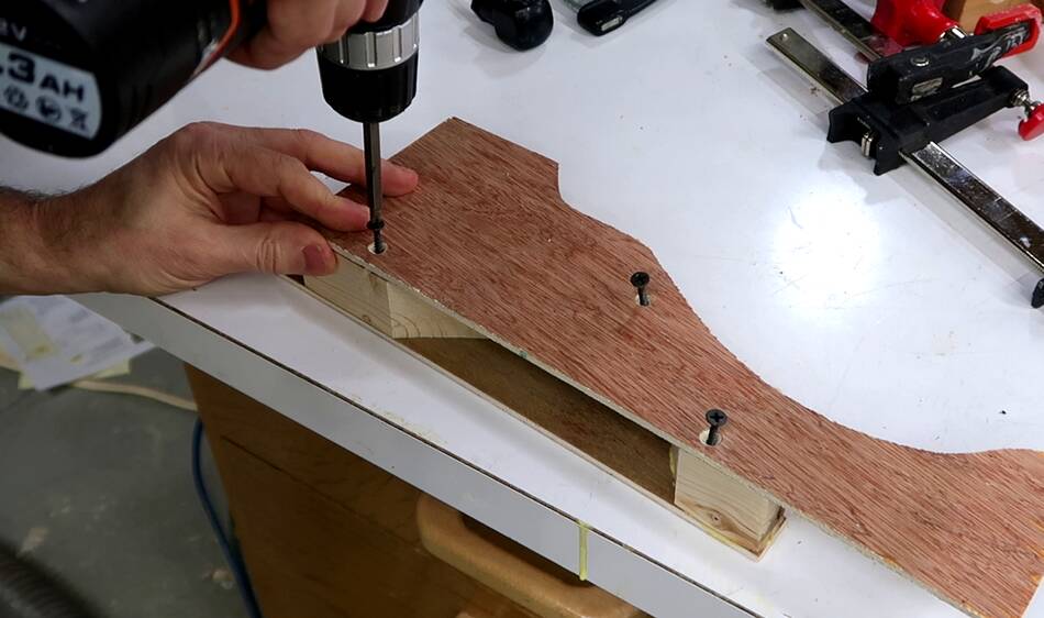
 The plywood for the other side is just screwed on,
then trimming the excess plywood on the bandsaw and sanding it smooth.
The plywood for the other side is just screwed on,
then trimming the excess plywood on the bandsaw and sanding it smooth.
 After checking the fit, I removed the screwed on plywood, cut a notch
to fit part of the pulley protruding through the enclosure, then screwed
that in place. Depending on your motor and pulley, you may or may not need
to cut such a notch on yours.
After checking the fit, I removed the screwed on plywood, cut a notch
to fit part of the pulley protruding through the enclosure, then screwed
that in place. Depending on your motor and pulley, you may or may not need
to cut such a notch on yours.
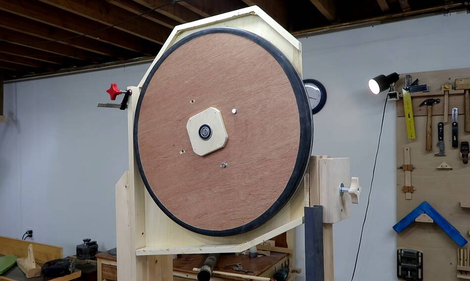
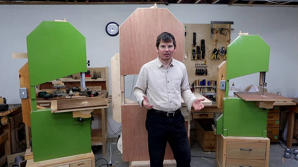 And with the enclosure complete, the bandsaw is the final shape that it's going
to be. I still need to paint and varnish it, balance the wheels, and add the
electrical switch.
And with the enclosure complete, the bandsaw is the final shape that it's going
to be. I still need to paint and varnish it, balance the wheels, and add the
electrical switch.
For reference, I have it between my big 20" bandsaw on the left, and my 16" bandsaw on the right. I wish I still had a 14" bandsaw to put it next to just for scale.
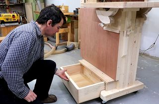 Bottom enclosure for this bandsaw
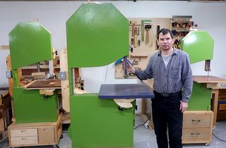 26" bandsaw build
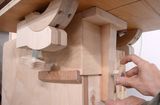 20" bandsaw enclosure
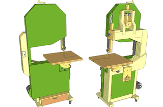 Buy plans for the 26" bandsaw