Michael Sullivan's router gear cutting
 Michael Sullivan writes:
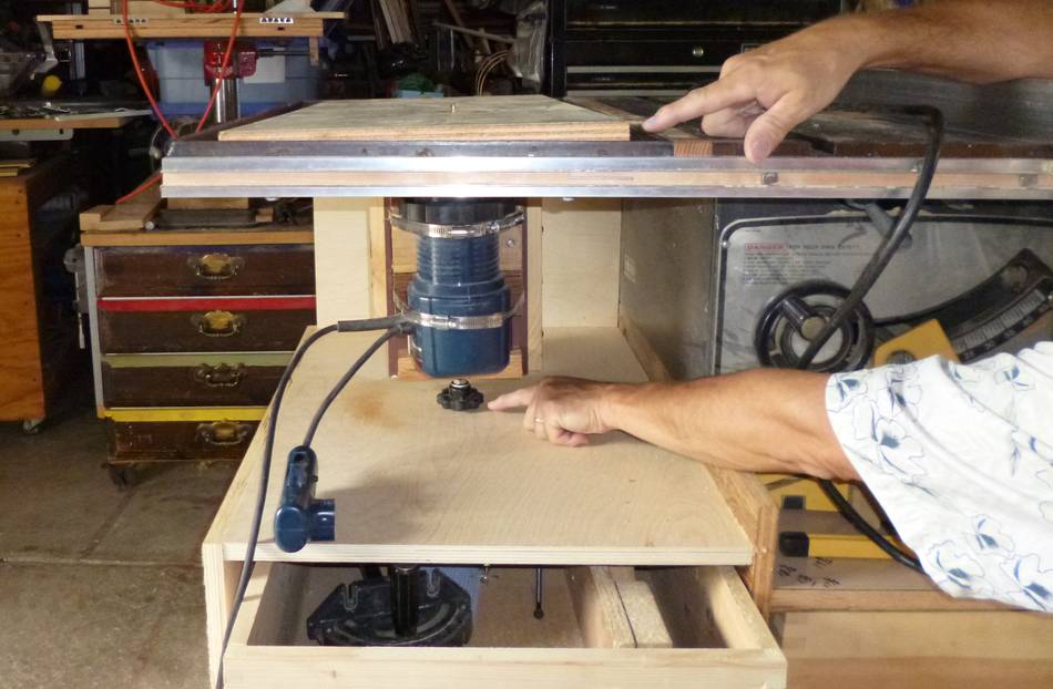
When I rebuilt my table saw cabinet I decreased the space under my router lift making it too small for the handle on the bottom of the lift screw. I decided that a set of co-planar gears would allow me to raise and lower the lift the easiest.
While looking at your on-line gear generator, I realized that the concept of unwinding a "string" from the base radius to show the point of contact was exactly the same as "rolling" the base circle along a straight edge. Both were tangents. It occurred to me that if I rolled a base circle along the router fence, a half exposed straight cutter would be like the "point of contact" unwound from the base circle. Further if sized right I could cut both sides of the "notch" by just continuing to roll past the cutter. I used your template generator to get the base radius and gear tip radius. Initially I used an angle of 23°, a pitch of 12.7mm and 20 teeth.
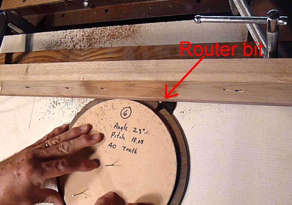
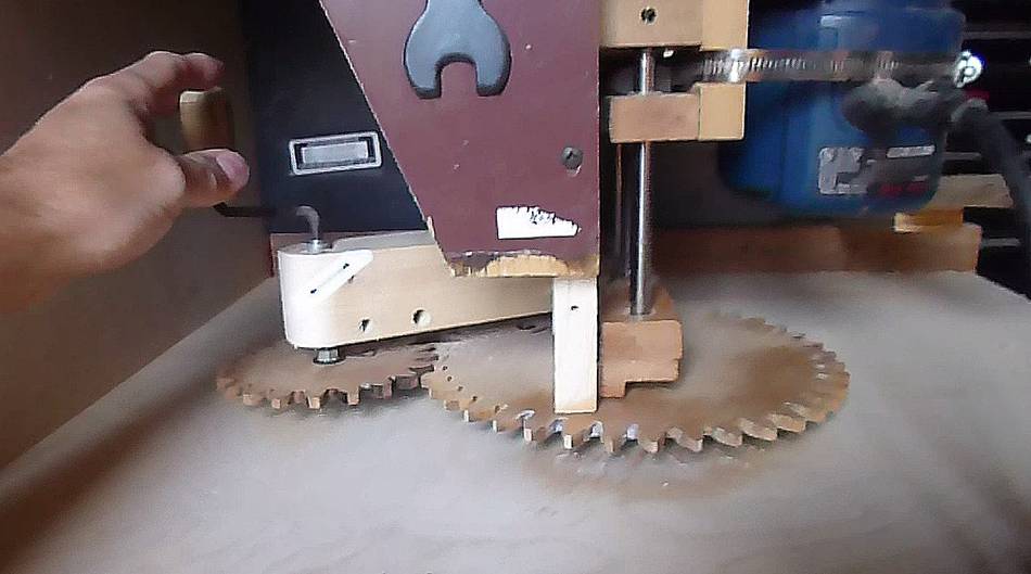
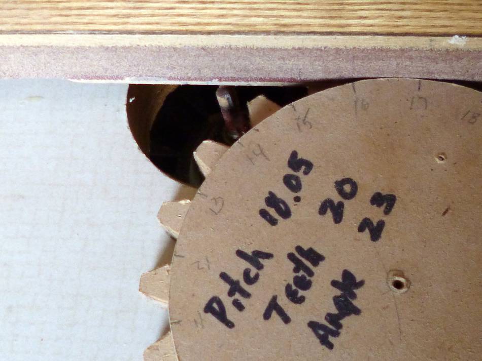 Fence and cutter along with a disk and cut gear.
 I quickly realized three things;
1) the tooth spacing from the generator was too small for a 1/4" bit,
2) the fence was too slippery to "roll" the base circle disk and
3) I needed to feed the material from right-to-left not left-to-right as I had done.
 So I measured the spacing from the first template and increased the
pitch to 18.05 mm. (I know, I know: only two digits are significant!). I
also put some double sided tape on the fence face.
So I measured the spacing from the first template and increased the
pitch to 18.05 mm. (I know, I know: only two digits are significant!). I
also put some double sided tape on the fence face.
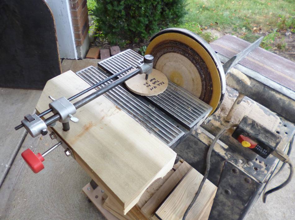
Having set up a band saw circle cutting jig on my sander making pretty round disks was fast and easy so I just made two re-scaled pieces.
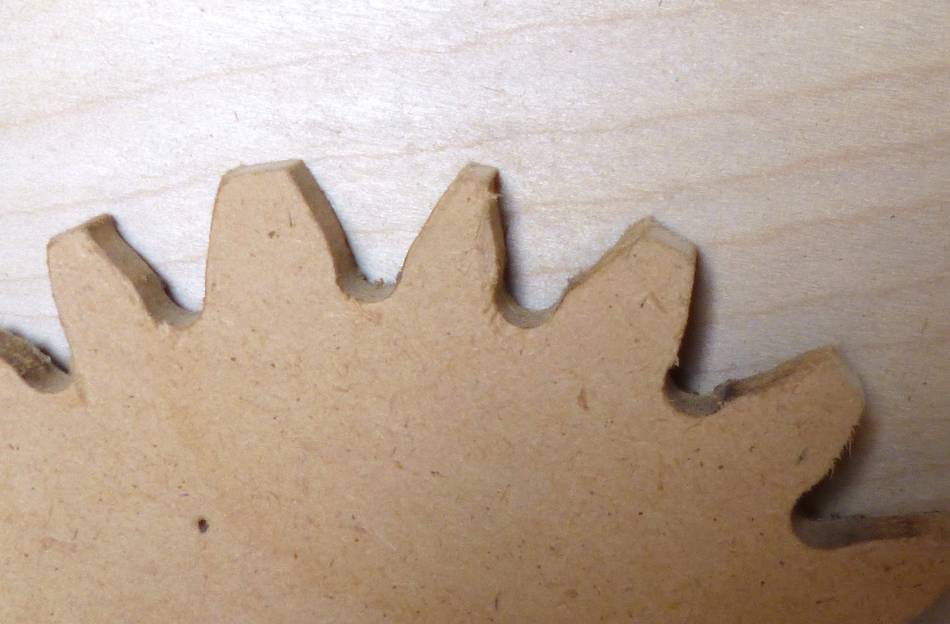 Naturally the two-sided tape did not work and I got highly
distorted teeth. The soft glue of the tape has some "give" to it.
Naturally the two-sided tape did not work and I got highly
distorted teeth. The soft glue of the tape has some "give" to it.
 So I used contact cement to attach some sandpaper to the face of the
fence to give the base circle disk something more ridgid to grip.
So I used contact cement to attach some sandpaper to the face of the
fence to give the base circle disk something more ridgid to grip.
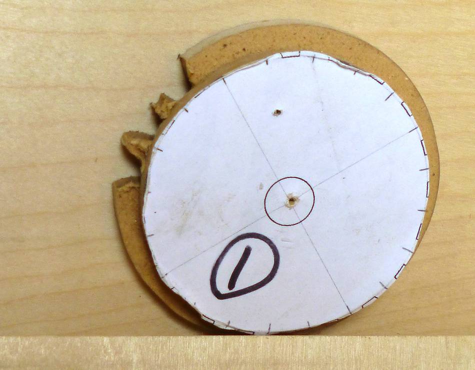
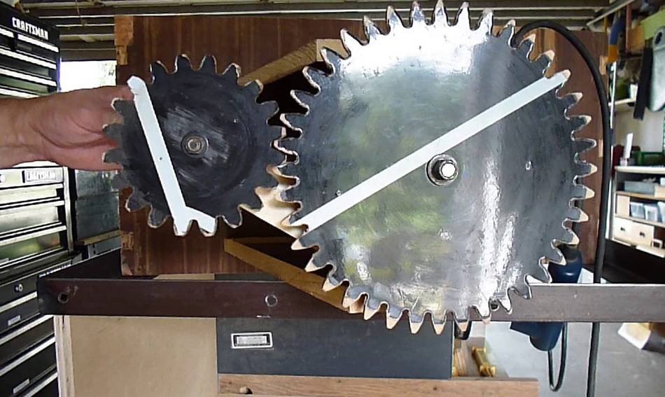
 The starting point is really arbitrary but the index
dividing lines need to be placed consistently at the same spot along the
fence. I found numbering the dividing lines helped me keep track of
where I had already been. The third gear turned out pretty good.
The starting point is really arbitrary but the index
dividing lines need to be placed consistently at the same spot along the
fence. I found numbering the dividing lines helped me keep track of
where I had already been. The third gear turned out pretty good.
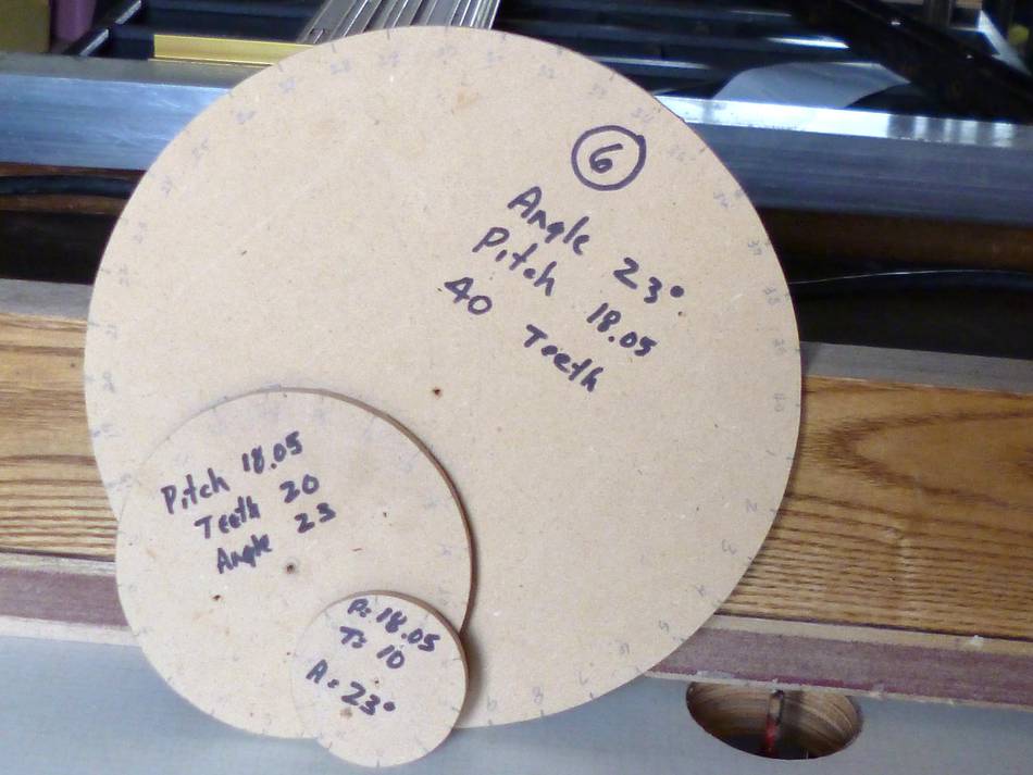
 I then made a 10, another 20 and a 40 tooth sized disks and cut them.
At left, base circles with index marks around the circumference. The 40 tooth seems to
provide me with the right physical size to allow cranking and the right
"force" level to easily raise and lower the lift. I did not have to
sand, file, or fine tune any of the disks. I simply removed the
whiskers and started using them.
I then made a 10, another 20 and a 40 tooth sized disks and cut them.
At left, base circles with index marks around the circumference. The 40 tooth seems to
provide me with the right physical size to allow cranking and the right
"force" level to easily raise and lower the lift. I did not have to
sand, file, or fine tune any of the disks. I simply removed the
whiskers and started using them.
See also:
 Bandsaw vs CNC
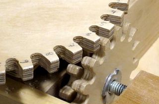 How to make gears
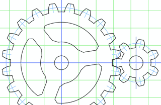 Gear generator
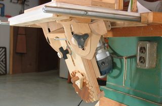 Router lift
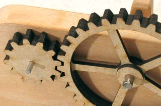 Cutting gears
Back to my Woodworking website