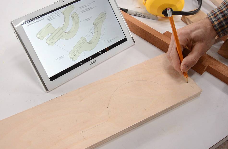
Although I include printable 1:1 templates in the plans, I figured
this time I'd just draw the shape from the drawings on my tablet. This was partially
inspired by windows 10 not getting along that well with my printer, and partly to
show that you can build the pantorouter even if you don't have a printer.
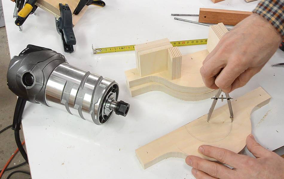
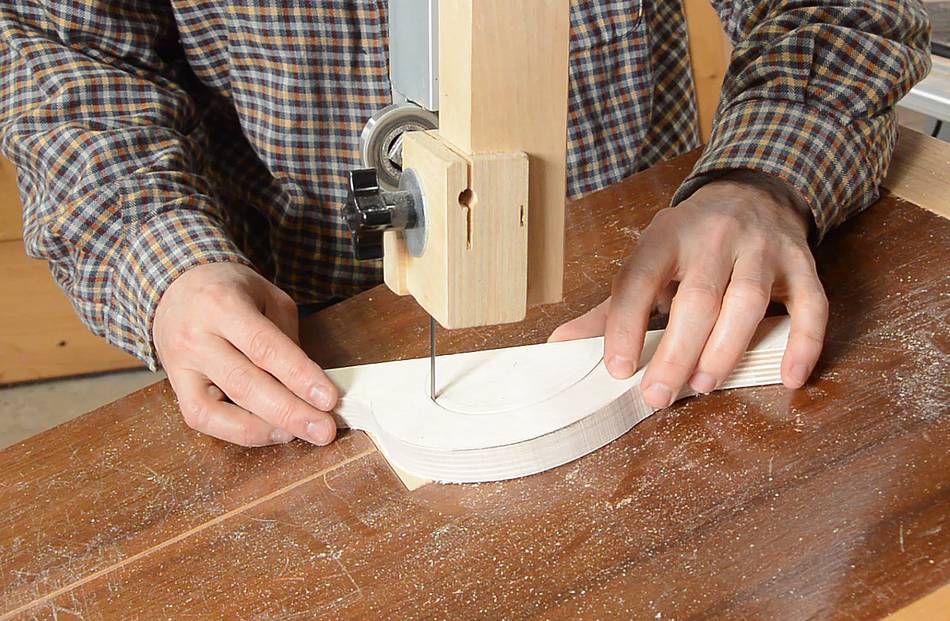
The most complicated shapes are the router mount, but it really didn't take that long
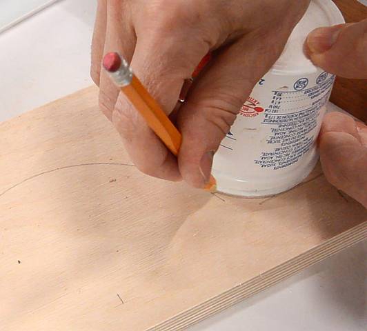
to draw it from dimensions on a piece of plywood. I used an empty yogurt cup to draw
the arcs that join the main arc and the straight part of the router mount.
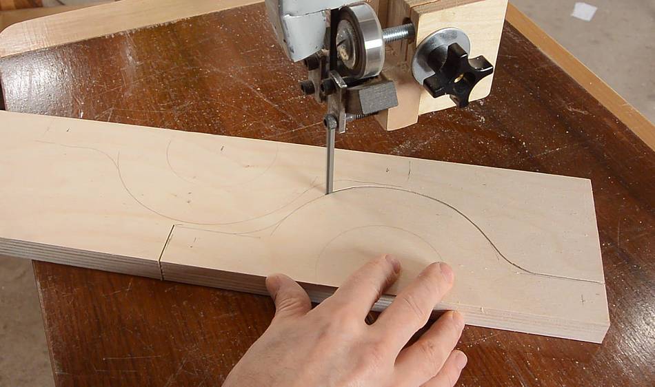
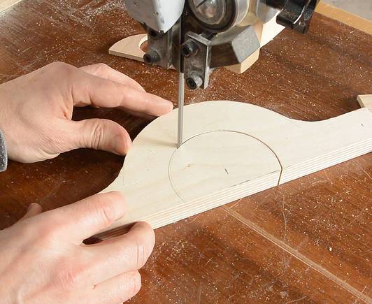
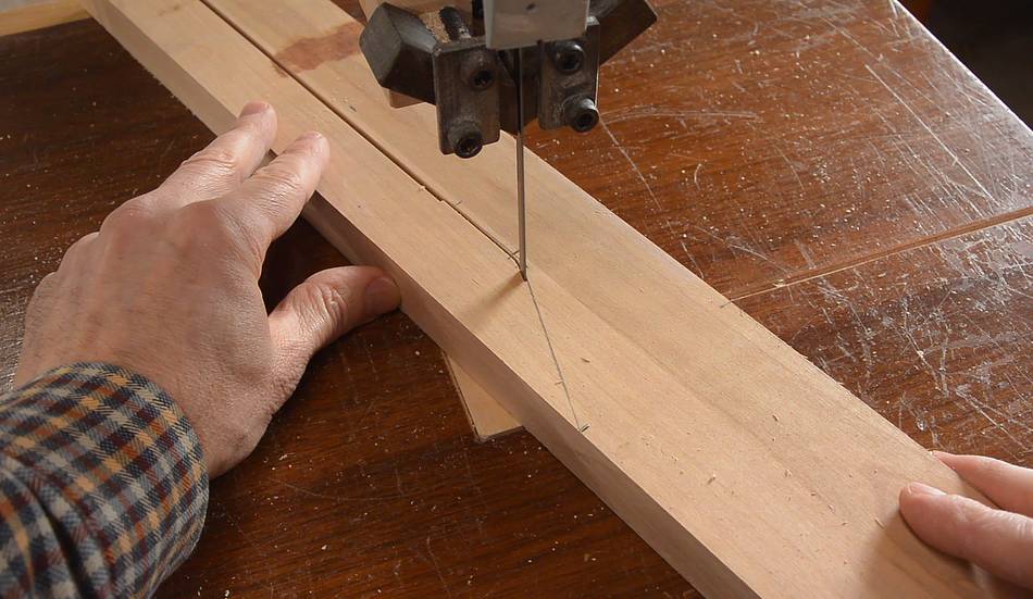
I cut it out on the bandsaw. If you have a CNC router and a bandsaw, I highly
recommend cutting it out on the bandsaw. It will take much less of your time that way!
I'm using 18 mm thick baltic birch plywood. This part really needs to be made of plywood,
Solid wood is too likely to break across the grain and that could cause the router to jump
out of the machine unexpectedly.
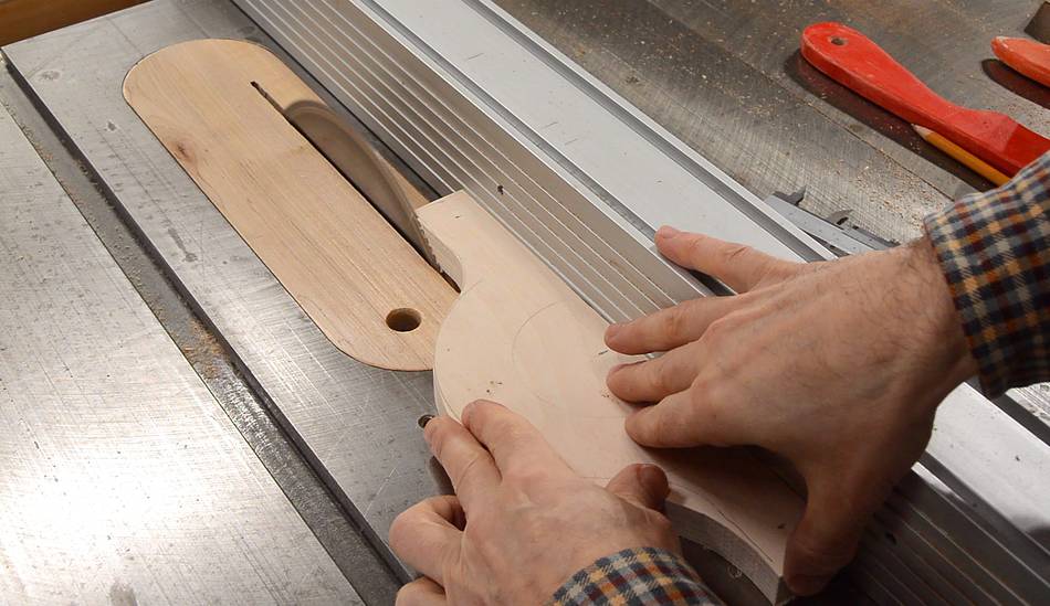
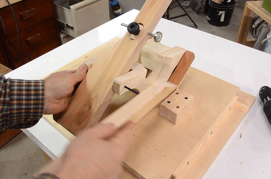
Trimming some of the square parts on the table saw.
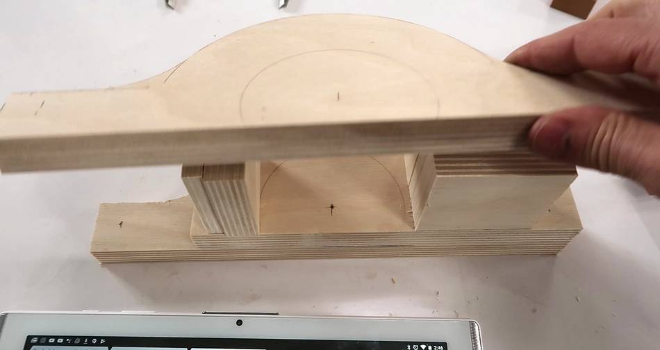
Stacking the pieces together to see how it will fit.
I ordered a Hitachi router off of Amazon. I picked this one because it claims
to be quieter than others (it is quieter), and it's not too expensive.
It has a slightly smaller diameter but still has a 1/2" collet.
I was hoping it would be lighter too, but it's quite heavy.
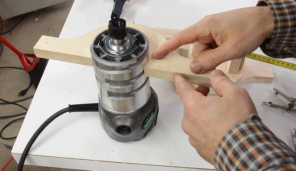
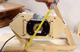
I measured its diameter (83 mm) then drew circles of the diameter on the plywood,
then carefully cut that out on the bandsaw.
At first the fit was very tight, but the aluminium router body left some marks
on the wood where it rubbed, so I cut a fraction of a millimeter off those
areas, and then the fit was nice and snug.
The back-most layer has a bigger hole for the non cylindrical part of the router.
I cut it conical by tilting the bandsaw table.
I then glued it together in stages, first the back two layers, being very careful
that the alignment was good.
While the glue dried on that, I worked on the other links of the pantograph.
The short and long links are mostly rectangular parts. I figure most people
already know how to cut rectangular parts on the table saw, so I didn't take
any pictures of that. (If you don't know how to cut rectangular pieces on
the table saw, you should not attempt this build.)
I used Mahogany for the long parts of the links. Ideally I'd use something harder,
but I think the colour of it will contrast nicely, and also, mahogany is a very stable
wood, so fewer changes in shape with humidity changes.
You could also make these parts out of baltic birch plywood.
I used a marking gauge set to 1.5 cm to score two intersecting lines for where the
holes go, then drilled them with a brad point drill bit.
A word of caution - if the wood has a very pronounced grain pattern, such as oak or ash,
and it's at an angle to how you are drilling, especially with a metal (non brad-point)
drill bit, the grain can cause the drill to wander along the grain as it drills.
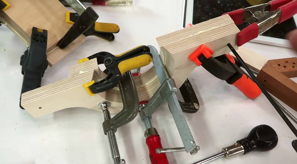
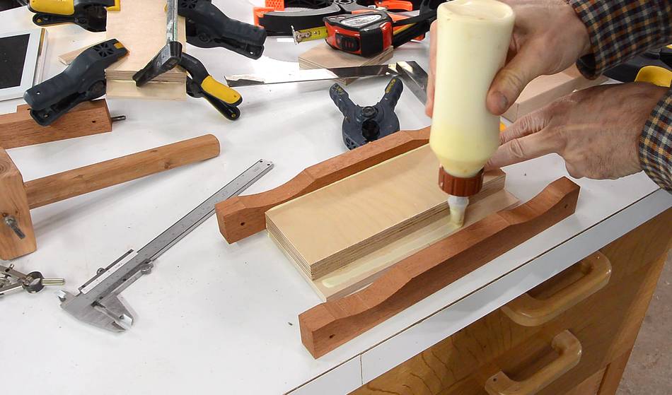
Gluing together the link. I started by gluing one of the mahogany pieces to the plywood
that is on the bottom (as viewed in the photo), then let the glue dry for about
20 minutes, then added the 18 mm piece of plywood that goes between the mahogany
pieces.
After that I let the glue dry for about two hours before gluing on the last piece.
Alignment for this piece is quite critical, so it was good not to have to worry about
aligning any of the other pieces while gluing this one on.
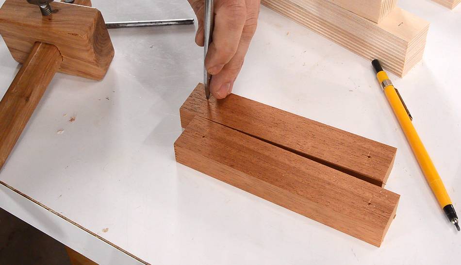
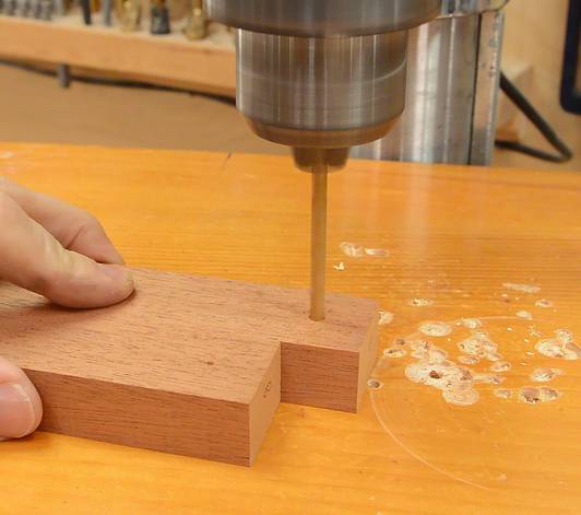
The link that has the operator handle on it is a solid piece of hardwood.
I cut the straight part on it with the table saw, then finished the cut and made
the angle cut on the bandsaw.
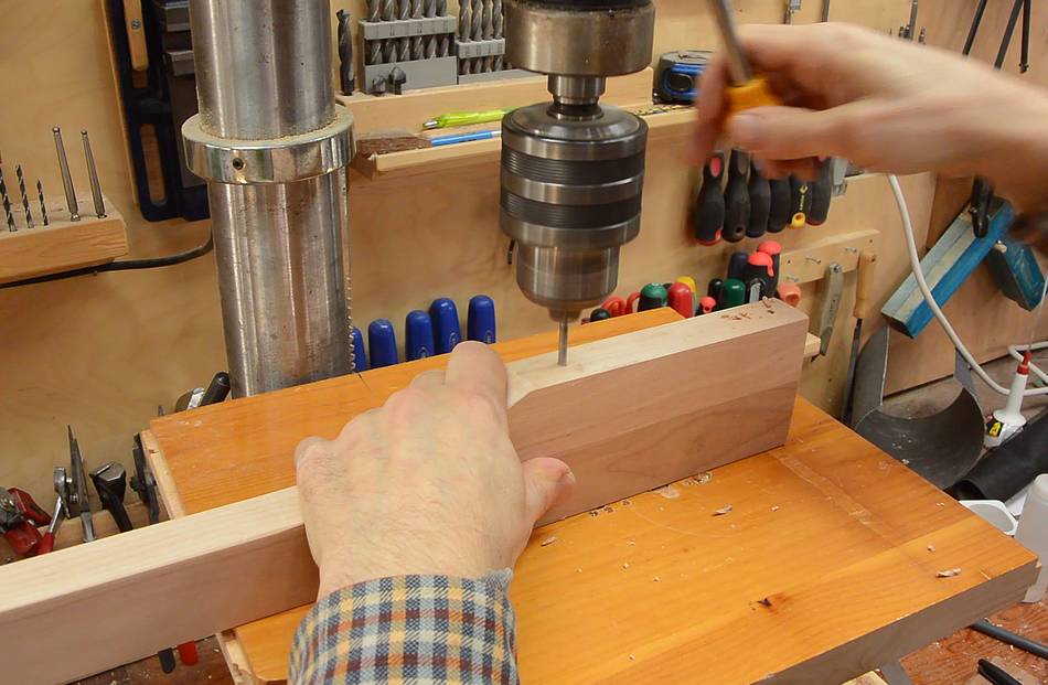
A small drill bit would drift far too much while drilling all the way through
this piece of wood, so I marked the hole locations on both sides, then drilled
in from either side. I drilled quite a bit past the half-way point for the second
hole to get the drill to line up with the first hole.
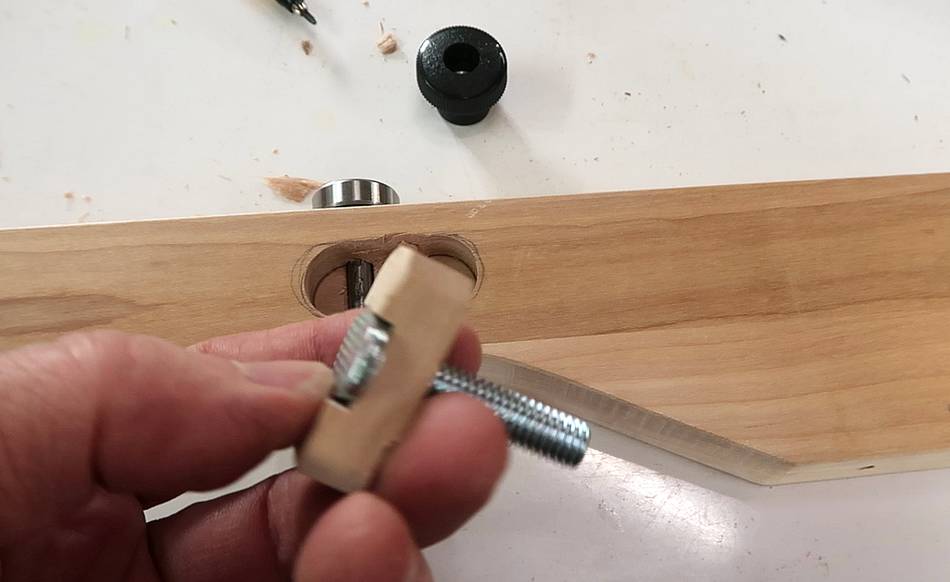
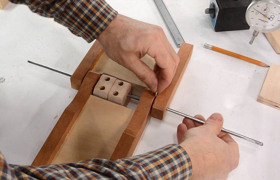
I came up with this clever little block that sits in a hole for where the follower
bearing goes. I'm not sure now whether this was a good idea or not.
(As it turned out later, this was not a good idea. The
simple clamp that I
made for the pantorouter XL is easier to make and works better, and I later re-built
it that way.)
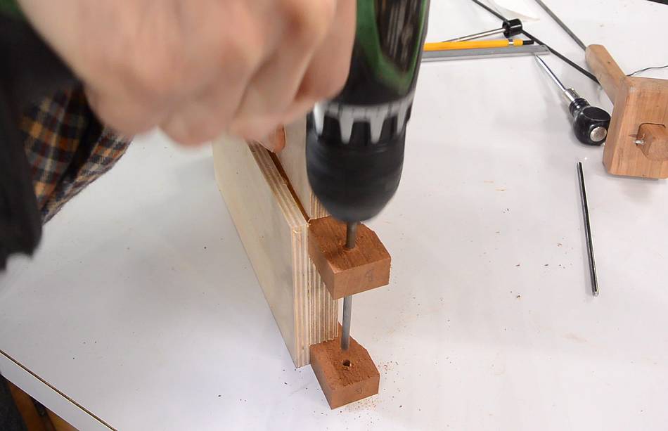
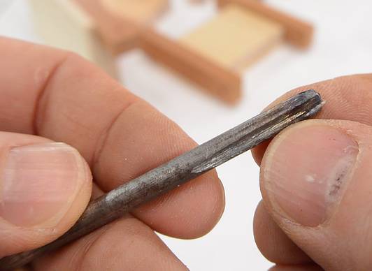
I made a "reamer" out of an extra piece of the shafts I'm using for the pivots
just by grinding a slot into the end of it with an angle grinder. You could also
cut such a slot with a hack saw.
Then used this reamer to expand the holes to make an exact fit. This also allowed me
to ream them out a bit to get the holes pointing at each other.
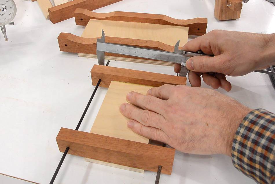
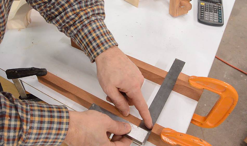
Checking the links for accuracy. The critical aspect is that the shafts
are the right spacing and parallel to each other. Here checking the distance front
and back.
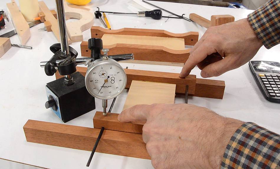
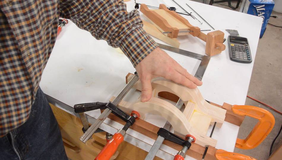
And checking for twist by putting the link on two straight pieces of wood on my flat
workbench top. This link unfortunately rocked back and forth a bit, indicating
it has some twist.
Checking it with a dial indicator, it had about 0.020" of rocking back and forth,
or about 0.5 mm. More than I would like it to have, but I will leave this one as
is and hope the result will be okay.
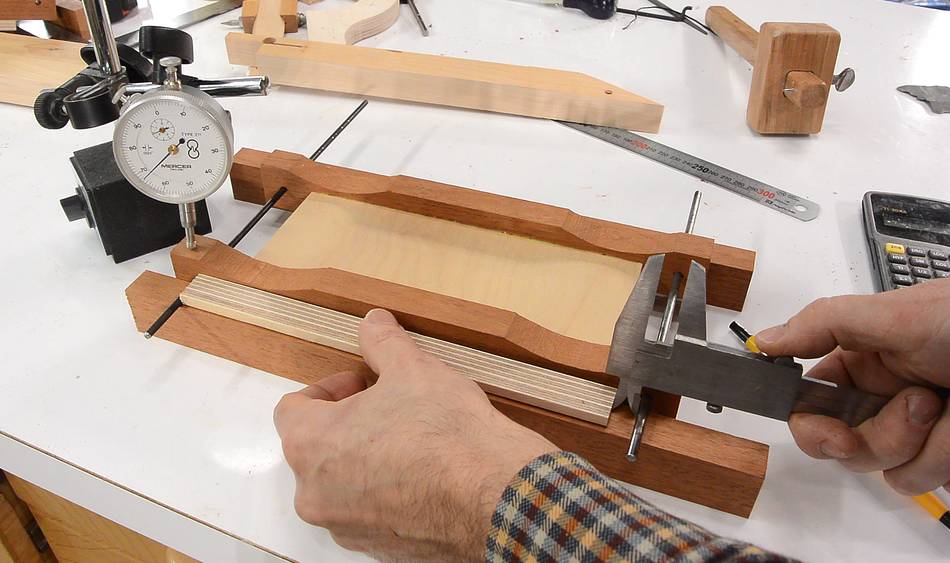
Checking the longer link the same way. I used a piece of wood to extend the
range of my callipers for checking the spacing front and back.
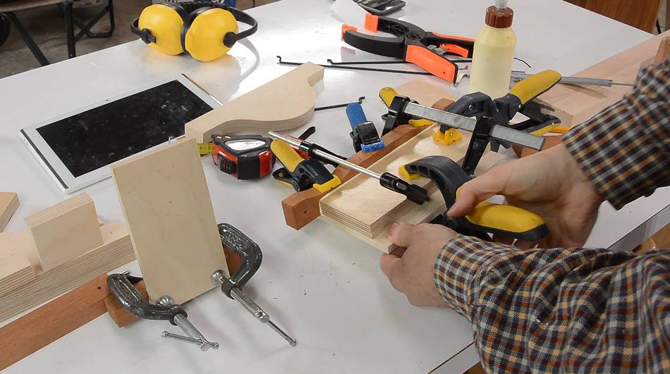
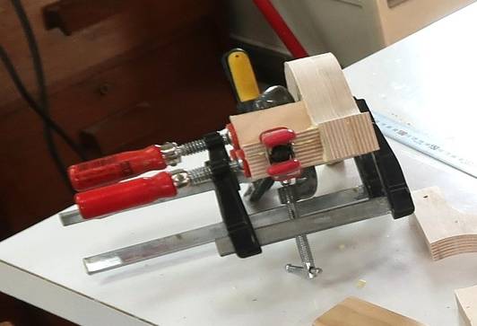
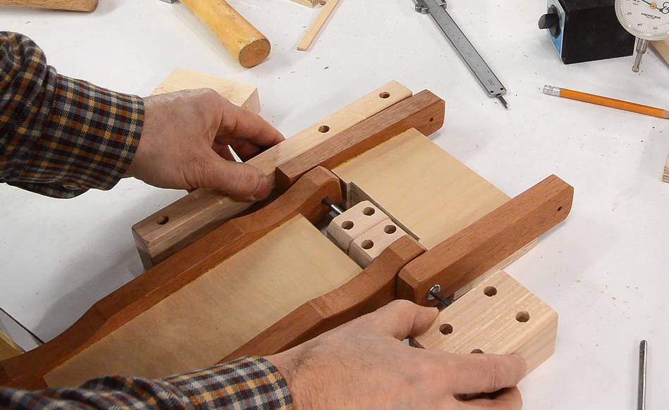
After gluing the back two layers together, I glued the spacer blocks onto the
router mount link (photo at right). After that, I checked how it would line
up with the front link, and in the process discovered that I had a hole on
one end misplaced by more than half a millimeter!
I didn't want to make that same part again, so I decided to try to ream that hole
out a bit towards the side. I drilled a hole in a piece of solid maple, clamped that
to the link part so that the hole in the maple was in the right place, then
reamed the hole out again. It took a few minutes, but I managed to expand the hole
to the side by as much as I needed. I may glue a tiny splint into the rest of the
hole later to close up the slack. Another option would have been to glue a plug
in the hole and re-drill it.
I rigged up a simple "jig" to help ensure the main router link was aligned properly
as I glued it. Just two pieces of wood clamped to the workbench, with stops
on one end that are perpendicular to the strip.
I pressed the router mount down and against the stops on the end while I tightened
the clamp to force it into alignment.
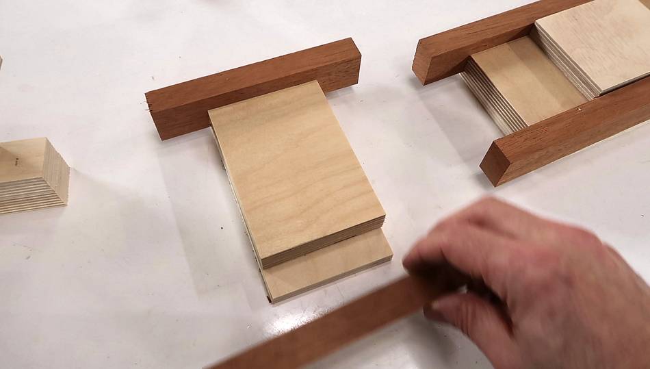
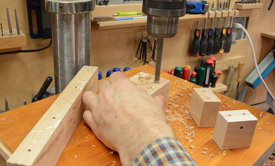
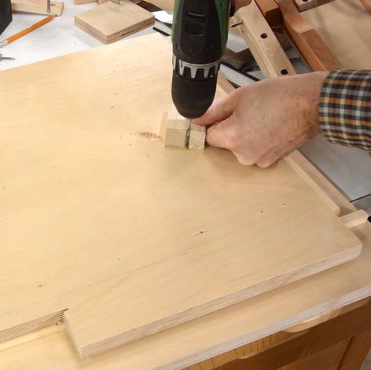
I then made the blocks for mounting the pantograph to the sliding base.
These are more rectangular pieces with holes drilled in them, so again I
didn't take photos of that.
The two smaller blocks (at right) needed a bit cut off the corners to not interfere
with the links, however.
Assembling the two links on the main pivot. There are washers between the pieces
of mahogany. The second of these washers was quite tricky to get into position.
I eventually got it in place by orienting the shaft vertically, then used another washer
to push the washer I needed in place. I then pushed another shorter piece of shaft in from
the other end to capture the washer, then pushed the main shaft through all the way,
pushing the shorter shaft out in the process.
Two more mounts go on either end of the pantograph links, again with washers on
the shaft between the links and the mounts.
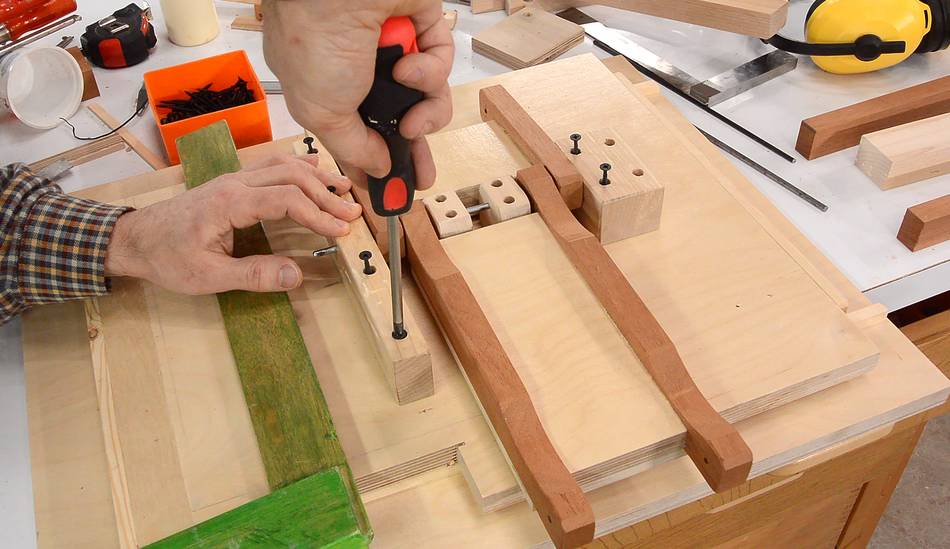
Then carefully measuring where the links need to go. I put screws in the screw holes
and pushed them down into the plywood base to make small divots for where the pilot
holes need to go.
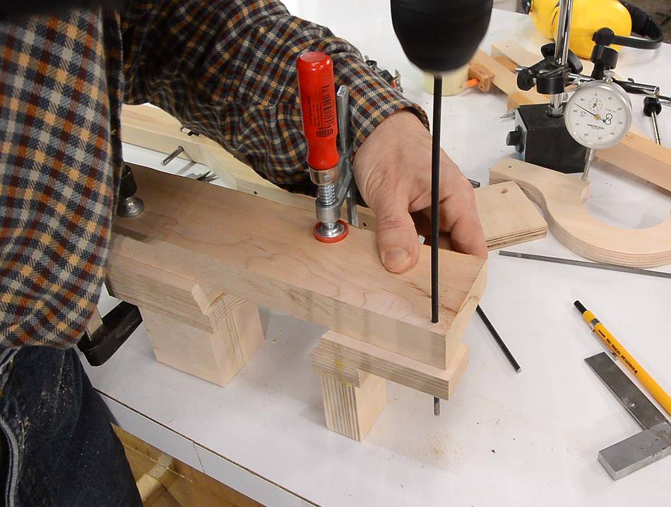
I then used a small block of wood with a notch cut into it to make sure I was drilling
the pilot holes square and also limit how deep I drilled the holes.
Finally, assembling the pantograph. I used a piece of wood to drive the pins
in place. With small inaccuracies in the individual parts, there is a bit of friction
to get some of these pins in.
There is still some work remaining on the pantograph, but I'll work on the template
holder that goes behind the pantograph next.
 Although I include printable 1:1 templates in the plans, I figured
this time I'd just draw the shape from the drawings on my tablet. This was partially
inspired by windows 10 not getting along that well with my printer, and partly to
show that you can build the pantorouter even if you don't have a printer.
Although I include printable 1:1 templates in the plans, I figured
this time I'd just draw the shape from the drawings on my tablet. This was partially
inspired by windows 10 not getting along that well with my printer, and partly to
show that you can build the pantorouter even if you don't have a printer.
 Pantograph for the pantorouter XL
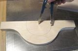 Pantograph for my first pantorouter
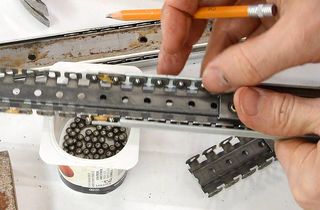 Maing the linear glides for this pantorouter
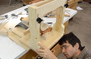 Maing the template holder
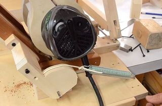 Pantograph spring balance