 The main part of the pantorouter is the pantograph mechanism that
mounts t he router.
I figured I might as well start with the most complicated part of that,
which is the router mount.
The main part of the pantorouter is the pantograph mechanism that
mounts t he router.
I figured I might as well start with the most complicated part of that,
which is the router mount.
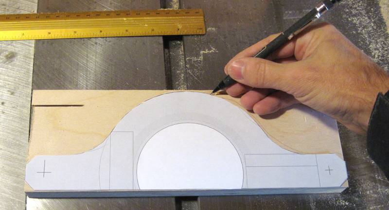
I used a 1:1 printout from my CAD model and traced it onto plywood to get the rough outline.
The router I'm using is one with an 89 mm (3.5") diameter body. These are very common in north america, but less so in other parts of the world. However, the DeWalt D26204 router is suitable, available worldwide, and has been used for the Pantorouter in several machies built by readers. You could also use a smaller palm router
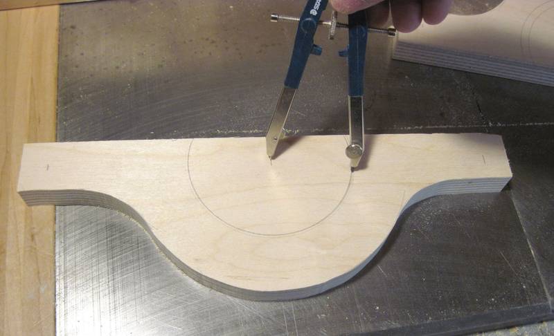 I laid out the relative positions of the router and mounting pins with
a ruler and compass.
Paper templates printed on ink jet printers are surprisingly accurate,
but I printed this template on a laser printer, and my experience is
that laser printers can't be fully trusted to be geometrically accurate.
I laid out the relative positions of the router and mounting pins with
a ruler and compass.
Paper templates printed on ink jet printers are surprisingly accurate,
but I printed this template on a laser printer, and my experience is
that laser printers can't be fully trusted to be geometrically accurate.
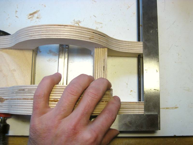 Accuracy is key to getting something like this to work well. I checked
the alignment of the back layer with the front layer using a square, as
I clamped it.
Accuracy is key to getting something like this to work well. I checked
the alignment of the back layer with the front layer using a square, as
I clamped it.
I pressed everything down on my work surface to get all the pieces touching the work surface, then checked the side-to-side alignment with a square.
 This picture shows how I checked the links for twist - easy enough
to do on a flat surface.
This picture shows how I checked the links for twist - easy enough
to do on a flat surface.
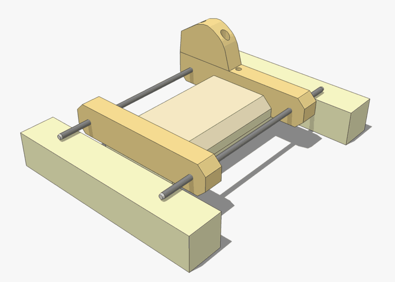
I neglected to take a photo of that, but I used the CAD model from the plans to generate this view.
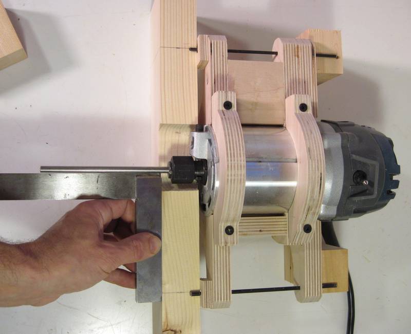 Next I checked that the router's axis is aligned correctly in it's mount.
I'm checking that the router's axis is exactly half way between the two
rods on either side, and that it's parallel to them.
Next I checked that the router's axis is aligned correctly in it's mount.
I'm checking that the router's axis is exactly half way between the two
rods on either side, and that it's parallel to them.
I put a piece of 1/4" rod in the router collet for those checks. I turned the router a few turns by hand to make sure that the rod didn't wobble and make sure it was in straight.
 With all the checks, I found some minor inaccuracies that needed to be corrected.
I had to sand out a little bit of my router mount to get the router in the
right position. I added shims on the opposite side to where I sanded.
With all the checks, I found some minor inaccuracies that needed to be corrected.
I had to sand out a little bit of my router mount to get the router in the
right position. I added shims on the opposite side to where I sanded.
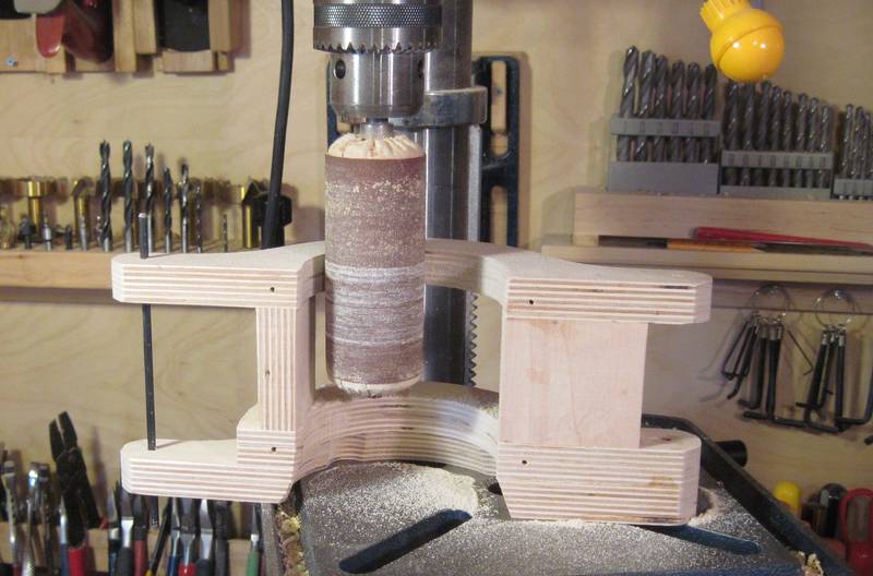
 A more serious problem was that one of my holes was off by a millimeter.
I filled the hole by gluing a stick of wood into it, then re-drilled the new hole
overlapping with the old.
A more serious problem was that one of my holes was off by a millimeter.
I filled the hole by gluing a stick of wood into it, then re-drilled the new hole
overlapping with the old.
Drills have a tendency to drift when they hit existing holes, even filled ones. So I made sure I had everything rigidly clamped down, and pushed the drill bit mostly into the chuck so that there was only about 2 cm of it sticking out. I also brought the table up as close to the chuck as I could so the drill's quill wouldn't need to extend very much. This sufficiently cut down on flex (even with my cheap drill press) that the drill didn't drift.
I have since built another router mount for a palm router on the pantorouter. I got the alignment right on that one on the first try, so no need to re-drill any holes.
 From experimenting with my proof of concept prototype,
I realized that having to always pull up on the handle to counteract
the weight of the router was tiring. So I added some "cams" and springs to
compensate for the weight of the router.
From experimenting with my proof of concept prototype,
I realized that having to always pull up on the handle to counteract
the weight of the router was tiring. So I added some "cams" and springs to
compensate for the weight of the router.
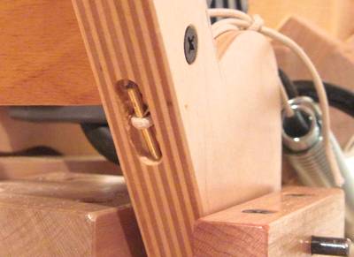 A piece of string wrapped around the cam, and attached
to the spring lifts it up. I worked out the cam's profile so that it balances
the increasing spring force as the spring is stretched with
how the router needs increasing forces as it's tipped off vertical.
I attached the string to the links by looping it around a piece of coat hanger wire
on the other side.
A piece of string wrapped around the cam, and attached
to the spring lifts it up. I worked out the cam's profile so that it balances
the increasing spring force as the spring is stretched with
how the router needs increasing forces as it's tipped off vertical.
I attached the string to the links by looping it around a piece of coat hanger wire
on the other side.
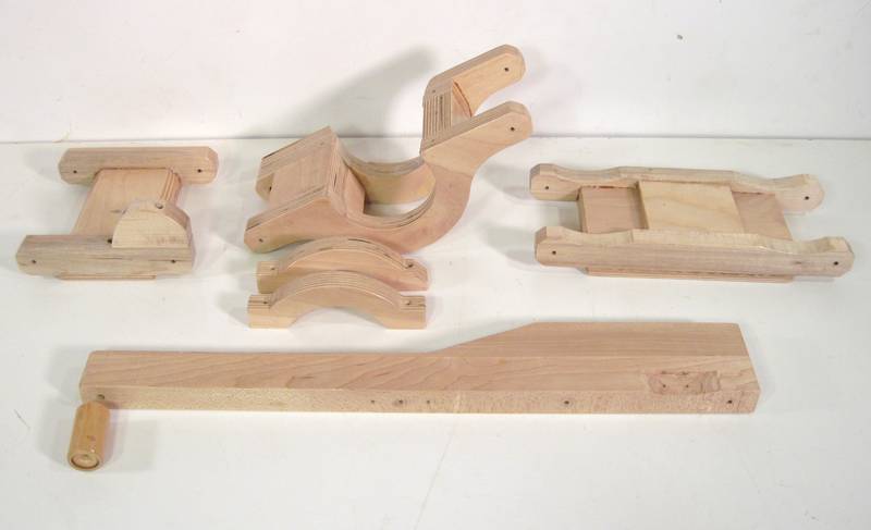 Here's the pieces of the pantograph mechanism. The long piece at the front
is the operating handle, which also forms a link of the pantograph.
Here's the pieces of the pantograph mechanism. The long piece at the front
is the operating handle, which also forms a link of the pantograph.
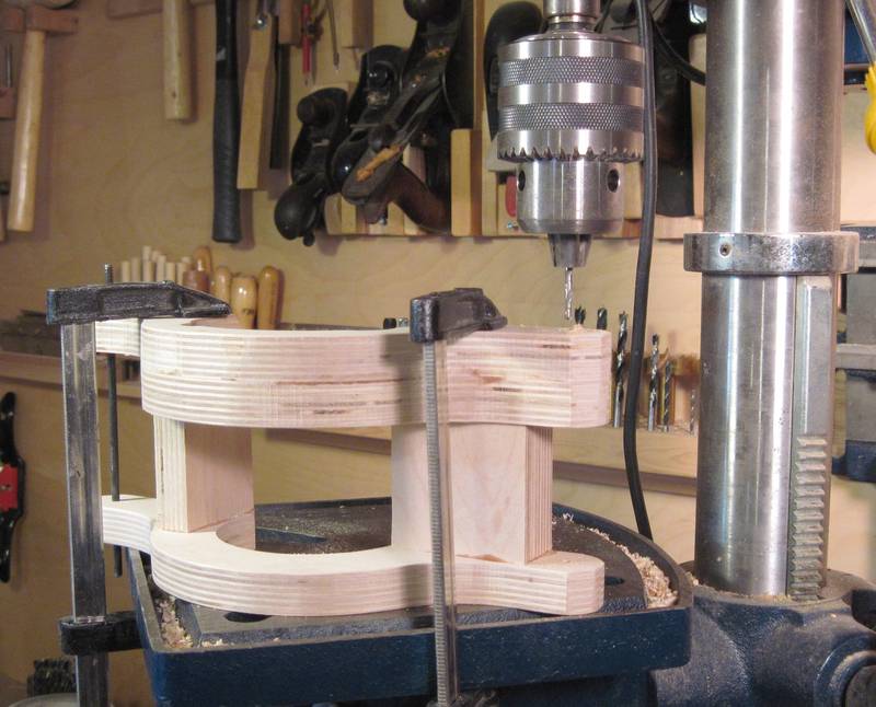
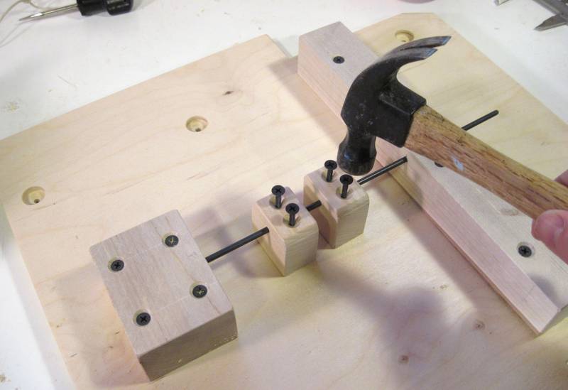 I carefully laid out the position of the support blocks on the base plate.
A useful technique for marking where to drill the screw pilot holes is to
tap the screws so that their points make a divot in the wood.
I carefully laid out the position of the support blocks on the base plate.
A useful technique for marking where to drill the screw pilot holes is to
tap the screws so that their points make a divot in the wood.
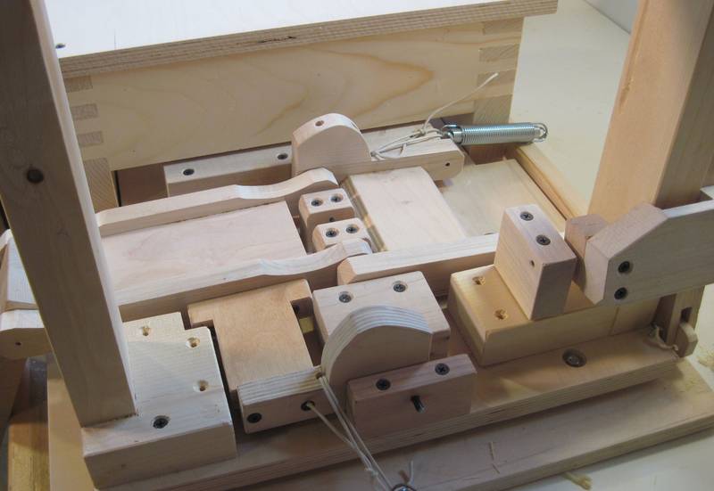 Two of the pantograph links in place. Space is tight around the mechanism,
but I made sure it all fit in my CAD model before I built it.
I have the springs attached to their strings, but the springs aren't in their
proper places in the photo.
Two of the pantograph links in place. Space is tight around the mechanism,
but I made sure it all fit in my CAD model before I built it.
I have the springs attached to their strings, but the springs aren't in their
proper places in the photo.
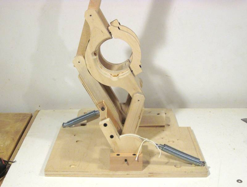 The pantograph on its base, without anything else attached. This was
still trial assembly. On final assembly, I had the base mounted
on its slides with the base below..
The pantograph on its base, without anything else attached. This was
still trial assembly. On final assembly, I had the base mounted
on its slides with the base below..
Without the router weighing the pantograph down, the springs will lift the pantograph roughly straight up.
I experimented with using two springs on each side, one inside the other. I had originally calculated the spring force and cams to compensate for just the weight of the router, but then added the second spring to also compensate for the weight of the wooden mechanism. The two springs overcompensated, so the router always ended up at the top of its range of motion unless I pushed down on the handle. While this was comfortable to operate, it was awkward when mounting templates because the router would always be in the way. So I took the second springs out so that the router normally rests on the bottom.
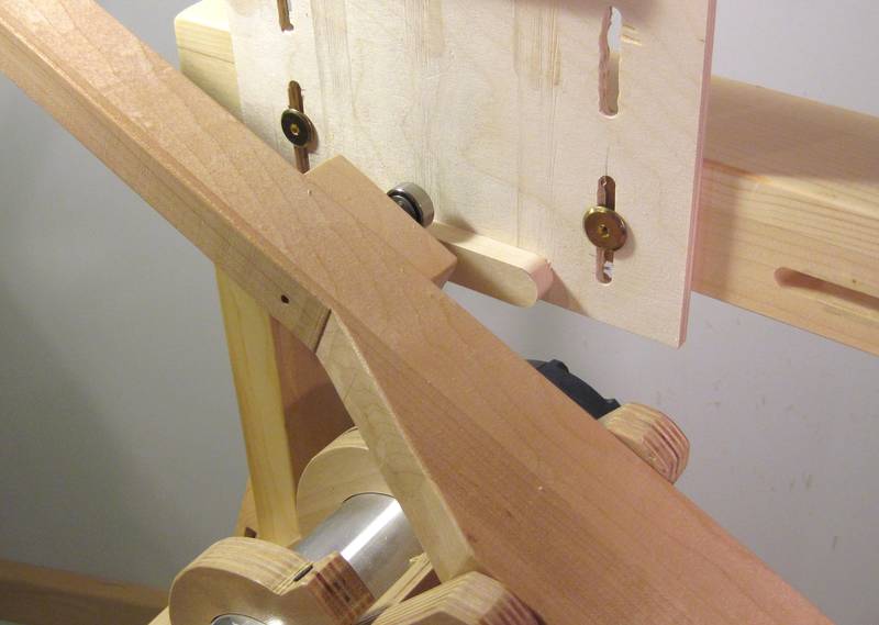 A ball bearing attached to the control lever is used to follow the templates.
Ideally, the ball bearing is twice the diameter of the router bit, so that
the template will be exactly twice the size of the final shape cut by the router.
A ball bearing attached to the control lever is used to follow the templates.
Ideally, the ball bearing is twice the diameter of the router bit, so that
the template will be exactly twice the size of the final shape cut by the router.
But router bits don't always cut to their exact nominal size, and some sizes of ball bearings are hard to get. I was unable to get a 1" outside diameter ball bearing from a local bearing store. It seems precision bearings are mostly in metric.
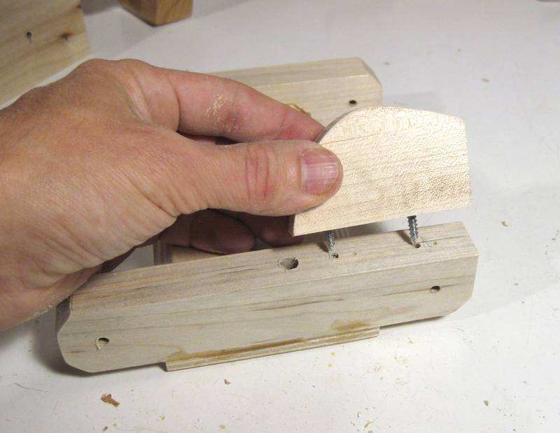
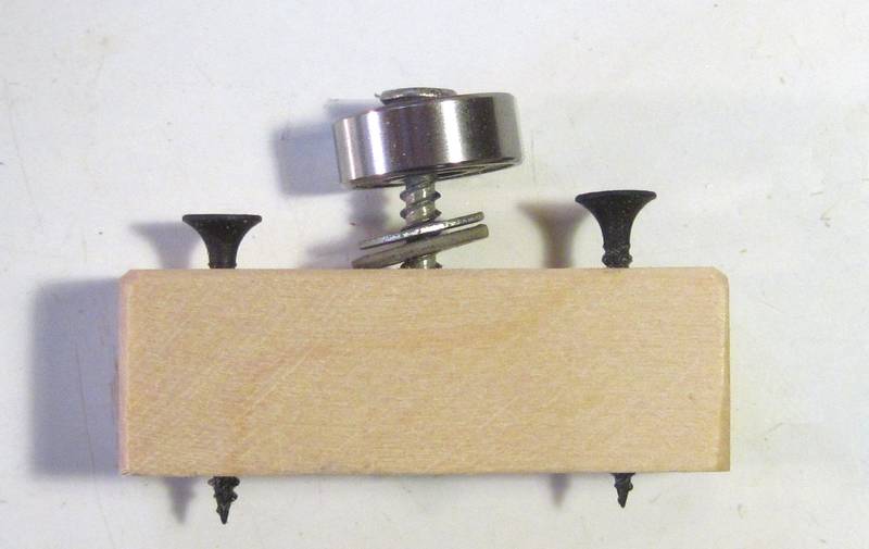 The ball bearing is mounted on a small block of hardwood, which in turn is screwed to the lever.
I found that I needed different sized mounting screws to accommodate different sized bearings.
The mounting screws in turn need different sized holes, so it's best to just leave the ball bearings
mounted to the block and swap out the whole block when changing bearing sizes.
The ball bearing is mounted on a small block of hardwood, which in turn is screwed to the lever.
I found that I needed different sized mounting screws to accommodate different sized bearings.
The mounting screws in turn need different sized holes, so it's best to just leave the ball bearings
mounted to the block and swap out the whole block when changing bearing sizes.
Although this method of mounting the follower bearing is simpler, mounting the follower bearing on the end of a rod is much better, and for my update in 2018, I changed the plans to reflect this change.
 Building a router mount for a palm router
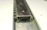 Linear glides from drawer slides
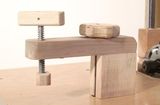 Making the holddown clamp
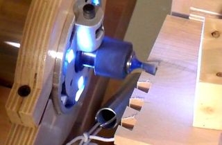 Dovetail joints on the pantorouter
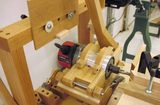 Reader built pantorouter machines
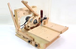 More about the pantorouter
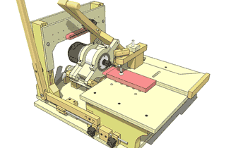 Buy plans for the pantorouter
 Buy a metal pantorouter at pantorouter.com