 This page is about turning over/under, or double tiered style full extension drawer slides into
linear glides for homemade woodworking machines.
This page is about turning over/under, or double tiered style full extension drawer slides into
linear glides for homemade woodworking machines.
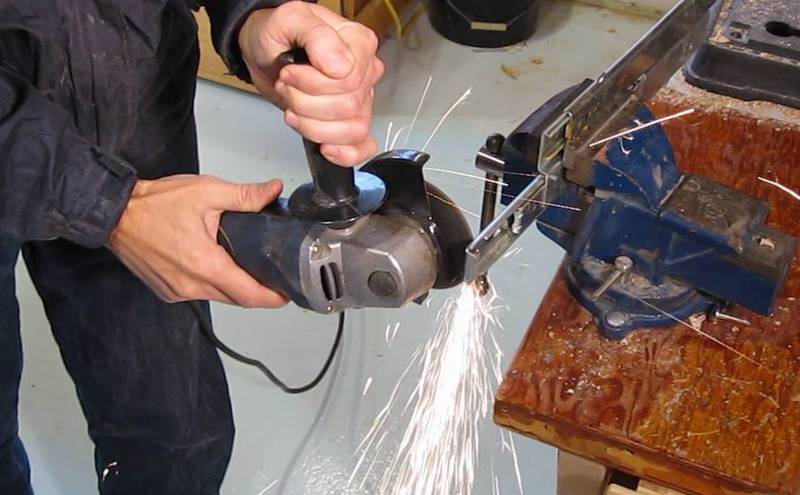
It's a bit of work making the slides suitable for something like a wooden mortising machine but industrial linear ball glides start at prices in the hundreds of dollars each, so it's well worth the trouble.
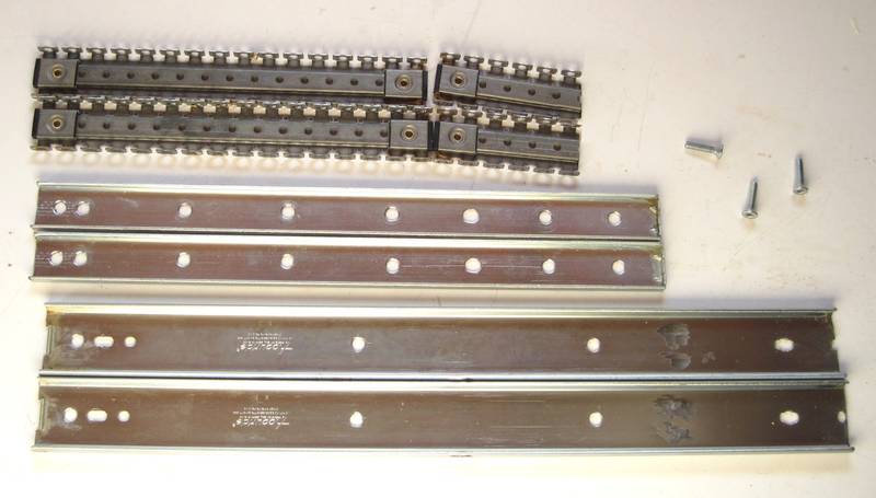
It's important to use over/under style drawer slides. Telescoping full extension drawer glides are becoming more popular today, but I have found that these have too much play. They need to have play in them so as to avoid jamming up if the drawers and their enclosures have a slight bit of mismatch to them. The balls between the innermost and middle layer of telescopic glides have less play, but the middle layer would be difficult to mount, so they aren't as suitable as the older over/under or double tiered style slides. You can still order the old style from Lee Valley Tools, search for "double tiered drawer slides" on their website. Easier to obtain and just as suitable are "keyboard drawer slides", or "center drawer slides".
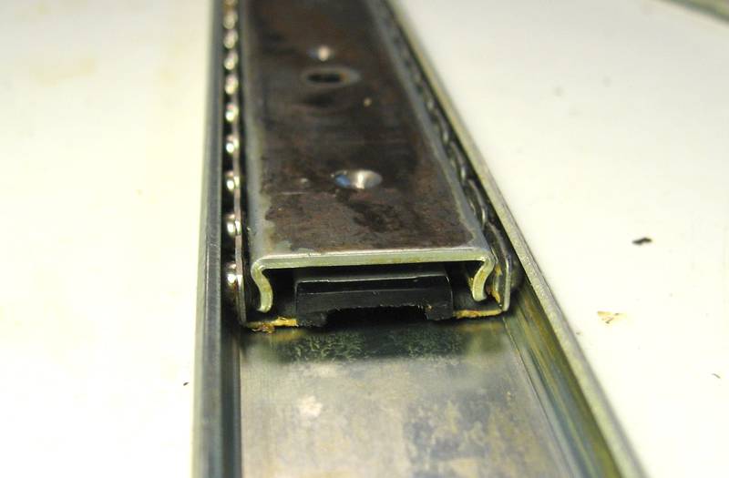
 Check the material thickness of your slides. The good ones are made of sheet metal that is at
least one millimeter thick. If it's less than a millimeter thick, don't use them.
Check the material thickness of your slides. The good ones are made of sheet metal that is at
least one millimeter thick. If it's less than a millimeter thick, don't use them.
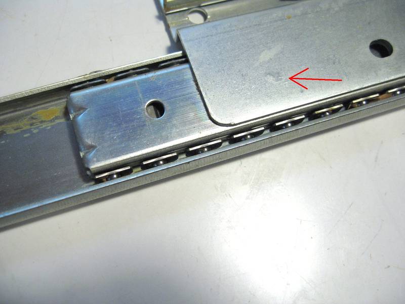
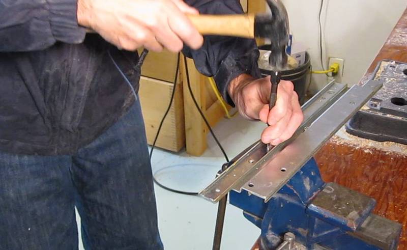
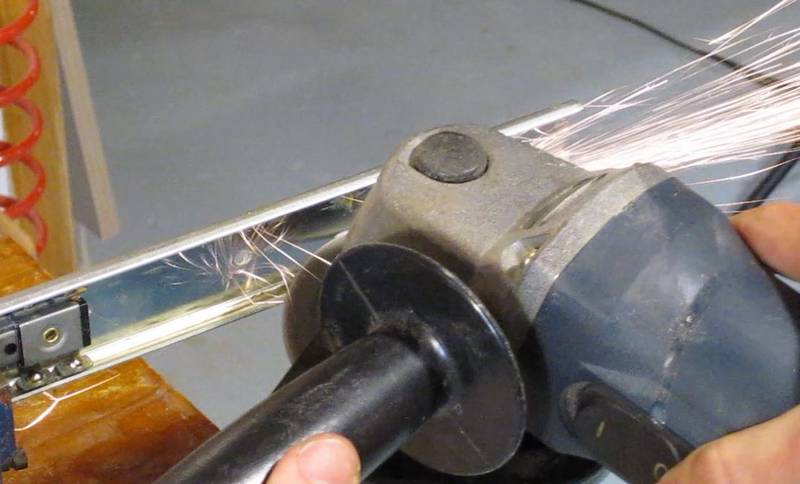
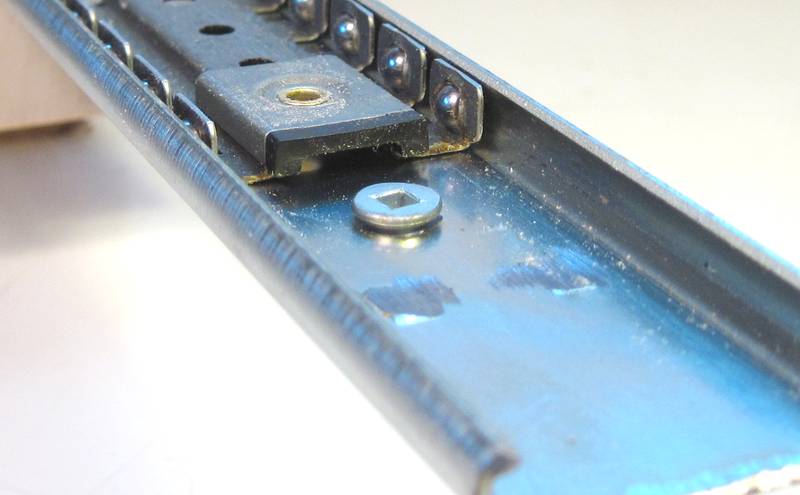
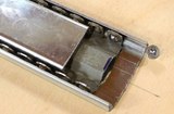
An 'S' profile bracket is spot welded onto the upper and lower rails to connect them together. The arrow in the photo at left points to the spot weld. It really doesn't show up very well from this side. It's much more visible from the other side, but to get at it we have to take the slide apart. If you are using keyboard drawer slides, there are also some spot welds to drill out, but center drawer slides require the least amount of modifications.
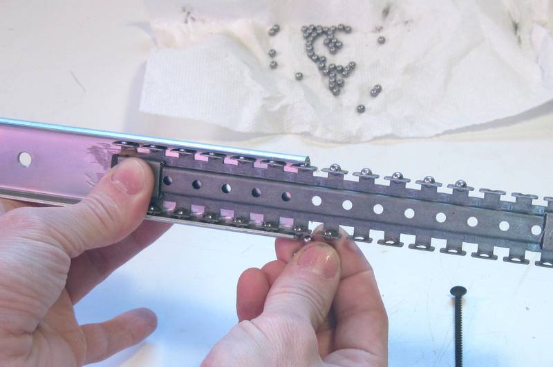
Be careful to capture all the ball bearing balls that will fall out when you slide the slides apart.
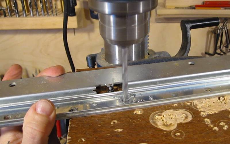
I like to put a drop of oil on the spot where I drill before starting to drill. It helps lubricate the drill a little bit and makes cutting go slightly easier. It also makes smoke if the drill gets too hot. Be very careful when the drill breaks through the material. If you push too hard for the final bit of drilling, the drill may break through, grab the material, and pull it up.
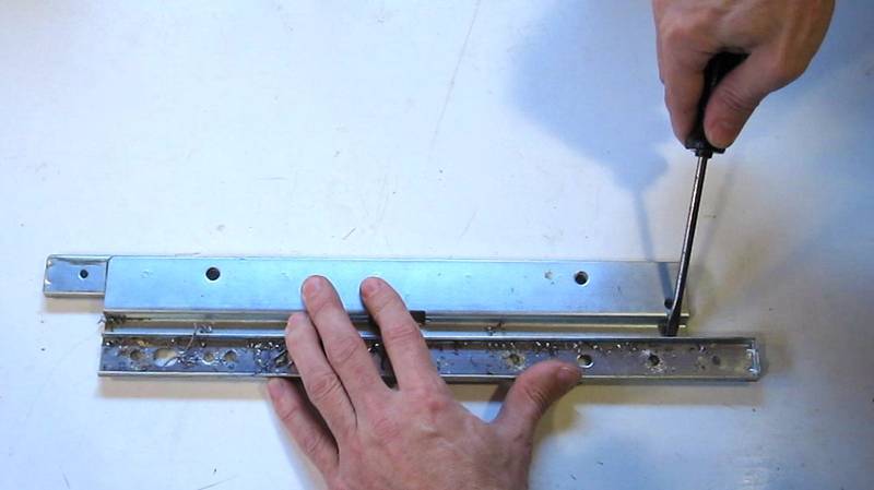
All that metal work with the gliders causes bits of abrasive and metal to get caught in the grease of the slides, so be sure to wipe all the grease off the slides and balls before reassembling anything. Also, don't forget to re-grease the slides before final assembly. I took the shorter of the ball cages and cut them off. I'll use a long plus a short ball cage inside each rail. The more ball cage inside the rail, the better. Seeing that I need less than 10 cm of travel out of my rail, I don't have to worry about my ball cages impeding slide movement.
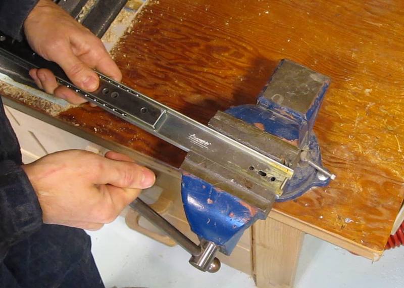
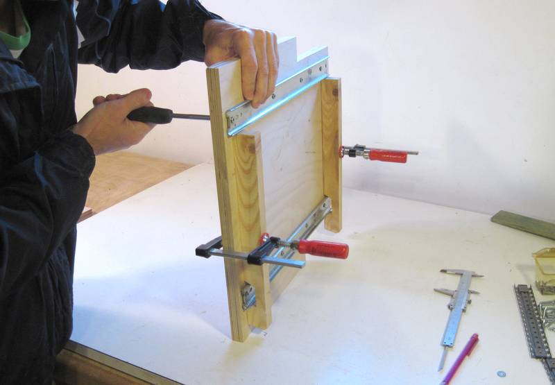
You can tighten up the rails a little bit by squeezing them in a vise. This operation is a little tricky. It's a matter of giving the rail enough of a squeeze to deform just slightly. Do this by squeezing the rail in the vise, then releasing it, and sliding it so that the balls were in the part that was just squeezed to check the tightness. The metal deforms elastically a fair bit before it actually bends, so it's not possible to check for tightness while actually squeezing the rail. It's a matter of squeezing, then releasing and sliding back and forth to check fit, then squeezing again, this time turning the vise slightly further, testing again, and so forth, until the rail has no more play. You may have to do this in several spots along the rail. The video may be helpful to see how it's done.
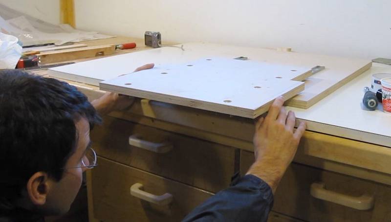
Mounting the rails parallelTo get the spacing just right, take a piece of wood and cut a notch in it After making this cut, cut the piece lengthwise down the middle so that you have two spacers of exactly the same length.
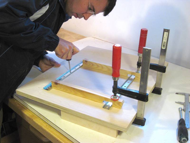 Place one of the rails in the correct position, then clamp the two rails so that
the right edge of each rail hooks onto an edge of the spacer. The spacer should only
touch the right edge of each rail. This ensures that the rails are exactly
the same distance apart, right edge to right edge (and thus also center to center)
Place one of the rails in the correct position, then clamp the two rails so that
the right edge of each rail hooks onto an edge of the spacer. The spacer should only
touch the right edge of each rail. This ensures that the rails are exactly
the same distance apart, right edge to right edge (and thus also center to center)
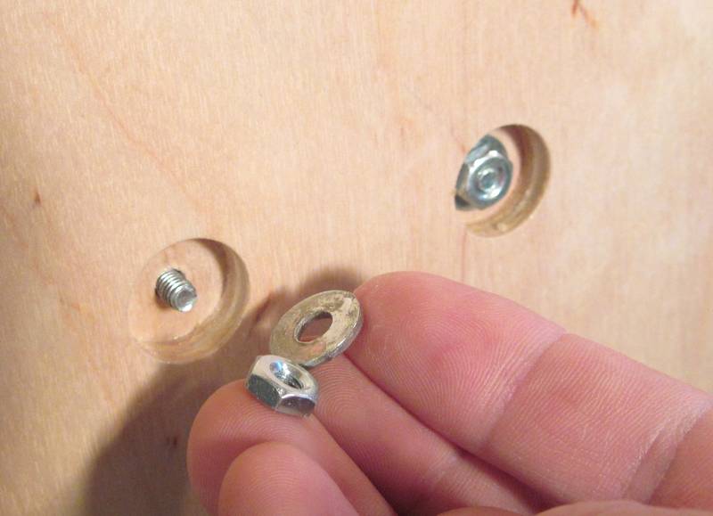
Now mark the position of the screw holes through the holes in your rails.
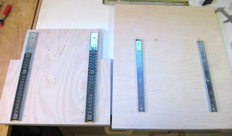
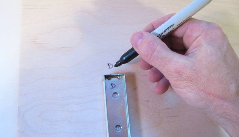 Before removing the rails, label which rail was oriented which way on your wood. Seeing that
some of the mounting holes were hand-drilled, it would be unwise to swap the rails around
after they were used to mark the positions.
Before removing the rails, label which rail was oriented which way on your wood. Seeing that
some of the mounting holes were hand-drilled, it would be unwise to swap the rails around
after they were used to mark the positions.
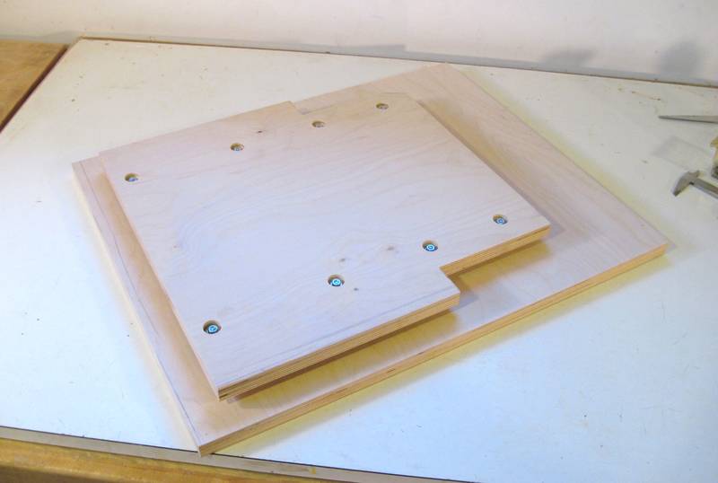
Use the larger C-channel (which forms the outsides of the sliders) for the top side of the sandwich. That way, dust has to go up to get to the balls, as opposed to falling down into the balls of the assembled rail.
With the rails mounted this way with machine screws, it's possible to tighten the screws after the rails are slid together.
Be sure to insert the mounting screws in the rail before covering them up with the ball cages, or you will have to take it all apart again to get those screws in. You'll notice that the mounting holes are not in place in the photo - and I had to take it apart again to get them in after I took that photo!
Beyond the first few centimeters, it will take a firm push to get the sliders together. This is because the ball cages will have bottomed out against the rearmost stops in the top C channels. Once this happens, the balls can't roll any further, and it's necessary to overcome their friction to slide the pieces all the way together. But they should roll back and forth relatively easily after it's been fully slid together.
I used drawer slides as linear glides on my slot mortising machine as well as my new invention that I call the pantorouter
See also:
More about homemade woodworking machines
on my woodworking website.
|
 Linear glides for the
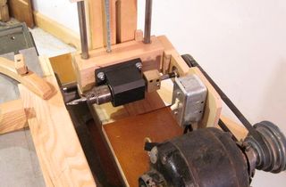 More homemade
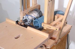 slot mortising machine
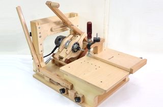 The pantorouter
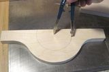 Building the pantorouter