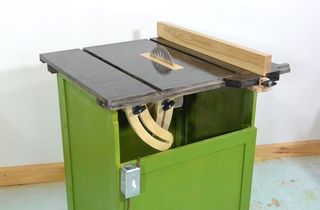
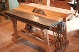
 My homemade table saw is 600 mm wide and 600 mm deep.
The saw's frame is made of 30 mm thick birch plywood. It's on
wheels so it's easy to move. I can push it under my workbench.
My homemade table saw is 600 mm wide and 600 mm deep.
The saw's frame is made of 30 mm thick birch plywood. It's on
wheels so it's easy to move. I can push it under my workbench.
My homemade table saw is 600 mm wide and 600 mm deep.
The saw's frame is made of 30 mm thick birch plywood. It's on
wheels so it's easy to move. I can push it under my workbench.
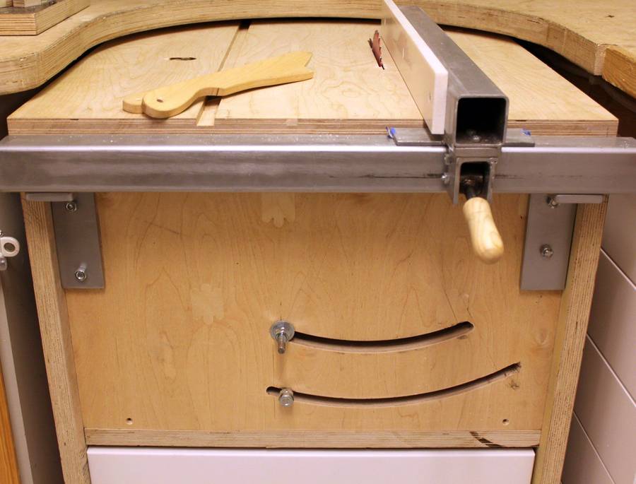
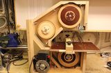
The rip fence is made of 50 mm steel tubing with the sliding surface made of Corian.
The table has a miter slot for accessories like cross cutting sleds.
The blade can be raised and lowered by turning a screw on the front. I use a cordless drill to raise and lower the blade.
Tilting of the saw is locked with the screw in the lower curved slot. There is no handle. I usually lift up the top to tilt the saw. The blade must be fully lowered when opening or closing the saw when it's tilted!
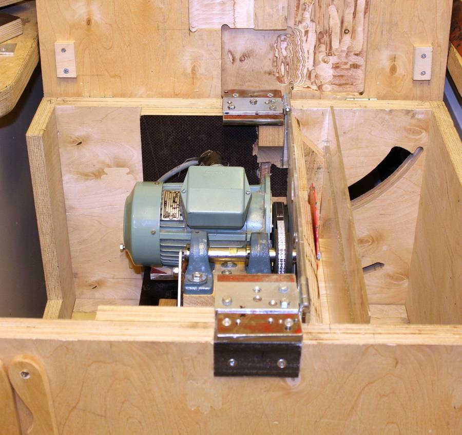
 The arbour and motor are installed on a U-shaped cradle. The whole cradle
tilts to set different blade angles.
The arbour and motor are installed on a U-shaped cradle. The whole cradle
tilts to set different blade angles.
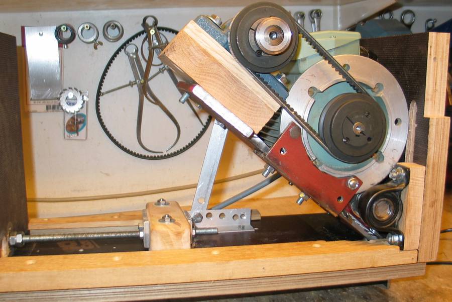
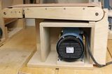
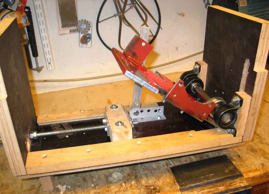
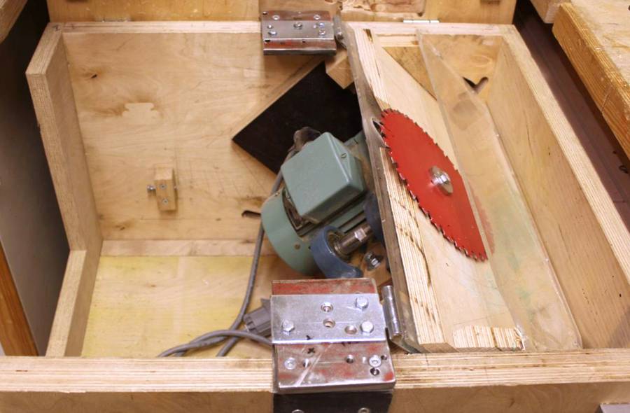
The plate that mounts the motor and arbour can be tilted around a shaft with two pairs of bearings. The plate (red) is made of 10 mm thick steel. The arbour bearings are installed on a wooden block to raise them up further to get the arbour closer to the table. The motor is a 3-phase motor driven with an inverter.
A sliding block under the motor is moved by the depth adjustment screw. This tilts the motor assembly up and down to adjust the depth of cut.
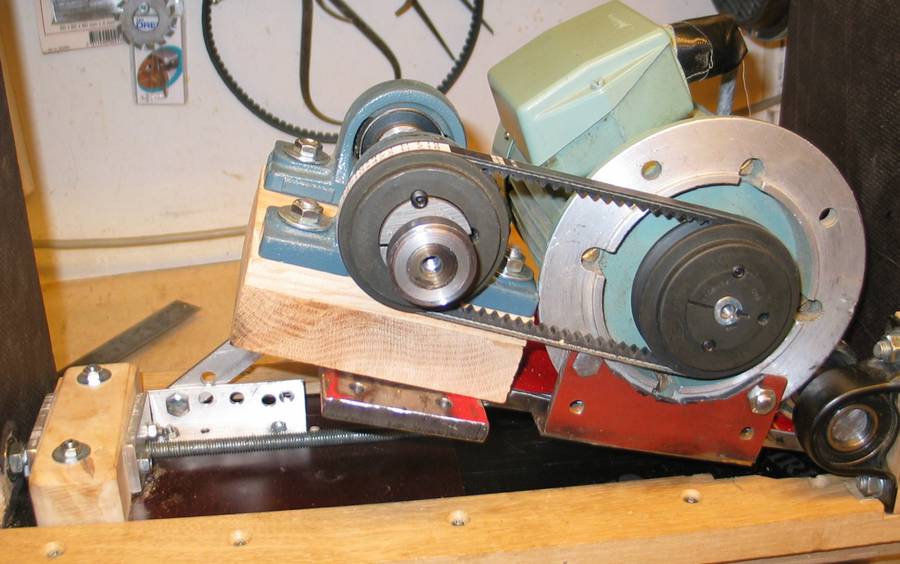 Here the saw is in its down position. The spindle is made from a 20 mm
shaft, a flange is welded and turned to the end, the blade is locked
onto it with a screw.
Here the saw is in its down position. The spindle is made from a 20 mm
shaft, a flange is welded and turned to the end, the blade is locked
onto it with a screw.
The arbour is perhaps the most important component of such saws. It's made from a 20 mm steel rod. I have a very good friend who has a metal lathe, and it was made by him. We work together often, I can help him with design, and another friend of ours has a good garage for welding etc... But any small machine shop can help, it takes only a short time to turn, weld and turn.
I used 20 mm rod because it fits right in the cheap bearings, there is
no need to machine the main shaft.
I can buy this rod locally in short lengths. The bearings
have locking screws to clamp to the shaft.
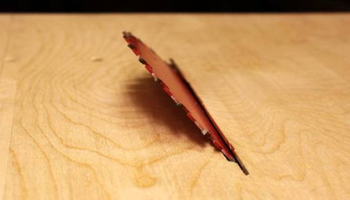
 A 40 mm steel disk with a 20 mm hole is welded on
the end of the shaft Then it is turned on metal lathe on all surfaces. A recess
of 30 mm is turned to fit the blade (the hole on blade is 30 mm) to a
depth a little less than the blade is thick. Then a 7 mm hole is drilled
in the end of the shaft (on the lathe) and a M8 thread is tapped.
A 40 mm steel disk with a 20 mm hole is welded on
the end of the shaft Then it is turned on metal lathe on all surfaces. A recess
of 30 mm is turned to fit the blade (the hole on blade is 30 mm) to a
depth a little less than the blade is thick. Then a 7 mm hole is drilled
in the end of the shaft (on the lathe) and a M8 thread is tapped.
A skilled machinist such as my friend ensures that the blade sits exactly and runs true.
Then we made a small disk of 35 mm diameter with an 8 mm hole. This disk locks the blade onto the arbour with a screw.
It is important keep in mind which direction the arbour turns. In my case it rotates counter clockwise as seen from the blade end. The screw has right hand thread, so the rotation of the arbour will tighten the screw. My saw can be tilted to the left. For right tilting saws, the blade attaches on the other side of the arbour, and it turns clockwise seen from that side. Counter clockwise screws or nuts are used for right-tilting saws.
My motor is installed so that the belt is just behind the blade. I get more room for tilting with this design. The belt pulleys are standard wheels with a tapered collet to lock on the shaft. They are surprisingly cheap.
When I got my arbour installed I fine tuned it exactly so that the blade is parallel to the miter slot and perpendicular to the table top.
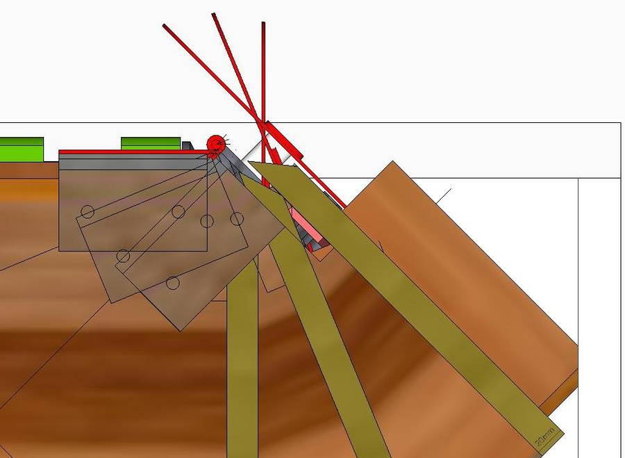
Most saws use trunnions for the blade tilt, but these are difficult
to make, so I used hinges instead.
I played with a computer to study this blade tilting question and found a combination of hinge position and how far the blade should be from the hinge pivot.
The slot for the blade is 6.2 mm wide and accommodates all blade tilt angles.
 Thick steel plates are screwed to the frame, and the hinges are mounted
to these plates.
Thick steel plates are screwed to the frame, and the hinges are mounted
to these plates.
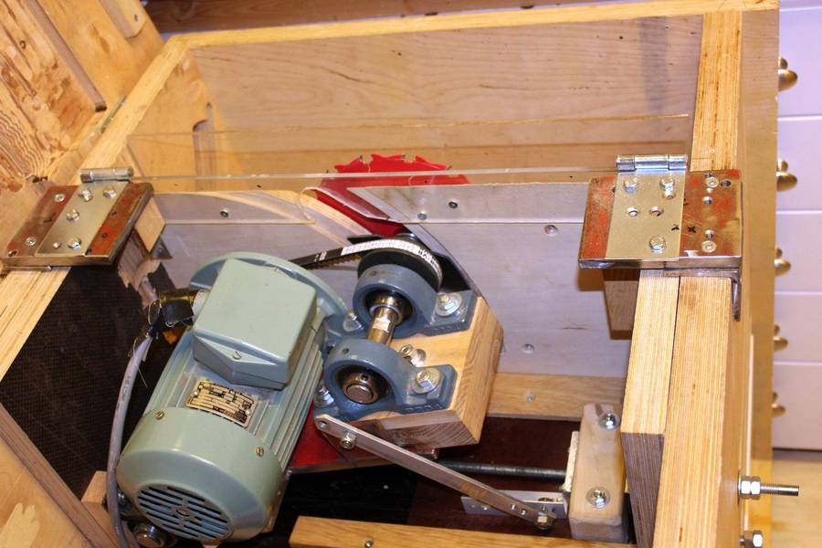
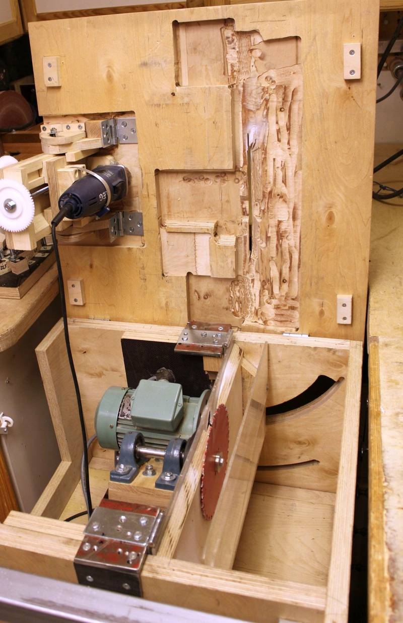 The table top is hinged on the back. I had to route some recesses to
allow for the maximum cutting height.
The table top is hinged on the back. I had to route some recesses to
allow for the maximum cutting height.
My tilting router lift is also installed on the table top.
 For sawdust removal I made a hood of polycarbonate. This connects to my
vacuum system from behind the saw. It captures dust better than
my friend's expensive saw.
For sawdust removal I made a hood of polycarbonate. This connects to my
vacuum system from behind the saw. It captures dust better than
my friend's expensive saw.
Pekka Svinhufvud, Finland
You can also download Pekka's table saw SketchUp CAD model.
Please note that this CAD model was used by Pekka to work out the geometry.
It is not a complete plan with instructions.
 Pekka's three wheeled
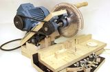 Pekka's homemade
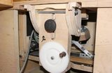 Pekka's tilting router lift
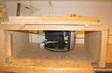 Pekka's first homemade
 Dad's homemade
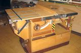 Hector's homemade tablesaw
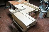 Lucas Contreras's homemade tablesaw
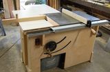 John Heisz's homemade tablesaw
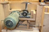 Changes to this table saw