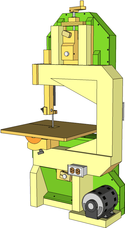
Homemade bandsaw (version 2) build
This project started when people started asking me about plans for my original bandsaw (version 1). I didn't want to give people plans for that one, because I already had ideas for how to build an even better one.
 This second bandsaw is a 16" bandsaw. I chose that size because that's the largest I could
go while still using a 105" blade. 105" blades are used by 14" bandsaws with riser blocks, so
that length is very commonly available and in stock at most woodworking stores.
This second bandsaw is a 16" bandsaw. I chose that size because that's the largest I could
go while still using a 105" blade. 105" blades are used by 14" bandsaws with riser blocks, so
that length is very commonly available and in stock at most woodworking stores.
I had been thinking about making a C-shaped wooden beam for the frame of my second bandsaw. My first thought was to join some pieces of beam together with my screw advance box joint jig, but that would make it necessary for people to build that jig before building the bandsaw. My next idea was to form the beam by laminating individual boards together. That way, I could overlap them at the corners and joints, making for a very rigid frame.
You can click on this image, or any other image in this article to get a larger view.
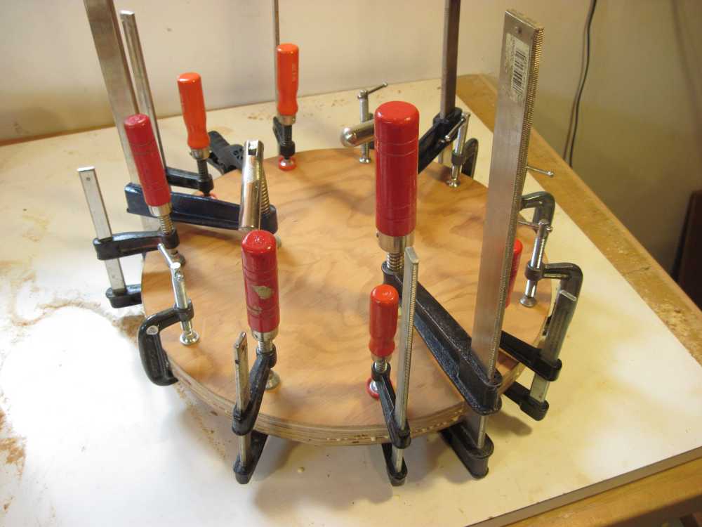
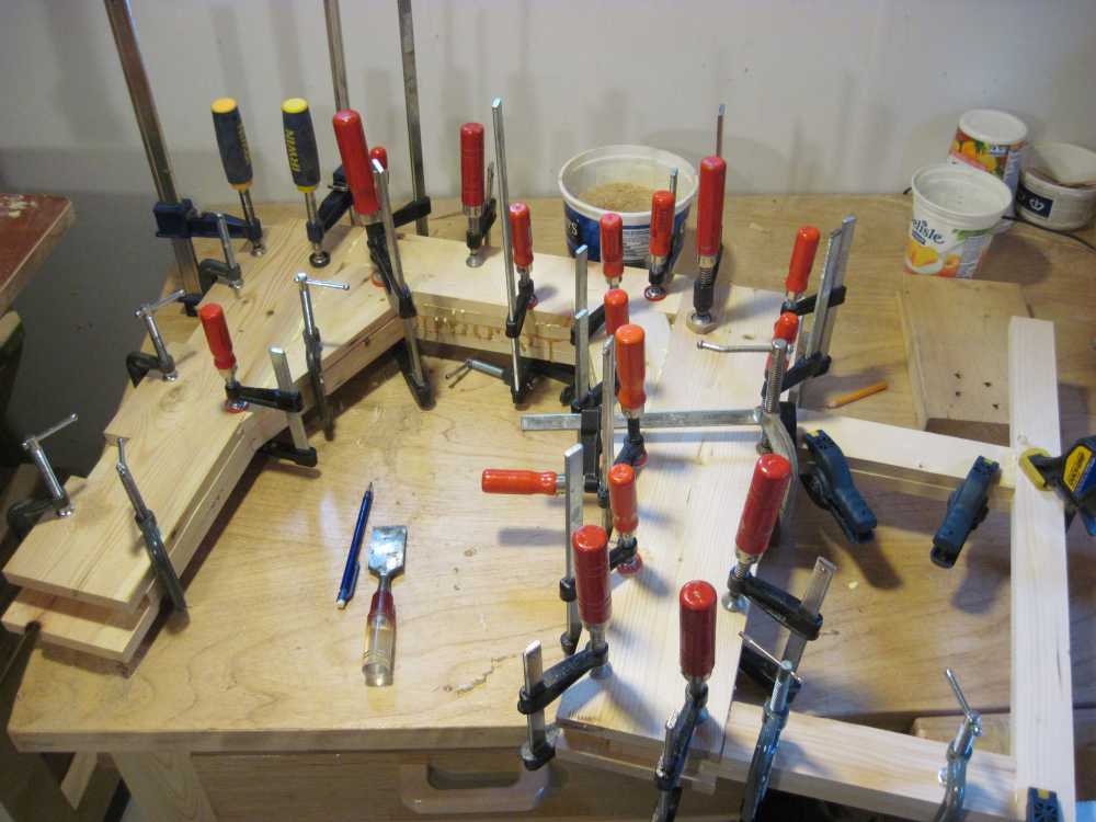 I glued the frame up one layer at a time, letting the glue dry before adding
the next one. That way, I only had to worry about lining up one layer at a time.
I glued the frame up one layer at a time, letting the glue dry before adding
the next one. That way, I only had to worry about lining up one layer at a time.
I ended up using all of my small clamps every time I glued up a layer. Building up the frame extended over the course of a day and a half, as I'd always go and do something else between layers.
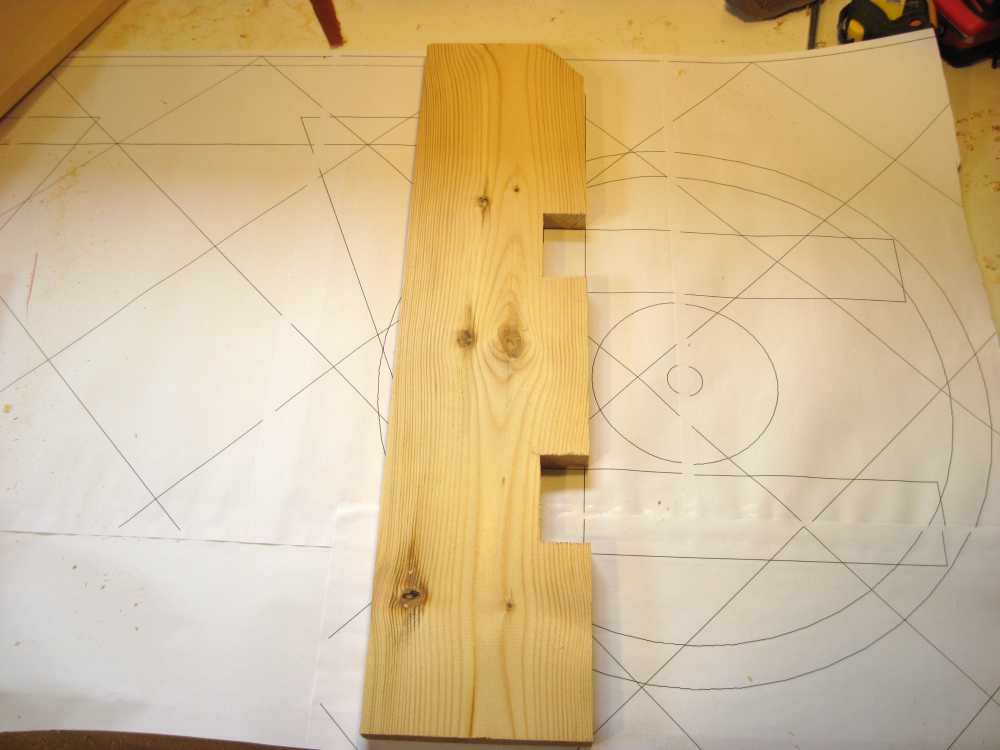 I made a 1:1 scale printout of the frame from my plan by printing it as multiple sheets
of paper and then gluing them together. I added a diagonal grid to help line up my sheets of paper.
I discovered that the diagonal grid really helped line up multiple sheets with my
gear template generator. I segmented this drawing into sheets manually, but later wrote
a program, BigPrint to make it easier to make large printouts like that.
I made a 1:1 scale printout of the frame from my plan by printing it as multiple sheets
of paper and then gluing them together. I added a diagonal grid to help line up my sheets of paper.
I discovered that the diagonal grid really helped line up multiple sheets with my
gear template generator. I segmented this drawing into sheets manually, but later wrote
a program, BigPrint to make it easier to make large printouts like that.
The 1:1 printout came in very handy for checking the dimensions of the pieces I cut - it was just a matter of laying them on the sheet.
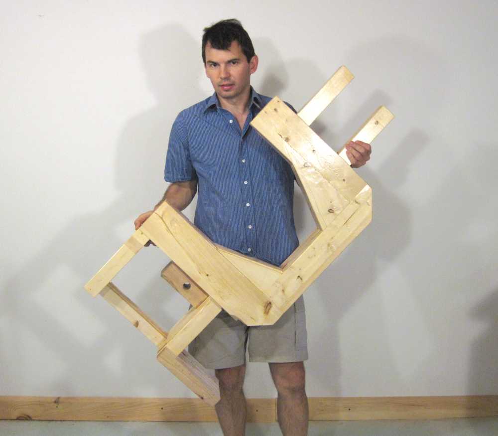 The completed frame is quite light, under 30 pounds (15 kg) in weight, which makes the
bandsaw easy to move.
When I measured how much the fame flexed from tensioning the blade, I found that it was stiffer
than the frame on my cast iron bandsaw.
The completed frame is quite light, under 30 pounds (15 kg) in weight, which makes the
bandsaw easy to move.
When I measured how much the fame flexed from tensioning the blade, I found that it was stiffer
than the frame on my cast iron bandsaw.
This may seem a little surprising, but consider the following figures I gathered from the internet:
| Material | Young's modulus |
|---|---|
| Steel | 200 GPa |
| Cast iron | 80 GPa |
| Pine | 9 GPa in the grain direction |
Young's modulus is a measure of stiffness for a material. The figures for cast iron can vary, and for wood they can vary a lot. Overall though, steel is 22 times stiffer than wood. But cast iron is only nine times stiffer than wood. So a member with nine times the cross-sectional area of cast iron will be as stiff. Spreading the cross sectional area over a wider area also helps, and my wooden beam is a fair bit wider.
Wheel and wheel mounts
 I was pretty sure the nice birch plywood would do for wheels, but I wanted to see how cheaply
it was possible to build a bandsaw. I had some scavenged plywood that was 12 mm thick. I used
two layers of 12 mm, and another layer of 5 mm in between.
This plywood was ordinary plywood, although a slightly better grade
than the packing crate plywood I tried for my initial bandsaw wheel
experiments on my first bandsaw.
I was pretty sure the nice birch plywood would do for wheels, but I wanted to see how cheaply
it was possible to build a bandsaw. I had some scavenged plywood that was 12 mm thick. I used
two layers of 12 mm, and another layer of 5 mm in between.
This plywood was ordinary plywood, although a slightly better grade
than the packing crate plywood I tried for my initial bandsaw wheel
experiments on my first bandsaw.
I used lots of clamps to glue it up. I wanted to be sure I had a good solid glue joint, especially around the edges of the wheels.
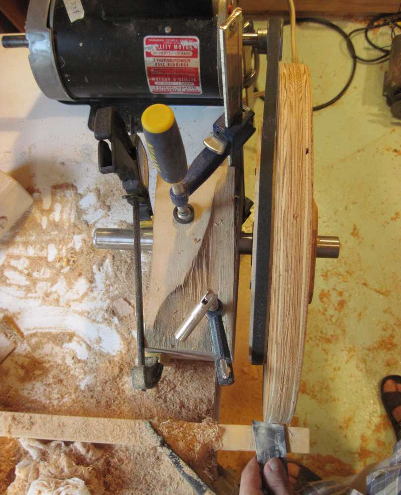 I shaped the rims of the wheels by using the wheels like a lathe.
With the wheel turning on its own bearings, any eccentricity I had with how I mounted them got cut away as I turned the wheel down to its final size.
I did encounter a few voids in the plywood that I had to fill, but I didn't bother filling small voids near the edges. But the middle of the wheel, where the blade normally runs, has to be solid.
I spun up the wheels using a temporary pulley that I screwed to the side of the wheels.
This allowed me to turn both the top and bottom wheels, as well as the main drive pulley
for the bottom wheel. I made the temporary pulley on the table saw, similar to how I made the one for my
other bandsaw
It was at about this stage of progress that I shot my messy workshop video, so you can see pieces of the bandsaw around my shop in the video.
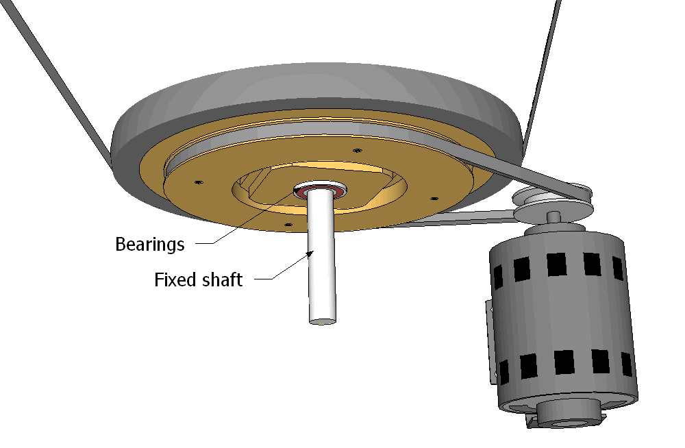 The bottom wheel in my new design spins on a fixed shaft, much like the top wheel does.
A drive pulley is screwed directly to the back of the bottom wheel.
The bottom wheel in my new design spins on a fixed shaft, much like the top wheel does.
A drive pulley is screwed directly to the back of the bottom wheel.
The advantage to this approach is that there is no need to couple wheels and pulleys to the shaft. The other advantage is that the force from the blade tension is divided between two bearings.
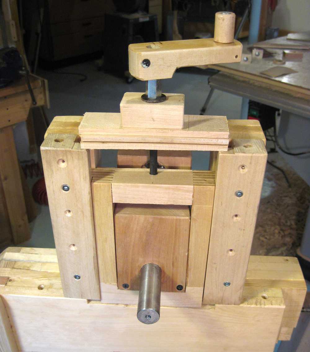 This is the top wheel mount, as seen from the front.
The "tension spring" consists of three thin strips of wood across the top of the frame.
These are meant to bend and act as a spring as tension is increased.
This is the top wheel mount, as seen from the front.
The "tension spring" consists of three thin strips of wood across the top of the frame.
These are meant to bend and act as a spring as tension is increased.
I opted for a simple crank for the tensioning mechanism on this saw. The shape of the frame would have made the lever and ratcheting mechanism that I used on my other bandsaw awkward. I also wanted to keep this bandsaw simple and easy to build. The crank makes it really easy to tension up the bandsaw - I can turn it from no tension to full tension in about three seconds.
Blade guides
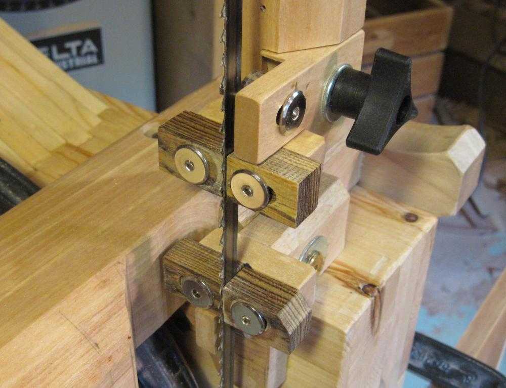
I was originally going to use Lignum Vitae, the hardest of the hardwoods, for the guide blocks. But then I went through my box of exotic off cuts that I bought for this article and tried rubbing each one on my cast iron table saw table to see how slippery they were. The bocote slid the easiest, so I used that.
But you don't need to get bocote. Any hardwood will do, the heavier the better. I'm still using the original oil soaked maple guide blocks on my other bandsaw.
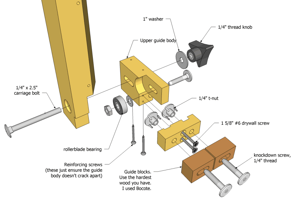 This drawing shows how the blade guides go together. The top and bottom blade guides
are nearly identical in design.
This drawing shows how the blade guides go together. The top and bottom blade guides
are nearly identical in design.
You can click on this drawing, or any of the other pictures in this article for a larger view.
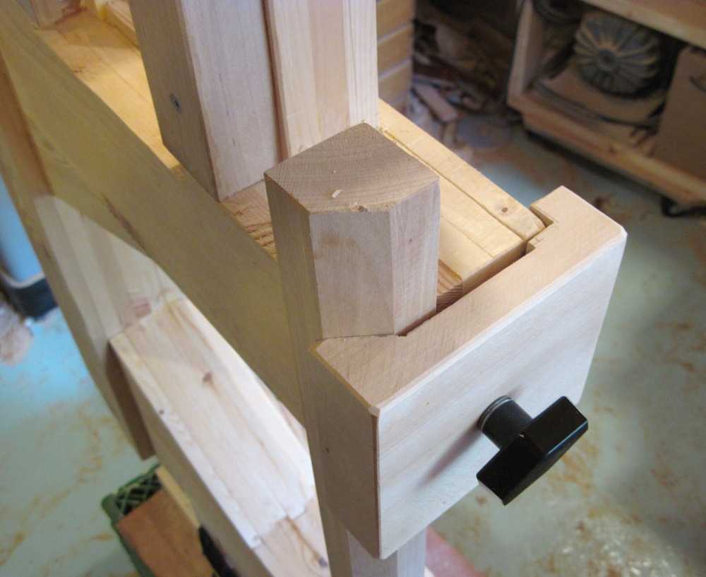 The guide bar is pressed against a notch in the frame. I put a bevel on it where it clamps
on so that it gets pressed into the corner, which rigidly holds it in place.
The guide bar is pressed against a notch in the frame. I put a bevel on it where it clamps
on so that it gets pressed into the corner, which rigidly holds it in place.
The guard needs to be able to fit around the top wheel, yet also slide into the top wheel enclosure.
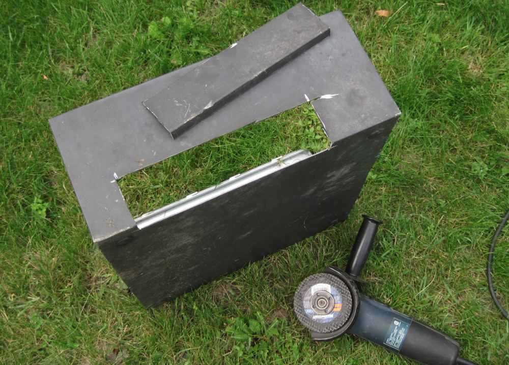 The best source of sheet metal I could think of was to cut it out of an old PC case with an angle
grinder. I cut the piece off the corner, so I already had one bend in the piece. I then used my vise
as a sort of "metal brake" to make the second right angle bend.
The best source of sheet metal I could think of was to cut it out of an old PC case with an angle
grinder. I cut the piece off the corner, so I already had one bend in the piece. I then used my vise
as a sort of "metal brake" to make the second right angle bend.
On to part 2: Trunions, table, and enclosure