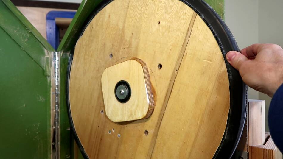
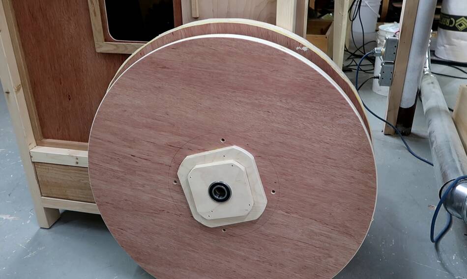
This is the upper wheel of my 20" bandsaw,
made of two pieces of 3/4" plywood glued together.
But all that plywood adds inertia, which makes starts and stops a bit
slower. It also makes the saw heavier.
So for my bigger 26" bandsaw build, the wheels would be 70% heavier still. So
I wanted to try making the wheels hollow to make them lighter.
I could also cut holes in the solid plywood to make it lighter, but that would make
the wheel act more like a fan, which will in turn whirl around dust more. Another approach
would be to make them of one layer with wider flanges, but on my
18 bandsaw I found that shape tends to guide
dust behind the inner tube tires.
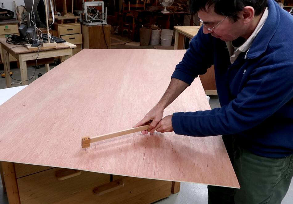
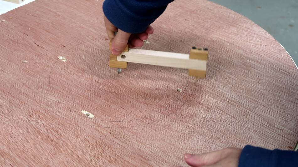
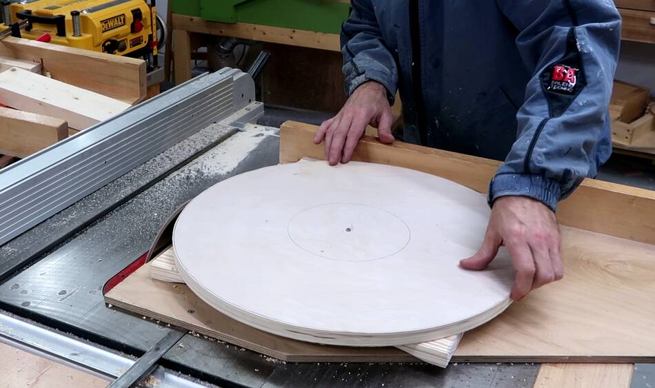
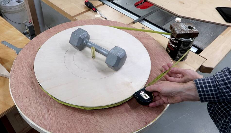
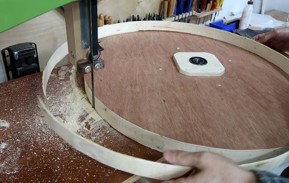
I started by drawing 26" circles on a full 4'x8' sheet
of plywood with my beam compass.
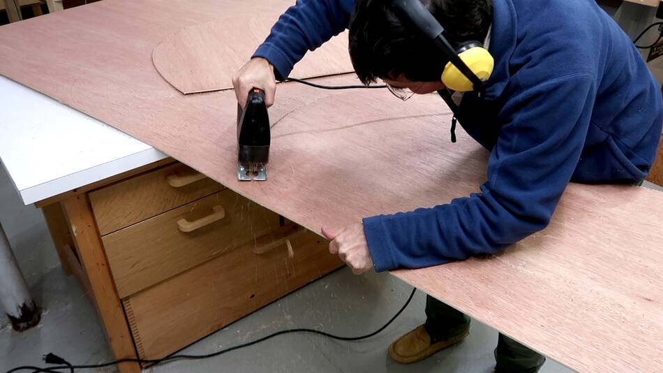
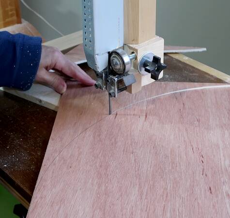
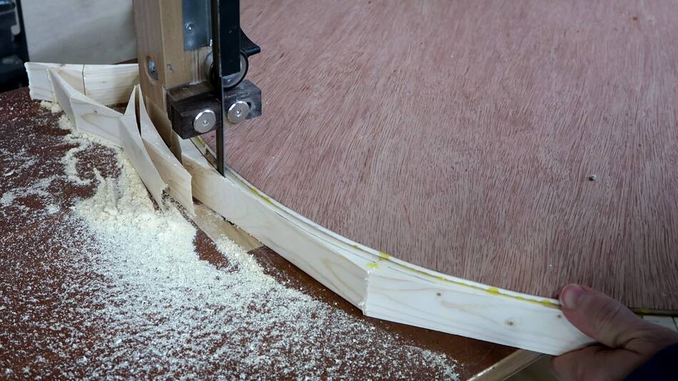
Then rough cutting the circles out with a jigsaw, and finishing
the cuts on a bandsaw. This could of course be done with a jigsaw as well,
but I already have some bandsaws, and a bandsaw is a better tool for that!
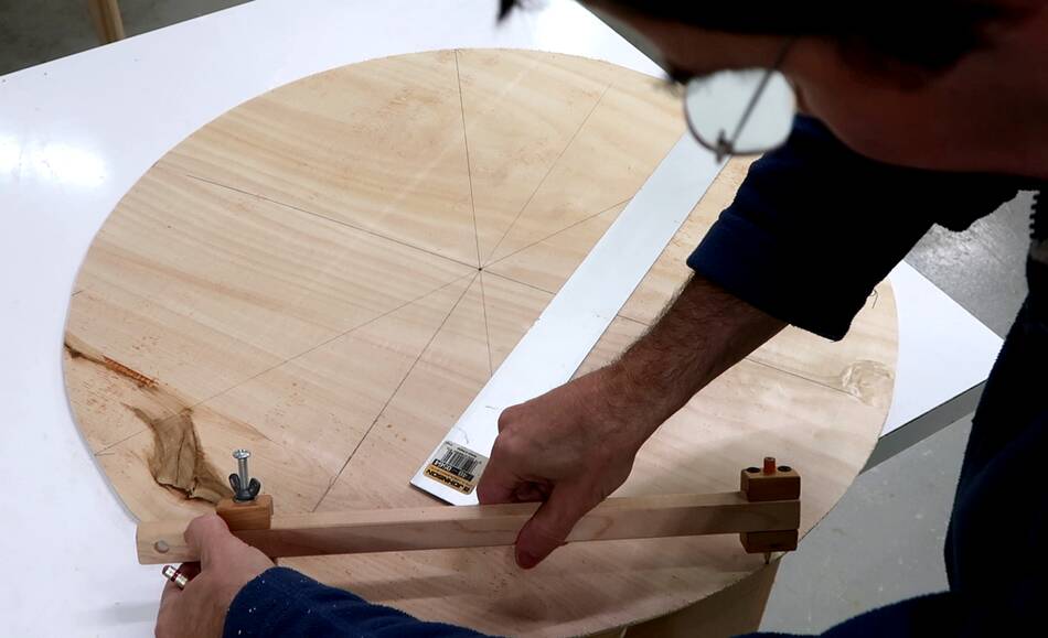
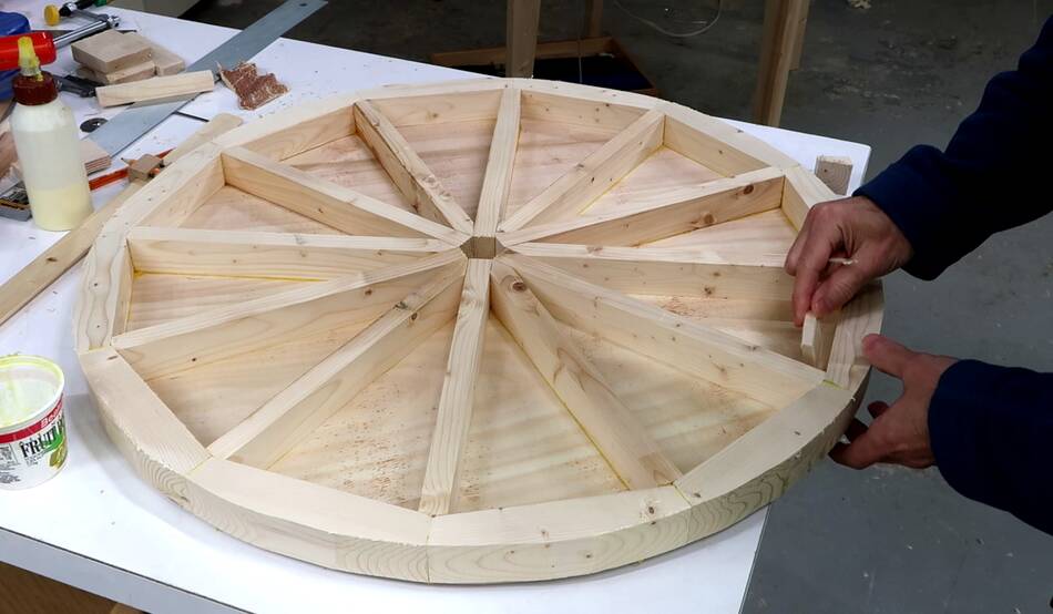
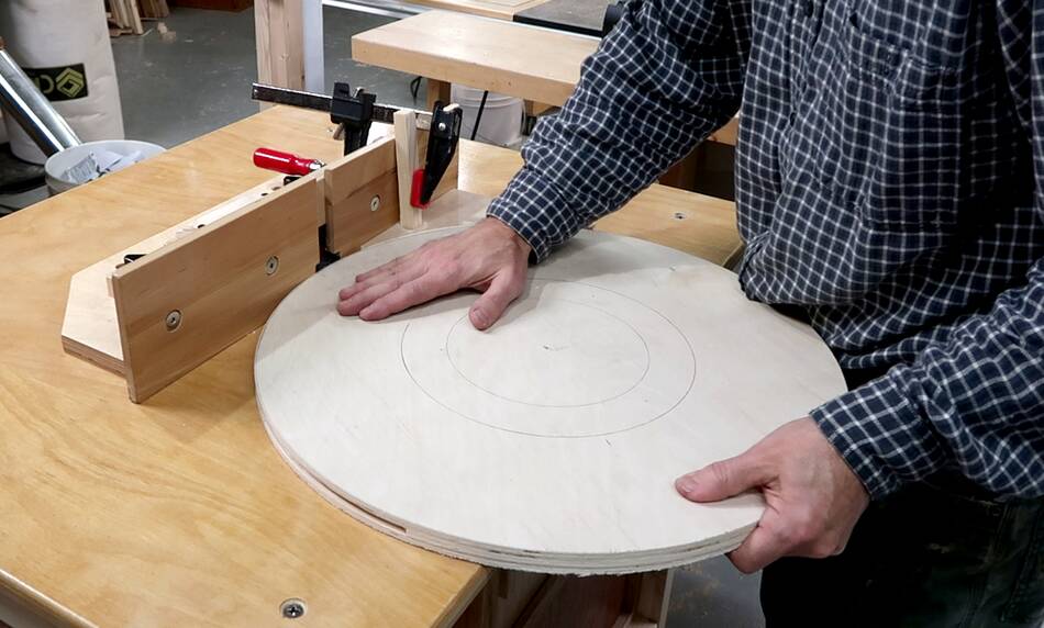
Having cut out the circles, I laid it out for twelve spokes. I started by drawing
two lines at 90 degrees, then got the 30 degree increments by using my
beam compass
to mark 60 degrees from the lines intersecting at 90 degrees.
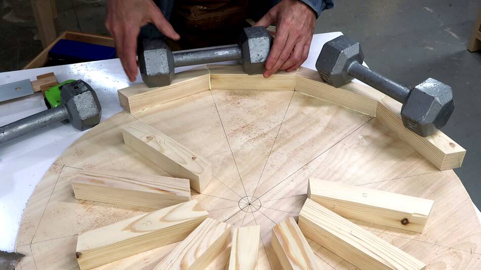
I started by gluing pieces around the rim for my first wheel, then the spokes.
But getting the spokes in with the rim already glued was tricky.
So for the second wheel I glued the spokes down first, then the rim pieces
against the ends of the spokes. All joints are just butt joints.
Every second spoke piece is pointy towards the middle to fit between the other
spokes.
Then cutting off the parts of the rim that went beyond the circle.
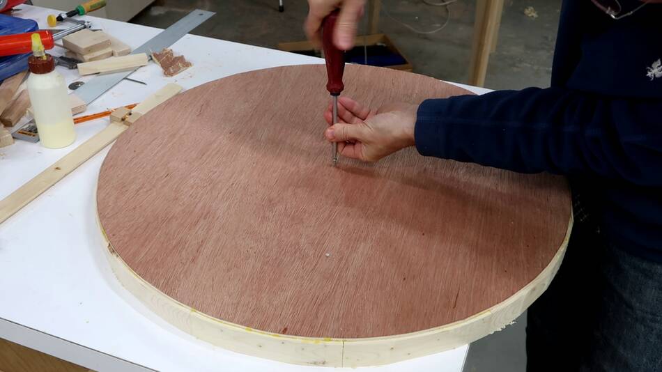
After that I put a small round headed screw into the center hole and flipped
the wheel with the screw facing down.
With the wheel balanced on the head of the screw, I checked the balance.
I added a small block of wood to balance it. This is just an approximate
balancing. I will have to re-balance the wheels once they are all done, but
by that point, I won't be able to add a weight to the inside.
I made sure that all the rim pieces came from the same piece of wood, so they
would have about the same density and not throw the wheel off balance.
The spoke pieces are also all cut from the same piece of wood.
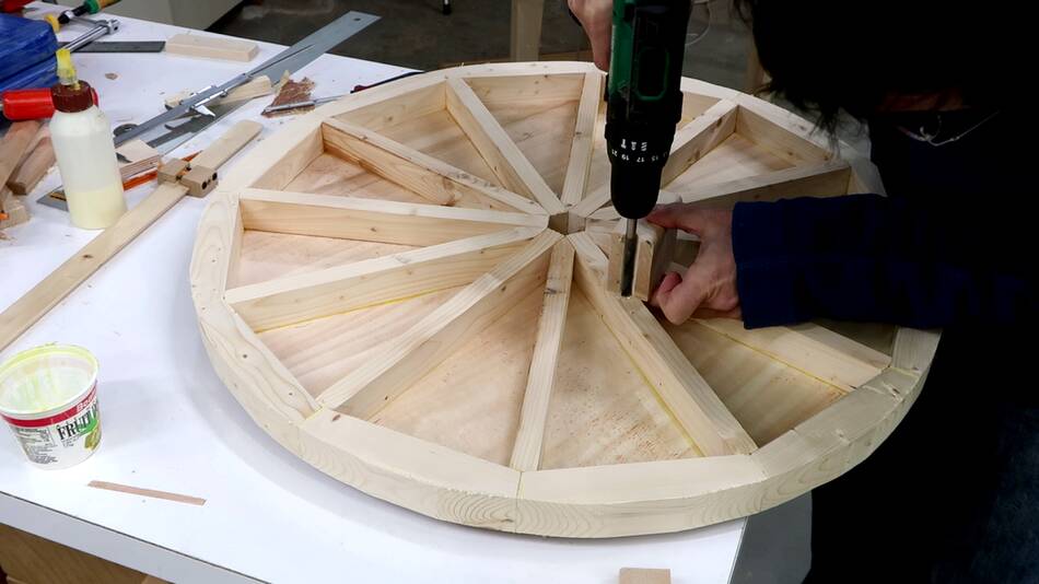
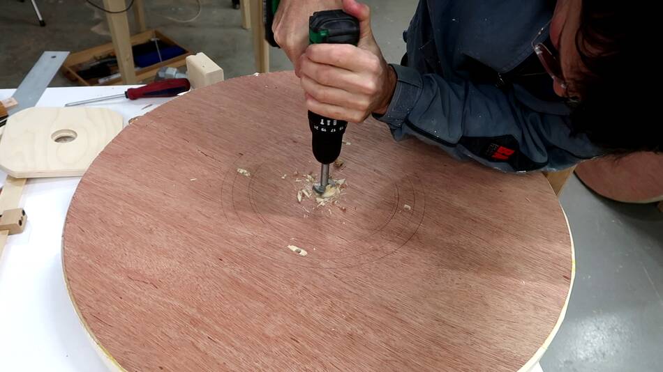
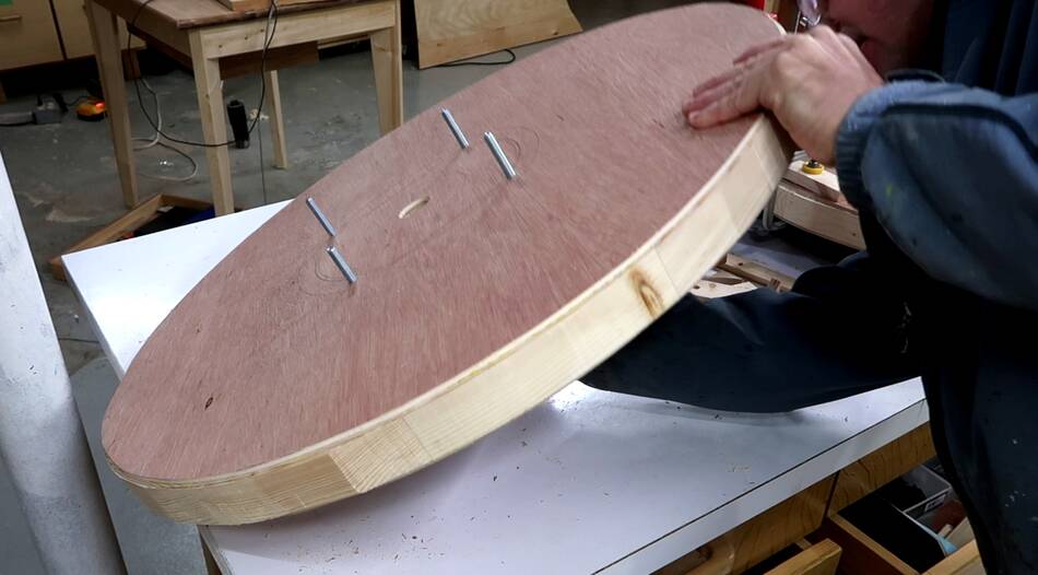
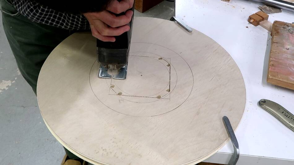
I drilled a hole, just a bit bigger than a 5/16" bolt (or 8 mm bolt)
through four of the spokes and through the plywood they are glued to.
Once I drill the shaft hole, I'll lose the precise center point of the wheel.
I used my beam compass to draw a few concentric circles from the center
to be able to re-align to the middle later.
After that, I drilled a 32 mm hole, which will leave reasonable clearance for
the 1" axle that will go through the wheel.
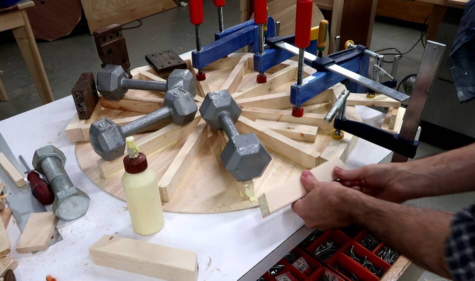
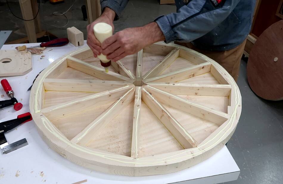
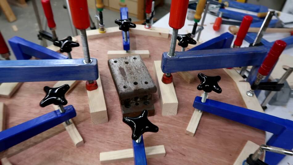
Then applying lots of glue to the spokes and the rim.
And gluing on the second layer.
I always give the plywood a light sanding where it's glued for critical glue-ups.
Not because the surface needs to be roughened up, but because atmospheric grime
deposits gradually build up on surfaces, which can reduce glue and paint adhesion.
and a light sanding gets rid of that.
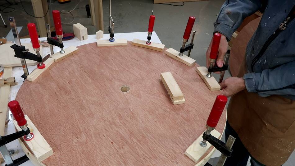
I used all six of my new long reach clamps
that I made for a recent table top glue-up to clamp closer to the middle.
Then some of my older long reach clamps to
glue closer to the middle, and some weights for the very center.
In retrospect, I could have drilled those four holes in the spokes through the
top layer and put bolts through those holes to help clamp it. Also a bolt and
a big washer through the center axle hole would also have helped clamp.
Sand bags would also have been useful for the clamping.
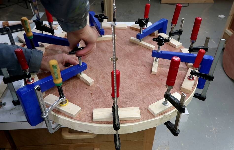
After the glue dried, I drilled the four holes through the spokes all the way
through and put some 4" long 5/16" (roughly 100mm M8) bolts through the holes.
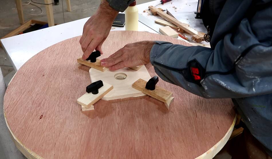
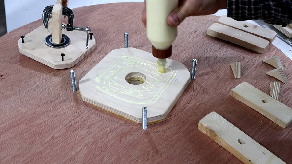
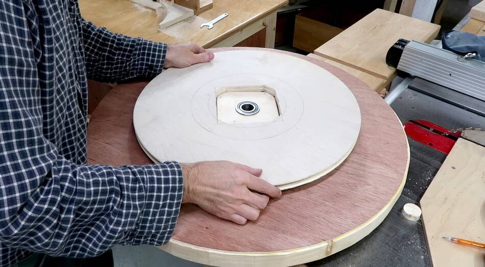
Using these four bolts, and some threaded knobs, I glued a flange to the
side of the wheel. This flange is a spacer so the bearing flanges will be
further apart, which should give the wheel more side-to-side stability.
After clamping it with the four knobs, I realized I could just barely fit
my dovetail clamps through the center axle hole for additional clamping.
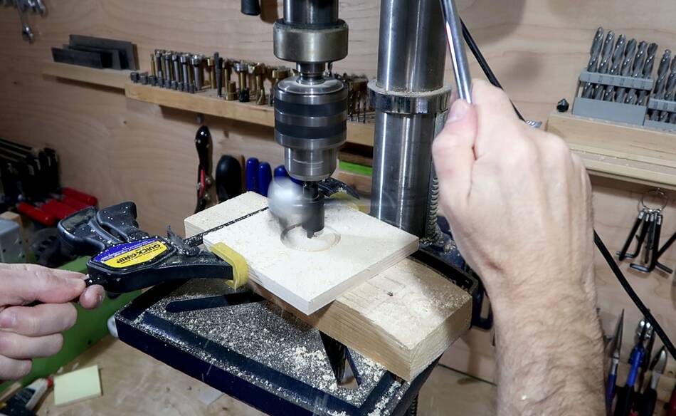
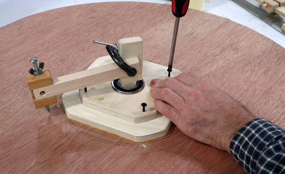
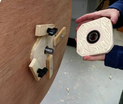
Next step was making the wheel flanges. I need precise holes that the
bearings fit into with a press fit. These flanges are critical, so I'm
making them from baltic birch.
Surprisingly, I managed to set the circle cutter set to the right diameter
on the first try. I set it with a caliper, taking the 52 mm for the bearing,
divide by two, gives 26, add half the diameter of the 6 mm center drill, so 26+3
= 29 mm, then subtract 0.2 mm to make it tight. So I set the callipers
to 28.8 mm, then with the callipers measuring from the center drill bit to the
edge of the cutter head, set it to that.
The circle cutter cuts slightly bigger the deeper it goes, just the way the
cutter is angled. To minimize this, I drilled to half depth, then flipped
the workpiece over. Using the hole from the cutter's center drill
as alignment, drilled in from the other side.
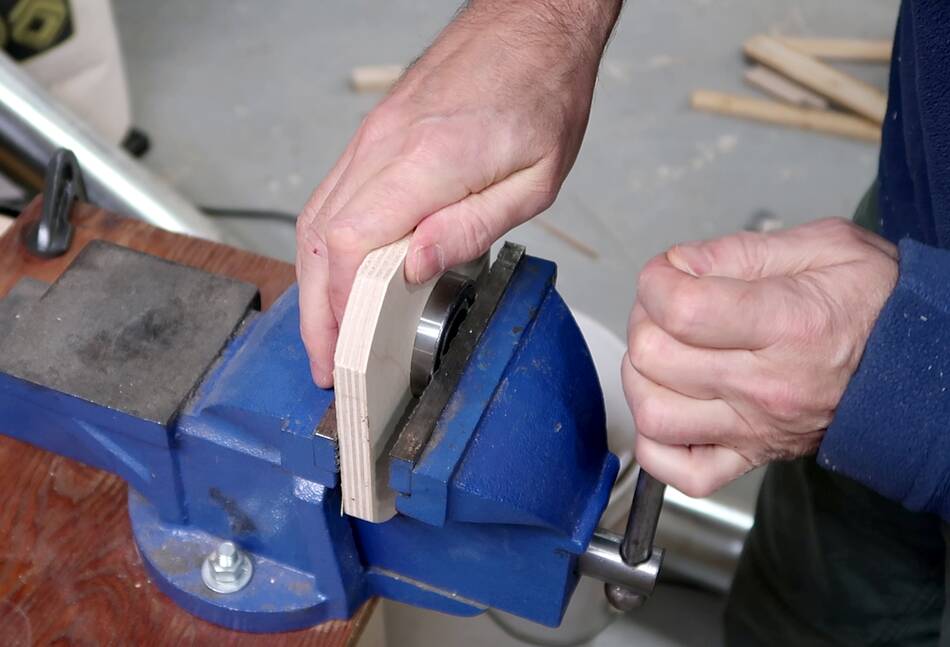
The bearings are a tight fit, and I had to use my vise to press them in. The
vise doesn't reach to the center point, is I kept pushing a little bit, unclamping,
rotating the flange 90 degrees, and squeezing some more, until the bearing
became flush with the wood and I couldn't press it any further.
The bearing needs to be in very tight because as the flange spins around the
axle, from the flange's point of view, the axle is pulling back and forth
as the wheel turns, and if that bearing can at all budge from repeated back and
forth, it will work its way out eventually. So it needs to be in there very
tight. If you can press it in by standing on it, it's too lose.
Spinning the flange and bearing on the shaft, I couldn't see any wobble. Very
satisfying!
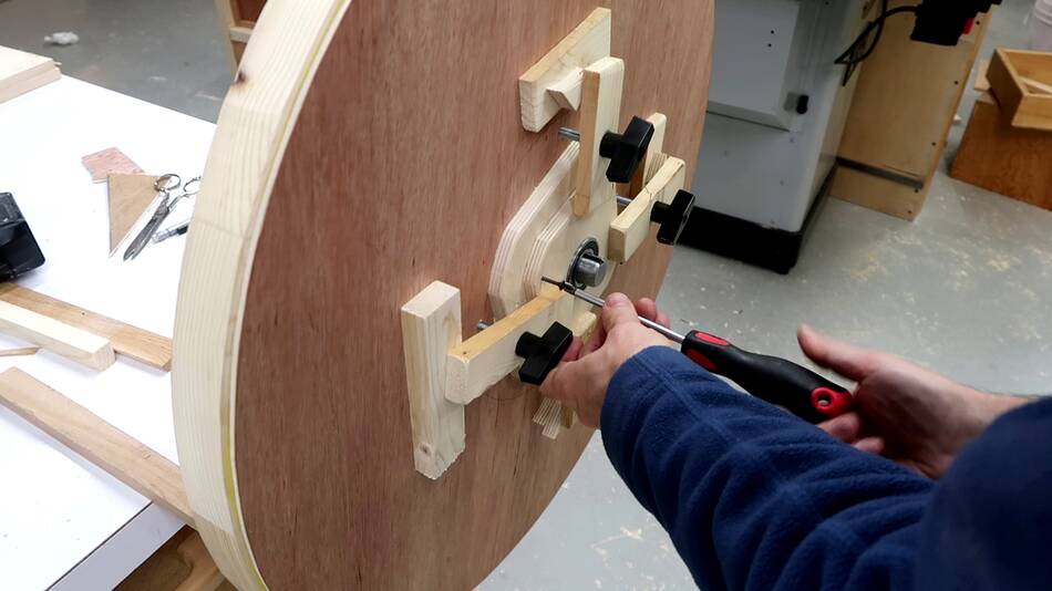
I drilled four screw holes near the corners of the bearing flange
and put screws in them, but not far enough for the screw points to come
out the other side. I then put the flange onto the other flange
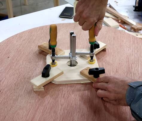
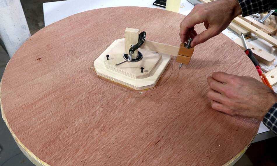
already on the wheel, and fastened a beam compass to a piece of wood stuck
into the bearing.
Swinging the point of the beam compass around, I adjusted the radius and
flange position until the compass point traced my old circle exactly. That way
I could be sure the flange was positioned on center.
I then held the flange down while turning the screws so they made divots into
the spacer flange below.
Then applying glue, then carefully placing the flange back so the screws went
into the divots they made before.
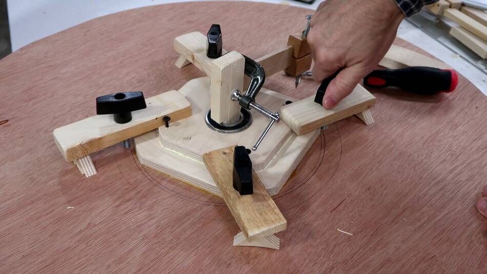
And then using the four bolts through the wheels to clamp the flange in place,
with the beam compass still fastened so I could check the position, though
with the screw knobs in the way I could only swing the beam compass
through less than a quarter turn. Maybe if
my reference circle had been much bigger, I could have reached over the knobs
and been able to check with the knobs in place.
Maintaining center is important. If I was off by a few millimeters,
I had enough margin that I could have trimmed the edge of the wheel to still make
it centered and the correct size, but the hollow space
in the middle would be off-center, which would throw the wheel substantially
out of balance.
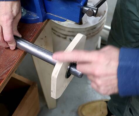
With just one bearing and flange mounted I tried spinning the wheel on
an axle. Hardly any side-to-side wobble at the wheels rim, much better
than I expected.
After that I glued on the spacer flange to the other side, then clamped the
bearing flange to the side, again using the bolts.
Spinning the wheel, I checked for side to side wobble. With the second flange
only positioned by friction, I kept tapping it with a mallet to move it to
eliminate the side-to-side wobble as well as I could. I got it down to
less than 1 mm.
Once I was satisfied with the alignment, I used the same screw-point divot trick
to lock the alignment of the flange. Then removing the flange I added
glue and put it back on, using the screw divots for alignment.
And why not do this whole procedure with glue on in the first place? Became
the glue is very slippery, so it drifts out of alignment as it's clamped.
And the glue's drying time is limited, so it's best to work out the alignment
before applying glue.
Having said that, after I clamped it on with glue, it was off by a little bit
and I had to tap it some more to fix that.
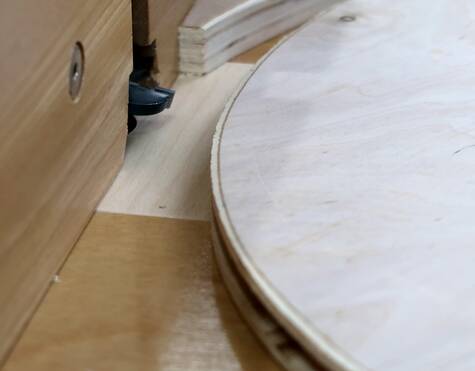
Making the drive pulley
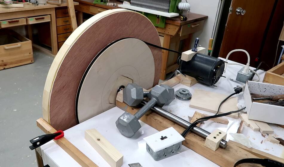
The next step is to turn (lathe) the wheels to true them up. For that I need
to spin them with a motor, so I made the drive pulley. I rough cut
it out of a sheet of 3/4" plywood with a jig saw, then spun it against a running
table saw blade to get it precisely round.
After that I cut a 1/4" slot around the circumference on my
new router table.
But the sides of the v-belt groove need to be slanted, so next I tilted
the tilting router lift to match the sides
of the belt and routed each side grooved.
Doing this on the router table felt much safer than
making it on the table saw, though if
you don't have a tilting router lift, the table saw is the way to go.
Then figuring out how long a belt I needed. I just wrapped a tape measure around
the pulley and a small paint can as a stand-in for the motor pulley.
I cut a square slot in the pulley wheel to fit around the bearing flanges.
Then placing it over the bearing flange in one of my wheels. I temporarily
held it on by putting some long screws through the holes I already had in the
wheels, pressing it against the big wheel.
It turns out I had it 1-2 mm off center, but for a temporary setup, I didn't
care that much.
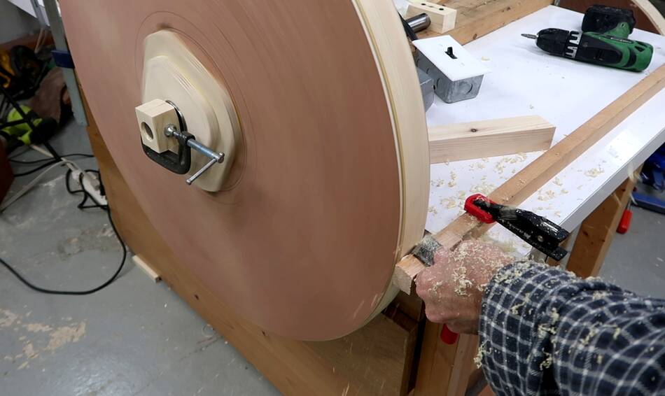
I ran the belt I bought around the pulley and a small motor
to spin up the wheel.
Then with a piece of wood clamped to my workbench as a tool rest, I started
turning down the wheel to true it and get it to the final size.
I had to take about 6 mm off the wheel after I trued it up. I had left
too much margin. I turned one side down to the size I needed, periodically
measuring the circumference until it was right, then turning down the rest
of it to size.
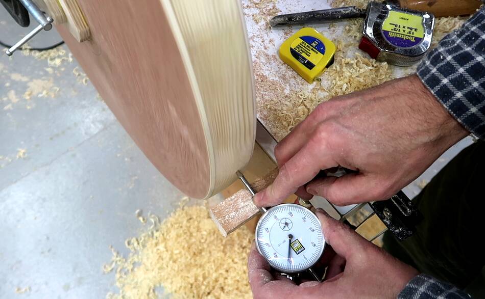
Checking it for round-ness with a dial indicator held against the wheel slowly
spinning. The dial indicator needle moved back and forth by nearly 0.010"
(0.25 mm) Too much. Each segment had a high and low spot because the
chisel grabbed better when it was cutting into the wood grain than out of it.
I gave the wheel a light pass with a sharp small turning chisel, and that
cut the remaining variation in half. I figured that was passable.
Comparing the turned wheel (in front) to the rough wheel behind, I ended up taking
off quite a bit! It was slow going lathing it with a chisel.
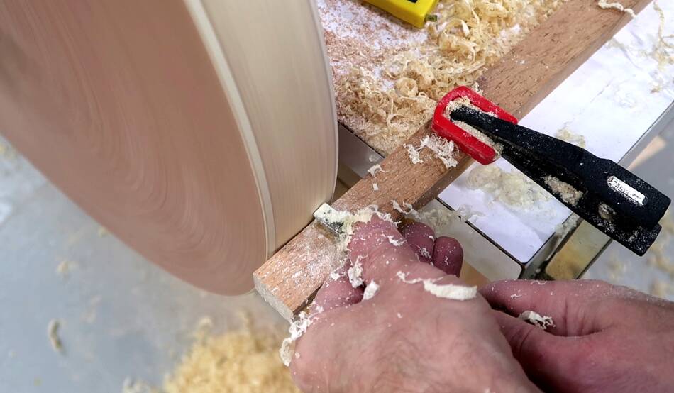
So for the next wheel, I cut off about 4 mm with the bandsaw before turning it.
This one went quicker than the first one.
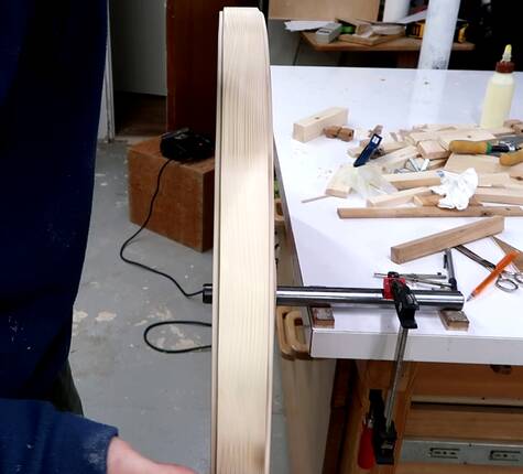
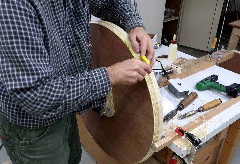
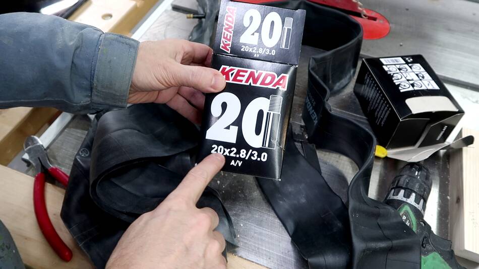
Bandsaw tires from inner tubes
I bought some larger sized inner tubes for the bandsaw this time. 1.75"
bicycle inner tubes would have been enough, but Princess Auto had these,
which were for fatter tires and maybe thicker.
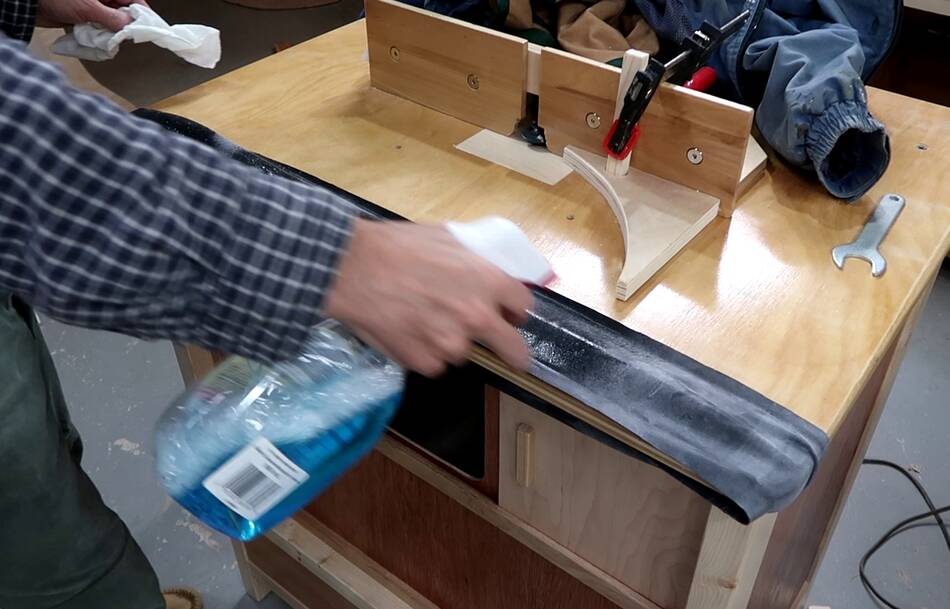
After cutting the inner tube open and cutting out a wide strip from the outside
of the tube, I cleaned off the chalky powder from the inside. This powder
is there to keep the inner tube from sticking to itself while folded up,
but for a bandsaw, I want the rubber to stick to the wheel, so the powder
has to come off.
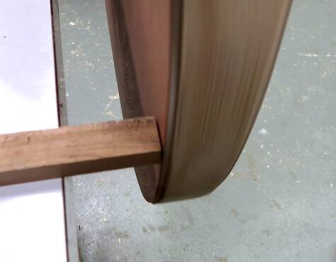
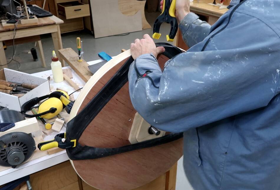
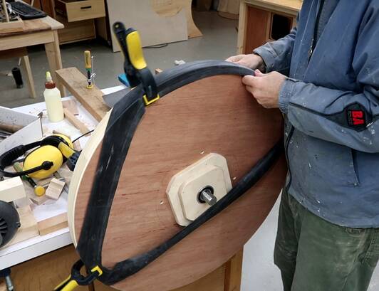
Then mounting the inner tube over the wheel. I start by clamping it to one side,
then stretching it across and clamping it on the other side. Then I stretch one
side to across to 90 degrees from where I clamped it on either side,
then pull the quarter sections over the wheel. After that, I stretch the
mid point over on the other side and repeat.
This way I don't end up with an unevenly stretched inner tube, which should make
the thickness of the inner tube more consistent as well.
I will later varnish these wheels, which will make the rim better for the
inner tube to stick to.
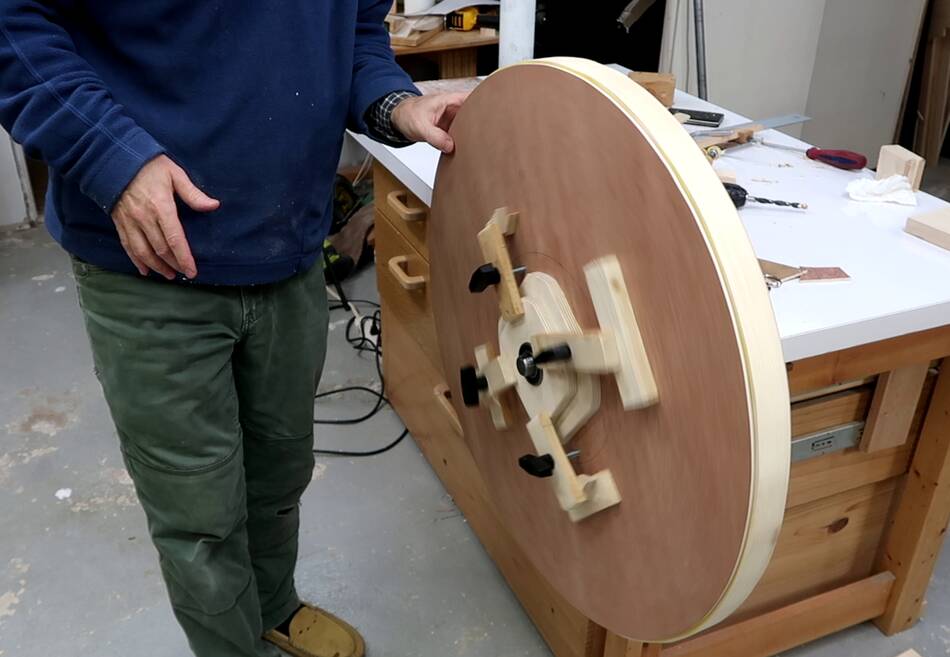
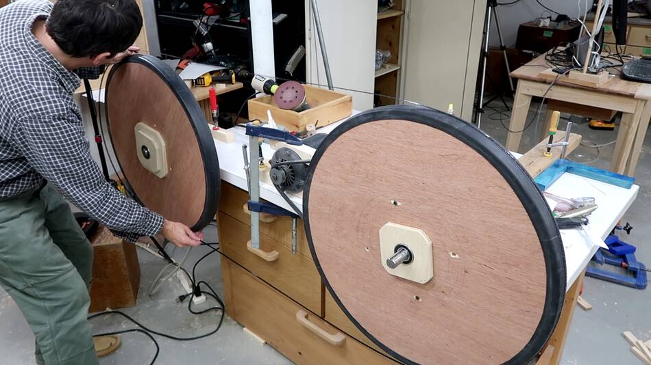
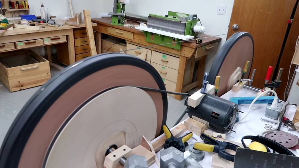
With the wheels done, I figured it would be fun to see if I could make a bandsaw
blade track on them. So I mounted the second wheel further down the
bench, put a blade on it, and spent some time getting the alignment
just right.
And with the motor turning one of the wheels, the 1/4" blade was able to track
without guides. So the wheels are good.
As usual, the video got a lot of comments, and a lot of those were repeated
in different forms many times. So I made a video answering some of these questions.
 This is the upper wheel of my 20" bandsaw,
made of two pieces of 3/4" plywood glued together.
But all that plywood adds inertia, which makes starts and stops a bit
slower. It also makes the saw heavier.
So for my bigger 26" bandsaw build, the wheels would be 70% heavier still. So
I wanted to try making the wheels hollow to make them lighter.
This is the upper wheel of my 20" bandsaw,
made of two pieces of 3/4" plywood glued together.
But all that plywood adds inertia, which makes starts and stops a bit
slower. It also makes the saw heavier.
So for my bigger 26" bandsaw build, the wheels would be 70% heavier still. So
I wanted to try making the wheels hollow to make them lighter.
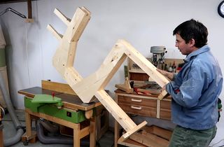 Making thre 26" bandsaw frame
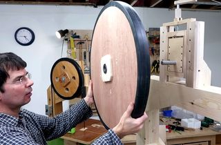 26" bandsaw wheel mounts
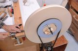 20" bandsaw wheels from solid plywood (much simpler)
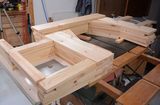 20" bandsaw frame
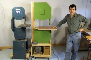 My 18" bandsaw (the
 My 20" bandsaw build