 I often get asked questions about motors, so I figured I'd do an article
and video about how they work.
I often get asked questions about motors, so I figured I'd do an article
and video about how they work.
I often get asked questions about motors, so I figured I'd do an article
and video about how they work.
There are two main types of motors used in most applications: DC (or universal) motors and induction motors. DC motors are much easier to understand, so I will start with those.
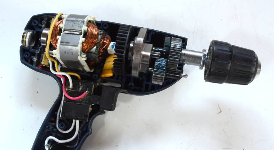
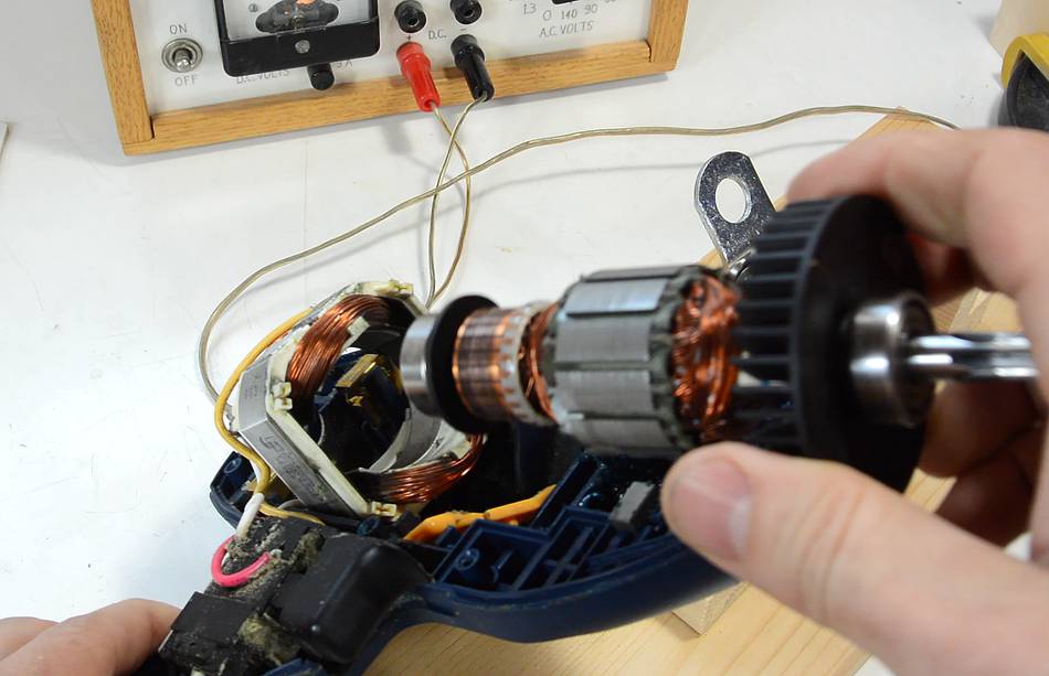
Universal motors are used in most hand held power tools, such as drills, routers, jigsaws and sanders.
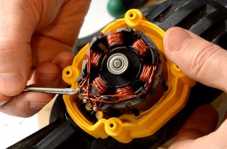
I opened up one of my drills to show the insides and take out the rotor to demonstrate it.
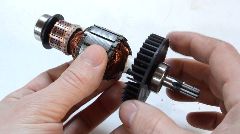
 The rotor of a conventional DC motor consists of a metal core with
copper windings on it, which are connected to contacts on one end.
These contacts are called the "commutators".
The rotor of a conventional DC motor consists of a metal core with
copper windings on it, which are connected to contacts on one end.
These contacts are called the "commutators".
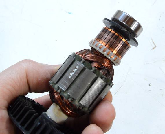
 These windings and contacts are arranged in such a way that if current
is applied to the contacts of the commutator on opposite ends, the rotor
forms an electromagnet, with north and south lined up with the contacts
where current is applied.
These windings and contacts are arranged in such a way that if current
is applied to the contacts of the commutator on opposite ends, the rotor
forms an electromagnet, with north and south lined up with the contacts
where current is applied.
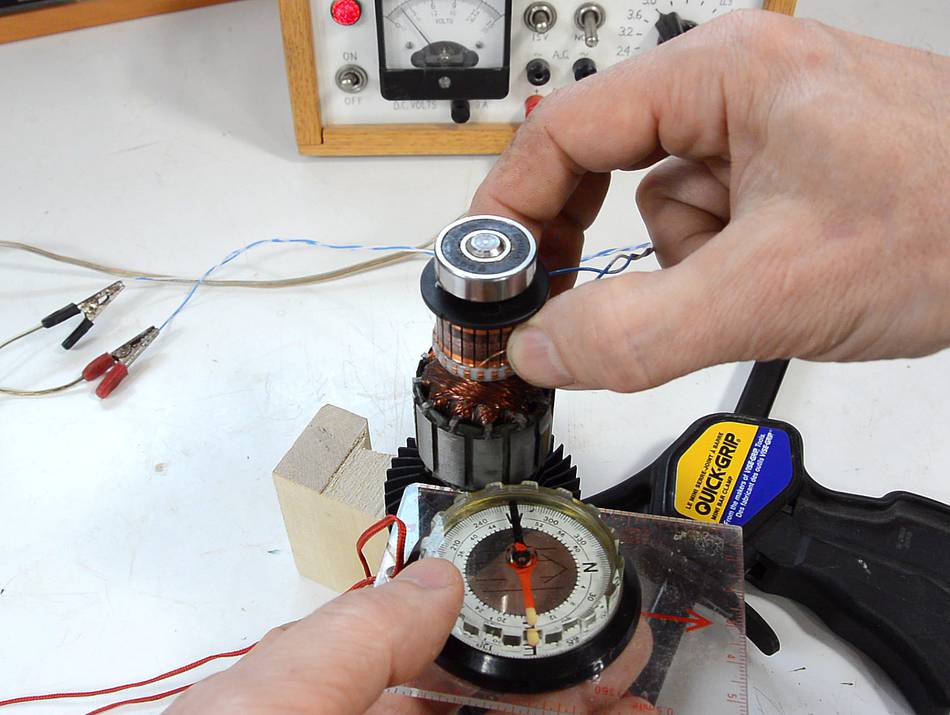
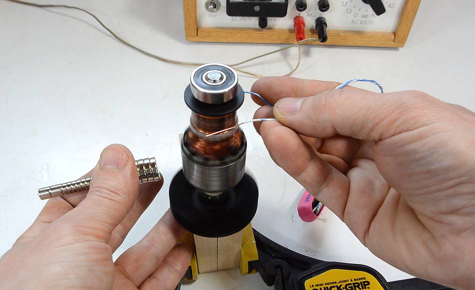
Here I'm applying a current, using thin telephone wires pushed against the commutators and checking the magnetic field with a compass. If I change where I'm applying the current (to different commutators) them magnetic field also rotates to line up with the commutators I'm applying current to.
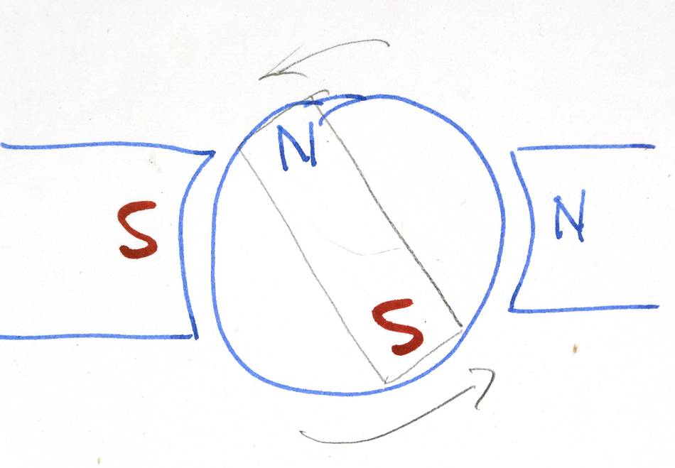 The way a DC motor works is that the rotor acts as an electromagnet,
which is typically about 90 degrees out of alignment with the poles
surrounding it (the stator). North and south poles of magnets
attract each other. So magnetic attraction wants to turn the
rotor to align it with the stator.
The way a DC motor works is that the rotor acts as an electromagnet,
which is typically about 90 degrees out of alignment with the poles
surrounding it (the stator). North and south poles of magnets
attract each other. So magnetic attraction wants to turn the
rotor to align it with the stator.
If the rotor and stator of our motor were permanent magnets it would only turn 1/4 turn and then stop.
 But the rotor is an electromagnet and, as it rotates, current is
applied to different contacts on the commutator. Here with telephone
wires, but in a motor with pieces of carbon (which don't wear out as
quickly). I'm only applying current from a 1.5 volt battery here, and
holding a magnet next to the rotor. This is actually enough to make it
turn, slowly.
But the rotor is an electromagnet and, as it rotates, current is
applied to different contacts on the commutator. Here with telephone
wires, but in a motor with pieces of carbon (which don't wear out as
quickly). I'm only applying current from a 1.5 volt battery here, and
holding a magnet next to the rotor. This is actually enough to make it
turn, slowly.
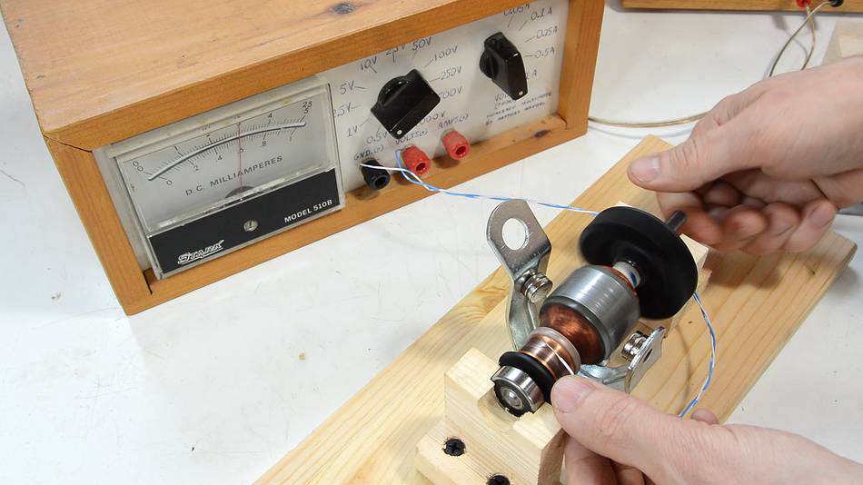
 The above demonstration does not make for a very good motor. Holding
magnets next to the rotor is not the best way to subject it to a
magnetic field. The "flux" of the magnetic field needs to form a loop,
but the magnetic flux doesn't pass very well through air. Iron is about
a thousand times more magnetically permeable than air (that's why the
motor uses iron in the rotor). I bent a 2 mm thick piece of iron into a
C-shape, and stuck some rare earth magnets to the inside of it. I also
made some blocks to hold the bearings. Now, applying 1.5 volts, it
turns much better, though still not very fast.
The above demonstration does not make for a very good motor. Holding
magnets next to the rotor is not the best way to subject it to a
magnetic field. The "flux" of the magnetic field needs to form a loop,
but the magnetic flux doesn't pass very well through air. Iron is about
a thousand times more magnetically permeable than air (that's why the
motor uses iron in the rotor). I bent a 2 mm thick piece of iron into a
C-shape, and stuck some rare earth magnets to the inside of it. I also
made some blocks to hold the bearings. Now, applying 1.5 volts, it
turns much better, though still not very fast.
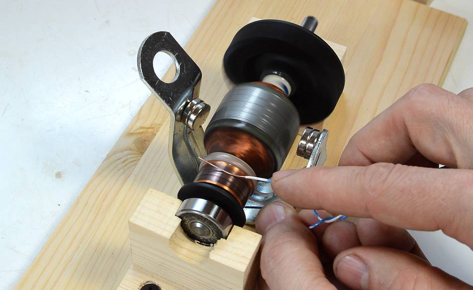
 Part of the problem is that the motor also acts as a generator. Here,
I'm spinning up the rotor manually, and I get voltage readings as
high as 0.6 volts, just from this arrangement. As the motor
spins, the changing magnetic fields induce a reverse-voltage in the
coils, and that limits the speed the motor will spin at for a given
voltage.
Part of the problem is that the motor also acts as a generator. Here,
I'm spinning up the rotor manually, and I get voltage readings as
high as 0.6 volts, just from this arrangement. As the motor
spins, the changing magnetic fields induce a reverse-voltage in the
coils, and that limits the speed the motor will spin at for a given
voltage.
Next I applied 30 volts to the rotor, and that got it spinning scary fast, considering it's just sitting loosely in this arrangement. But universal motors, in real operation, usually run at about 100 to 200 turns per second.
 My improved way of holding the magnets is still not optimal compared to
an actual motor. In a real motor the stator is made of
a lot of iron, which gives lots of room for the magnetic flux to form a
loop, so the rotor is subject to much more magnetism.
My improved way of holding the magnets is still not optimal compared to
an actual motor. In a real motor the stator is made of
a lot of iron, which gives lots of room for the magnetic flux to form a
loop, so the rotor is subject to much more magnetism.
The stator also closely follows the curvature of the rotor, so that the magnetic flux needs to travel through an air gap less than 1 mm thick.
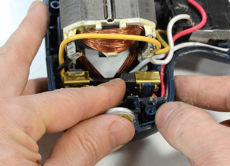 In a real motor, the current is applied to the commutator with carbon
"brushes". I imagine the "brushes" in the first electric motors really
were like brushes, but pieces of carbon are always used today. The
carbon slides with relatively little wear on the commutator. But it
does wear, so the brushes always have springs behind them to keep
pushing them closer to the commutator as they wear away. Eventually,
the brushes get too worn away to make effective contact.
So this type of motor is fine to use for hand held tools where,
if it stops working, it won't cause major problems. But for applications
where a motor has to run unattended for long times (such as in a
refrigerator, heating furnace, sump pump, or bathroom fan) induction
motors are used instead.
In a real motor, the current is applied to the commutator with carbon
"brushes". I imagine the "brushes" in the first electric motors really
were like brushes, but pieces of carbon are always used today. The
carbon slides with relatively little wear on the commutator. But it
does wear, so the brushes always have springs behind them to keep
pushing them closer to the commutator as they wear away. Eventually,
the brushes get too worn away to make effective contact.
So this type of motor is fine to use for hand held tools where,
if it stops working, it won't cause major problems. But for applications
where a motor has to run unattended for long times (such as in a
refrigerator, heating furnace, sump pump, or bathroom fan) induction
motors are used instead.
There is also a detailed Wikipedia article on commutators, which goes into much more detail on this type of motor.
Stepper motors
Stepper motors are used in many computer peripherals, especially
scanners and older printers. They are also used for controlling home
built CNC routers. They often make a whining sound when moving longer
distances. Their advantage is that a computer can precisely control
their rotation without the need for additional feedback sensors.
However, they are not very fast, efficient or powerful. Their main
advantage is computer controlabililty at low cost.
Induction motors
Induction motors are usually used in stationary machines that have to
run for long periods. They are actually much simpler in construction
than DC motors, but they are harder to explain. I have written
a separate article about indcution motors.
 Gyro effect explained
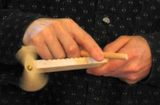 The hui game Also
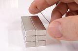 Magnetic repulsion lifts graphite (video only)
More relating to motors:
 Brushless DC motor, and a dumb way to drive it (video only)
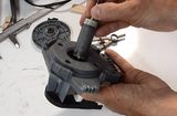 dishwasher wet rotor synchronous motor
 Fun with the venturi
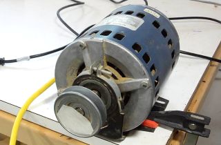 How AC (induction)
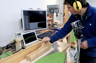 Induction motor vs. universal motor on my jointer, comparison
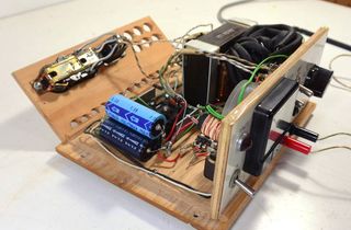 Homemade benchtop
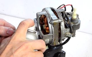 Fixing seized
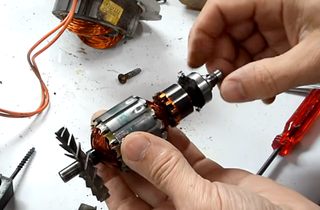 Oiling a noisy shopvac motor
 How crowned pulleys
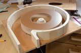 Blower design
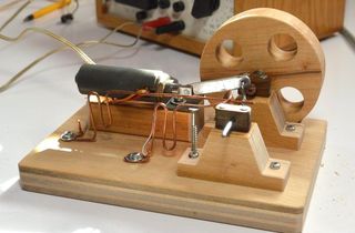 Solenoid engine
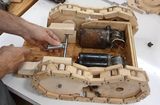 Restoring the wiper motor powered forklift toy