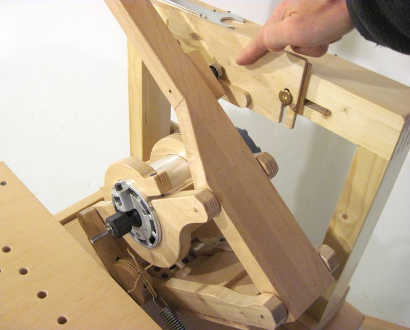
 The "Pantorouter" is a template guided router for cutting shapes in wood.
The template is mounted on the frame above the router. A ball
bearing on the pantograph mechanism is used to follow the template.
The "Pantorouter" is a template guided router for cutting shapes in wood.
The template is mounted on the frame above the router. A ball
bearing on the pantograph mechanism is used to follow the template.
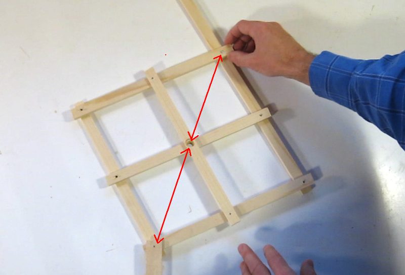 For those not familiar with pantographs, the lattice pictured at left should
help explain. The six pieces of wood are connected with pins at the corners.
The four areas inside this lattice each form a rhombus of equal dimensions.
For those not familiar with pantographs, the lattice pictured at left should
help explain. The six pieces of wood are connected with pins at the corners.
The four areas inside this lattice each form a rhombus of equal dimensions.
With the rhombuses all the same size and shape, you can see that the distance between the point that I'm holding and the fixed point on the opposite corner will always be divided exactly in half.
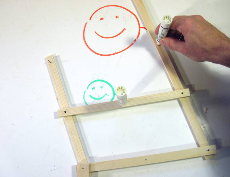 The linkage shown previously doesn't actually need all those pieces to work. In a pantograph,
the redundant links are not present. Scalings other than 2:1 are possible with most
pantographs, but for the sake of simplicity, my pantorouter has the reduction fixed at 2:1.
The linkage shown previously doesn't actually need all those pieces to work. In a pantograph,
the redundant links are not present. Scalings other than 2:1 are possible with most
pantographs, but for the sake of simplicity, my pantorouter has the reduction fixed at 2:1.
With a pair of markers in the pantograph, a shape drawn with the red marker will be drawn at half that size by the green marker.
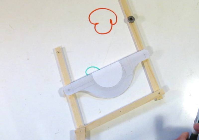 On my pantorouter, I use a ball bearing to follow the template in place of the
red marker, and mount my router where the green marker was.
The router mount is an odd shape so that the router's axis goes exactly
where the marker was.
On my pantorouter, I use a ball bearing to follow the template in place of the
red marker, and mount my router where the green marker was.
The router mount is an odd shape so that the router's axis goes exactly
where the marker was.
The pantorouter is basically the same linkage as this but built much sturdier to support the weight and cutting forces of the router.
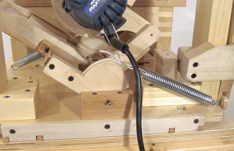 When I prototyped my machine, I found that pulling up on
the handle against the weight of the router was tiring over time. So I added
some springs, string, and cams to counteract the weight of the router.
When I prototyped my machine, I found that pulling up on
the handle against the weight of the router was tiring over time. So I added
some springs, string, and cams to counteract the weight of the router.
The cams are shaped such that the spring's tension profile is matched to the way that gravity exerts a larger moment on the router the further it is away from the pivot. There's one spring for each arm of the pantograph, one mounted behind, the other in front of the pantograph.
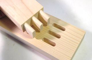
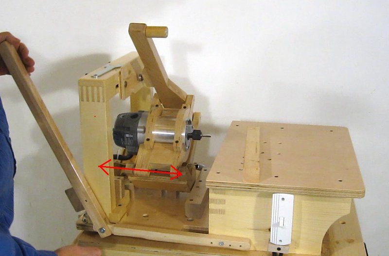 For routing internal cavities such as mortises, it's also necessary to plunge
with the pantorouter. I added a plunge mechanism by making the whole back half of the
machine move back and forth on a sled. A lever attached to the side
moves the plunge sled.
For routing internal cavities such as mortises, it's also necessary to plunge
with the pantorouter. I added a plunge mechanism by making the whole back half of the
machine move back and forth on a sled. A lever attached to the side
moves the plunge sled.
The sled moves back and forth on linear glides that I made from drawer slides
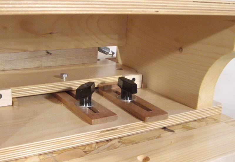 I also added some depth stops to the plunge mechanism. These allow me to limit how deep
the router will plunge. The second stop on the left limits how far back the router
can travel. This is useful for locking the plunge position in place. It can also be used
for setup. I'll often use the tip of my router as a stop for where to position the
stock. I'll move the router all the way back, and slide the piece against the router until
it hits the bit. Then I use the plunge mechanism to cut the desired depth.
I also added some depth stops to the plunge mechanism. These allow me to limit how deep
the router will plunge. The second stop on the left limits how far back the router
can travel. This is useful for locking the plunge position in place. It can also be used
for setup. I'll often use the tip of my router as a stop for where to position the
stock. I'll move the router all the way back, and slide the piece against the router until
it hits the bit. Then I use the plunge mechanism to cut the desired depth.
I should add that this does not involve starting the router with the bit touching the stock. I can always move the router out of the way sideways.
 Using the pantorouter
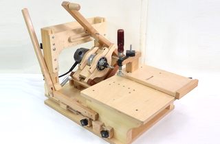 More about
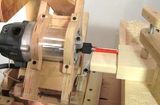 Big mortise and tenons
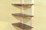 Mortised shelves