Mac Sheldon has started
distributing
the pantorouters made by Kuldeep.
He wanted a display showing a scaled-up animated pantograph to demonstrate how following
the template can be used to cut a tenon. He asked me if I could build such a thing
so he could show it at the wood show in Baltimore, Jan 2016.
I don't normally take commissions, and there really wasn't a whole lot of time to make this.
But it was an interesting challenge and would help to sell
pantorouter machines, so I started tinkering around with it.
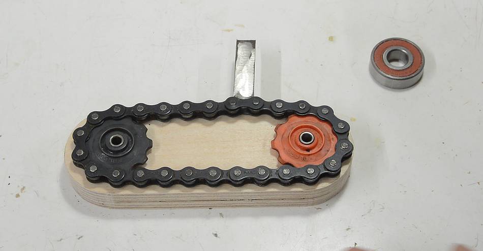
I took one of the feed roller drive chains from my
old thickness planer that I had smashed to
build a build a jointer. This chain seemed a reasonable
length. It was also the same pitch as a bicycle chain. Some plastic sprockets from the
gear shift derailleur were about the right size for what I needed. I could have designed custom
sprockets with my gear generator, but cutting sprockets for
bicycle chains out of wood is iffy at best.
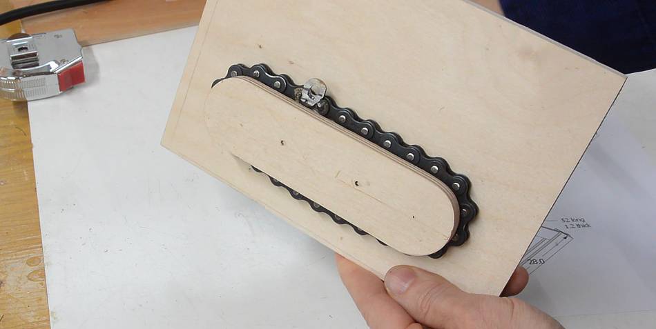
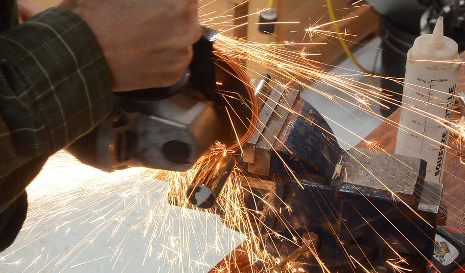
I welded a piece of metal to one of the links to pull the follower along.
The idea was that the sprocket mechanism would be hidden behind what represents the
pantorouter template, dragging a follower bearing around the template and so animating
the whole pantograph.
I sent pictures of what I had so far to Mac, and Mac mentioned he had been thinking of
using sprockets of 5-8" in diameter. In other words, what he had in mind was
something much bigger!
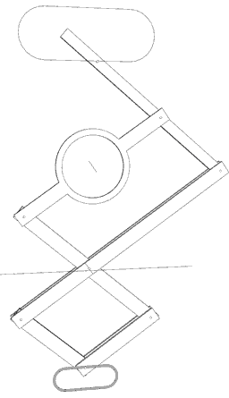
So I thought about what to do about this. Then I had the idea of making the pantograph
extend to "below the table", and have the chain mechanism there. That way the chain
could be at the same scale as the "tenon" being cut, and the pantograph would scale up
to a template that's twice as big.
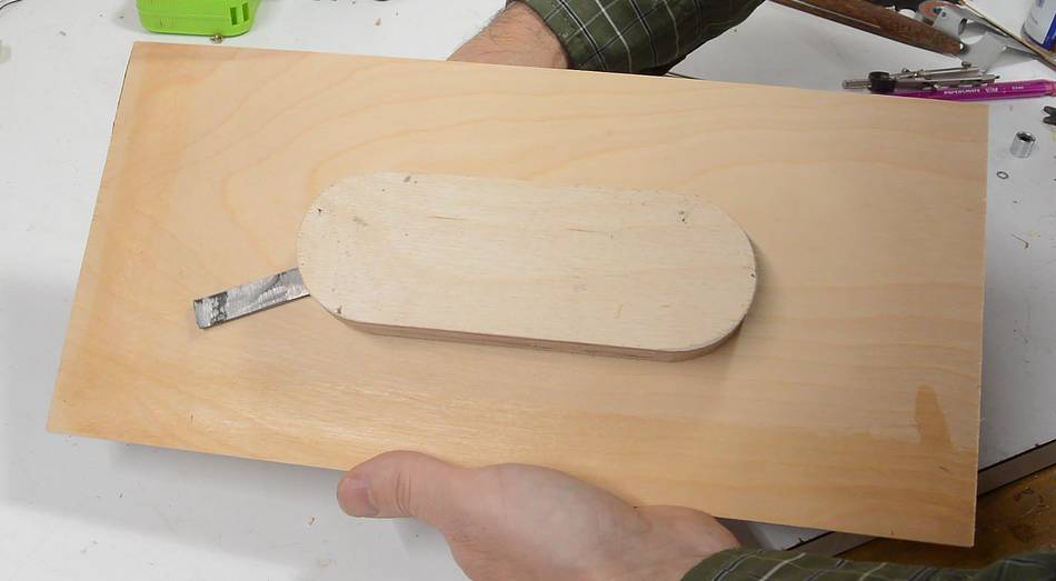
With the chain mechanism below the table, I could optimize for robustness instead
of making it hidden. So I drilled a hole in the strip of metal and shortened it so
it will hold the shaft near the chain.
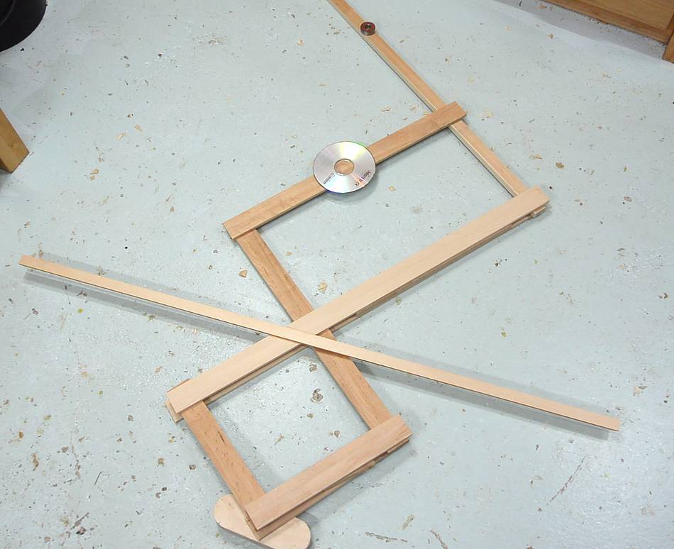
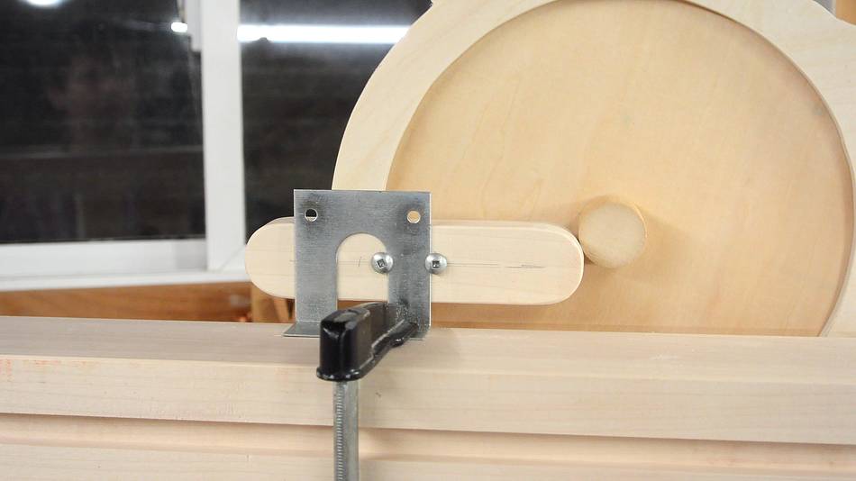
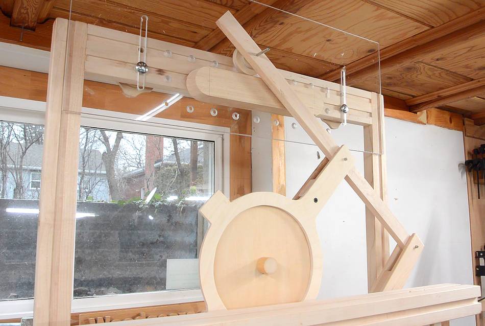
I cut out the pieces of wood for this and laid it out on the floor to make sure it's about
right. The CD-ROM represents the router, with a ball bearing above
that where the follower bearing is.
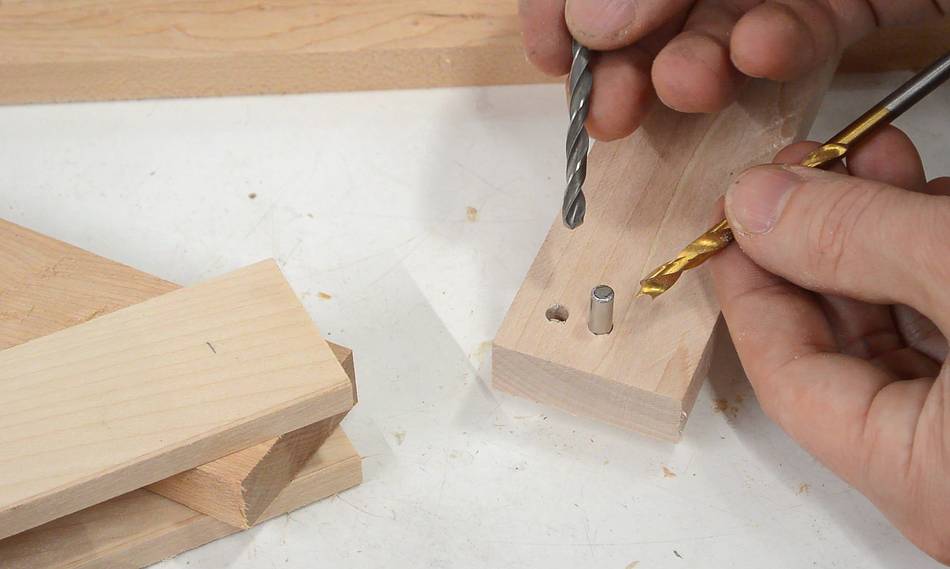
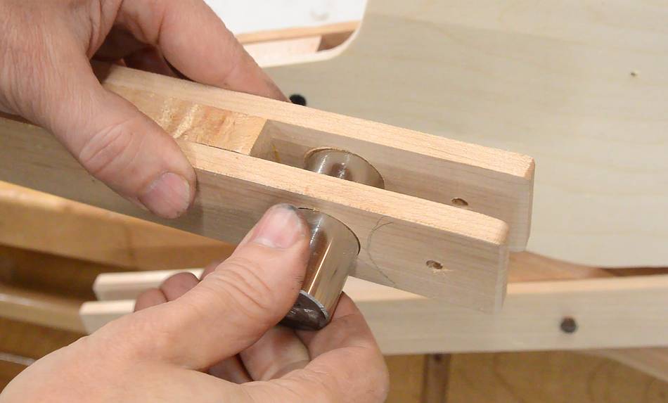
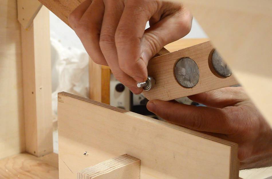
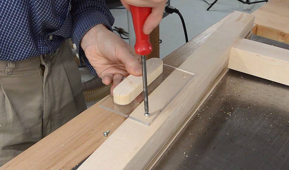
The mechanism pivots on 3/16" diameter shafts. I needed the shaft to turn freely in the
links, but not fall out. So for the "inside" layer, I drilled a hole that tightly
fit the shaft, and for the outside layer, I drilled it to fit loosely. The tight holes
are drilled with a 3/16" metal bit, the loose holes with a 3/16" brad point bit.
It's not unusual for metal drills to drill slightly undersized in wood, and brad point
bits to drill slightly oversized.
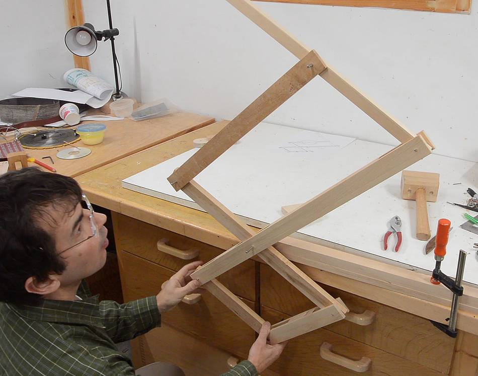
Pantograph assembled, and testing on my workbench.
It had a bit of friction between the links. Then I realized, with paint there would
be even more friction. So I made the pieces a bit thinner to cut down on
friction and leave some room for paint.
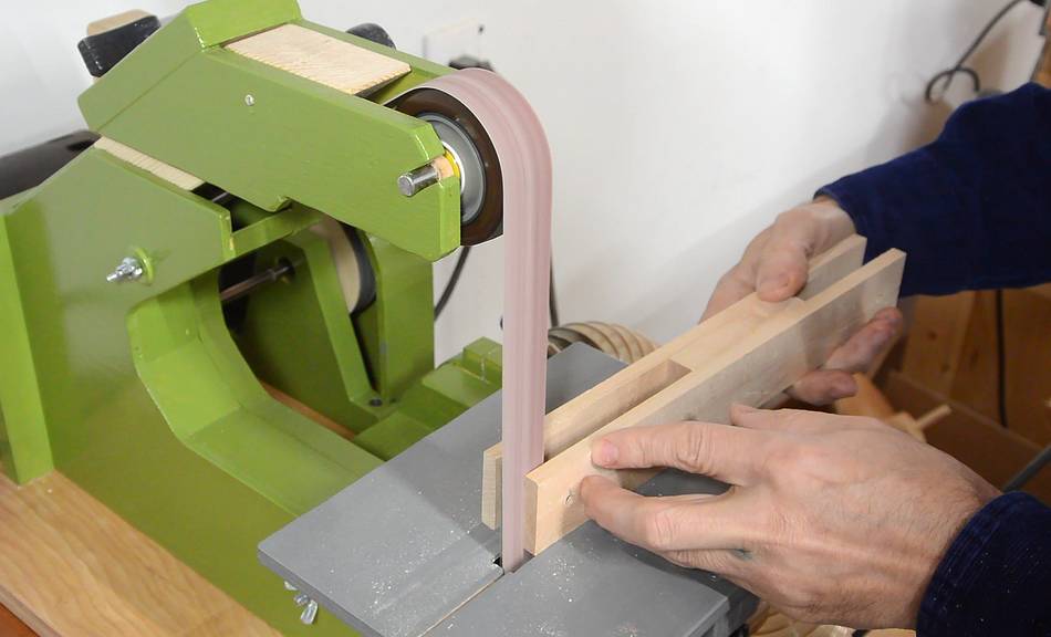
I rounded all the inside corners of the "outside" links on my
strip sander. That way, when it gets painted eventually, the paint won't get too scuffed
up where the links are.
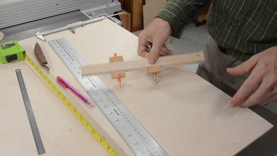
Next, drawing the "router mount" link on some plywood, using my
beam compass.
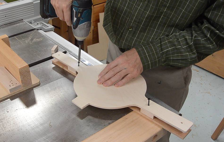
Assembling the router mount. The back is just a straight piece of wood.
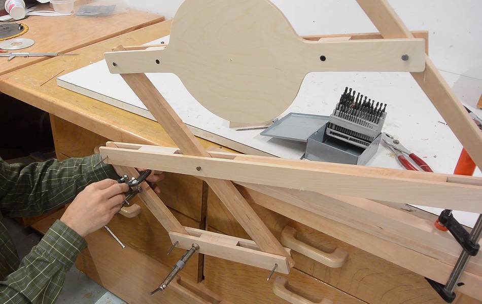
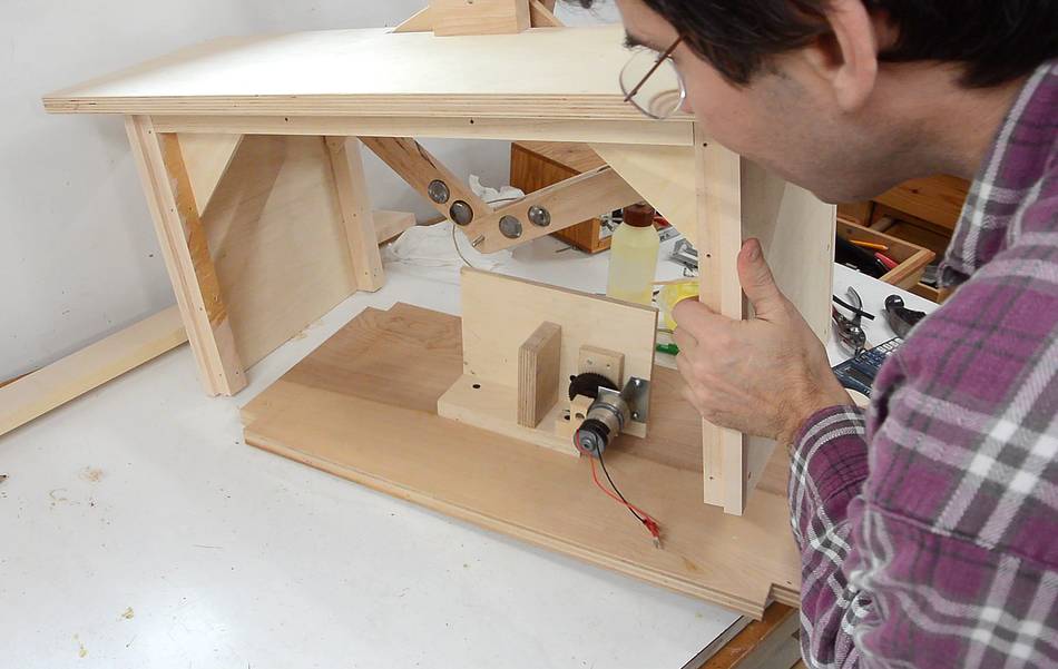
I used some C-clamps to weigh down the part of the pantograph below the table
to balance the part above the table. It took quite a bit of weight to counter balance.
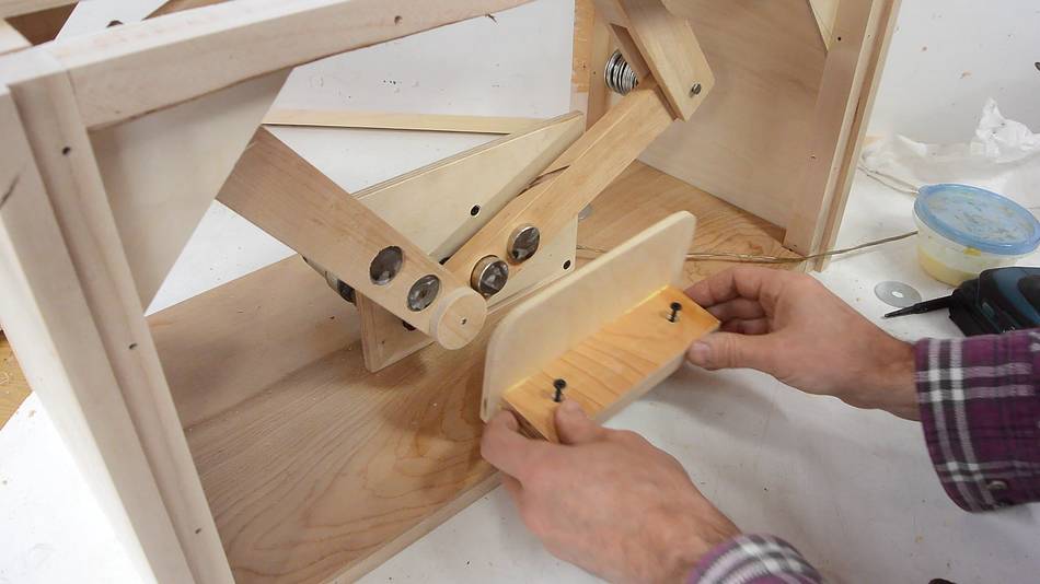
I cut up some 1 1/4" steel shaft to use as counterweights for my mechanism.
The pieces of steel shaft fit in holes in the links below the table.
Again, experimenting with balancing. By holding one set of links vertical, I was able
to balance the other set of links, then reoriented so the other set of links was vertical,
and balanced again. I used some large fender washers, hooked to extra long pins on the
pivots to do the fine balance.
I hollowed out the back of some of the links to cut down on how much counterweight I needed.
With part of the pantograph extending down, I needed a raised base for it.
I made a box out of thin plywood, using pieces of hardwood in the corners.
This was actually the second base. I initially miscalculated the height
so the first base wasn't tall enough. I turned that one into a
storage box.
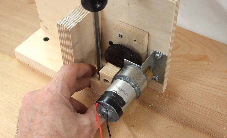
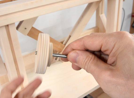
I had an old gear head motor with a gear on the output shaft, and I happened to have
another gear in my gears drawer that fit both the motor and the 8 mm shaft
that I used for the sprockets.
I found the shaft wiggled around a bit too much in my initial assembly, so here I'm
adding a bearing block to hold the other end of the shaft. The bearing block has
a steel bushing on the inside.
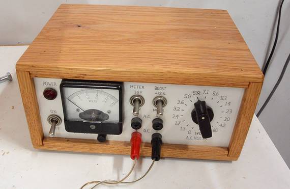
I used my benchtop power supply
to provide power, though I later swapped that for a small 7.5 volt wall power adapter.
Fitting the base into the box.
My box was initially to be held rigid by its sides, but I needed to be
able to access the front and back while working on it, so I added some cross
members and gussets on the inside to hold it rigid even without the front and back.
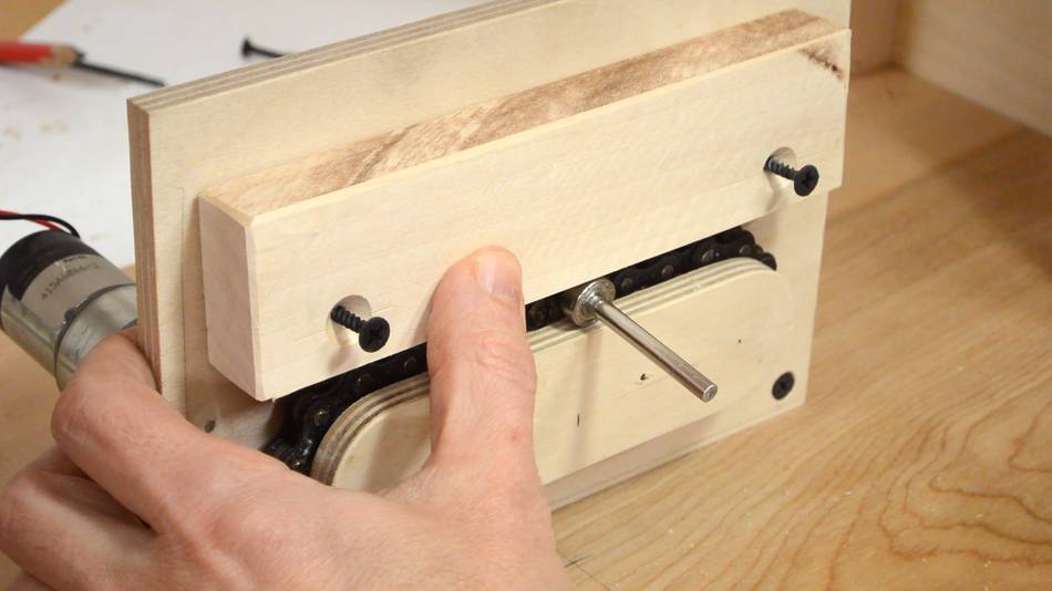
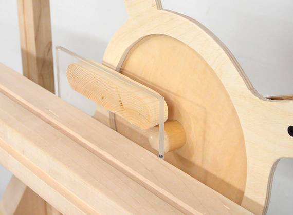
I didn't make the chain totally taut, so there was some wiggle room when the chain link
with the hook on it is between the sprockets. I added a bearing to the shaft
and blocks of wood to constrain it to a straight line.
It's a bit tricky to get everything together. With the pantograph links in place,
I put the bearing on the shaft, then put the shaft in the chain link.
Another piece of plywood goes against the pantograph links in the back,
making sure that the shaft will not pop out of the chain.
It also helps to make sure the pantograph is vertical.
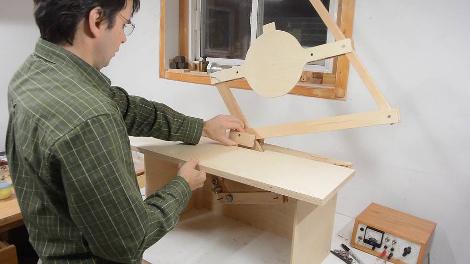
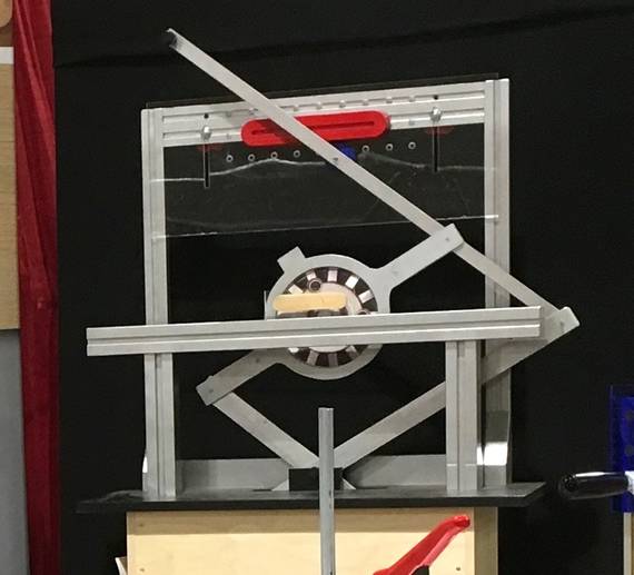
First test, with a "tenon" template. I put a 1" piece of dowel in the
middle of the router link to represent the router bit. By this time, I
had also cut out the middle of the router mount link and glued a very thin
piece of plywood to the back. This makes it look more like the
real pantorouter, but more importantly, it makes it lighter.
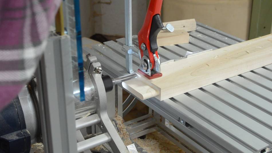
Next I needed some sort of template holder. I used my pantorouter to make mortise and
tenon joints to put it together, naturally!
I cut a 10 mm wide groove along the pieces for the template holder to make them look
more like the aluminium extrusions of the template holder on the actual metal
pantorouter.
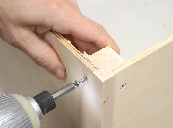
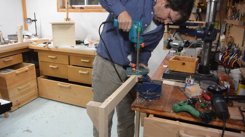
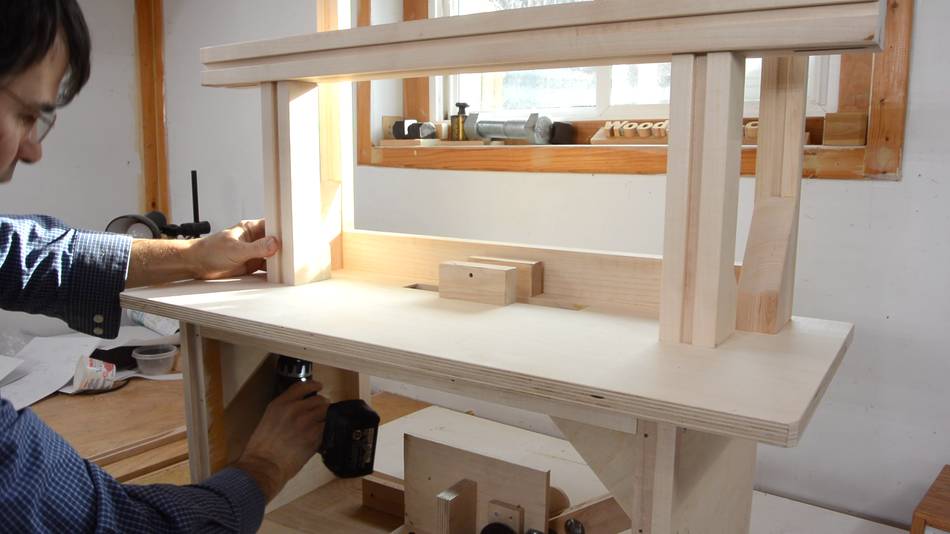
The template holder is attached with bolts from below the table. I figured using threaded
inserts and 5/16" hex bolts was a good way to make it easy to disassemble the machine.
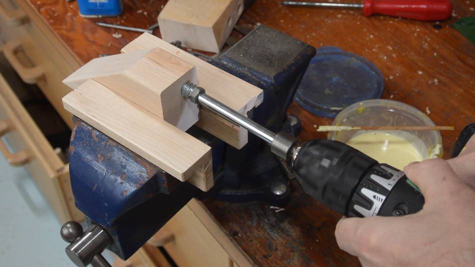
Just for good measure, I put some glue in the holes that I put the threaded inserts in, then
installed the inserts by driving them in with a long bolt
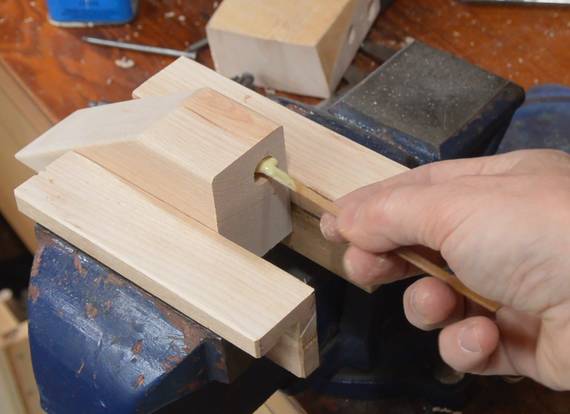
I decided to add more threaded inserts to the template frame after I glued it
together, so I had to do that in my vise.
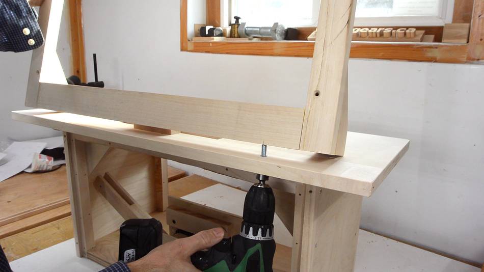
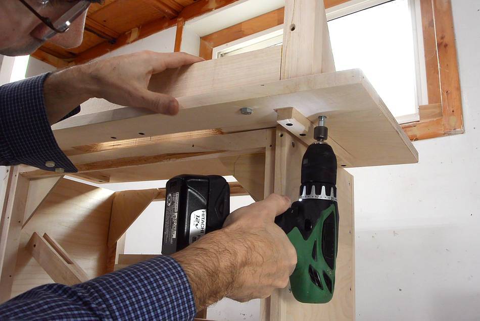
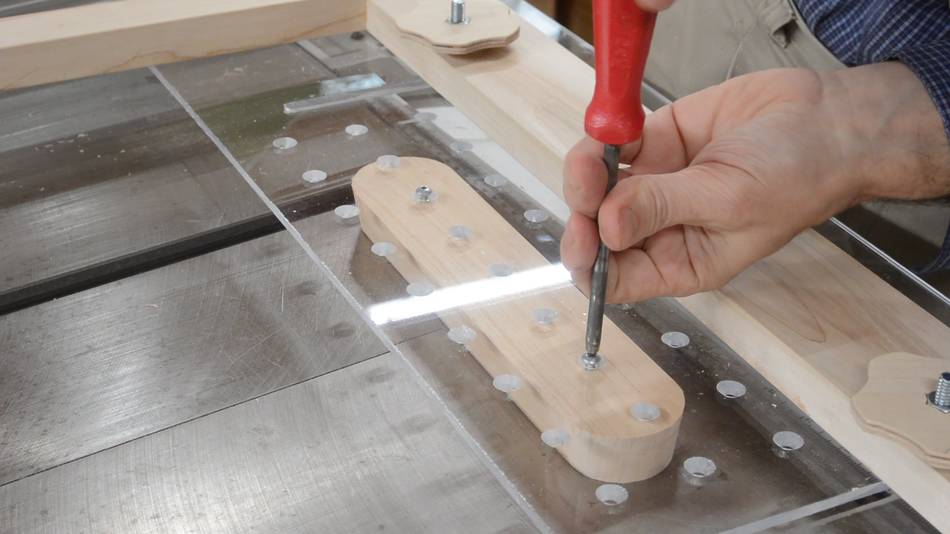
Now installing the template holder. I used a 1/2" nut driver in a drill to
drive the bolts in — quicker that way.
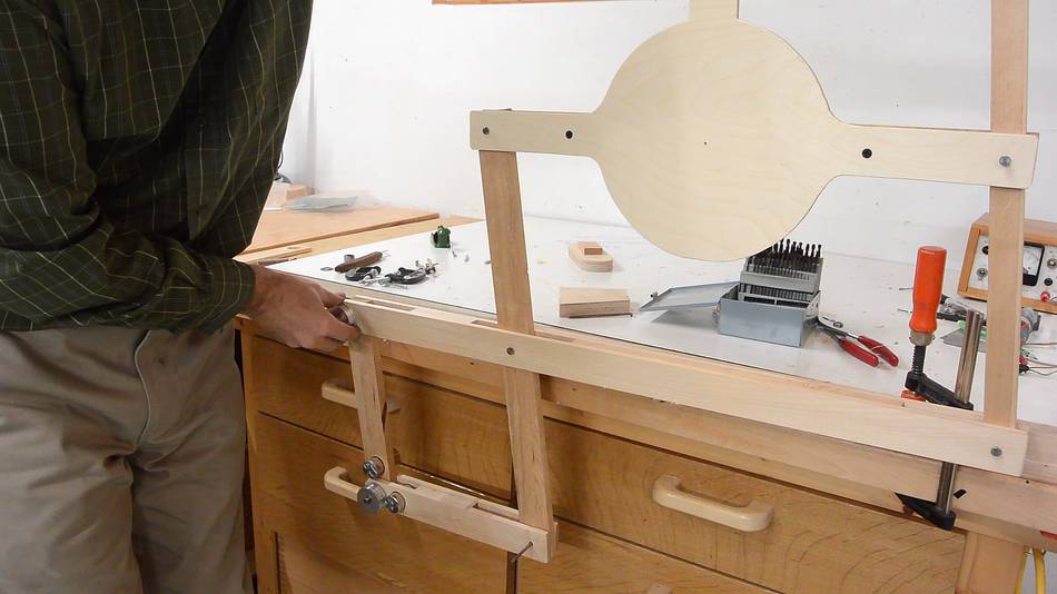
The "table" that goes in front of the pantograph is attached the same way.
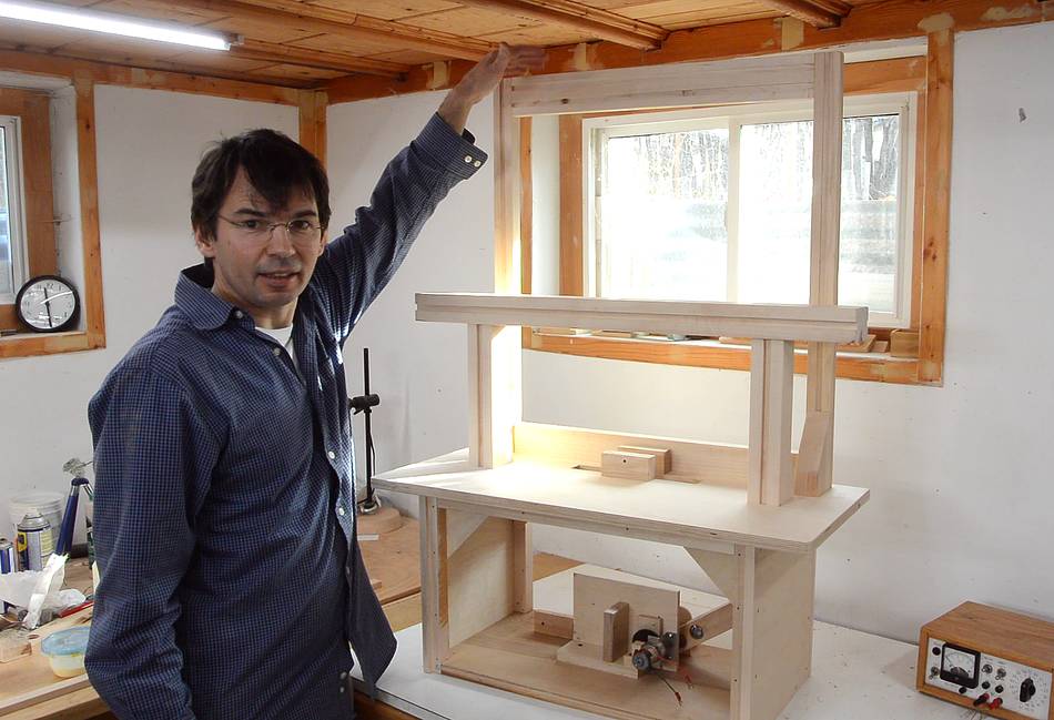
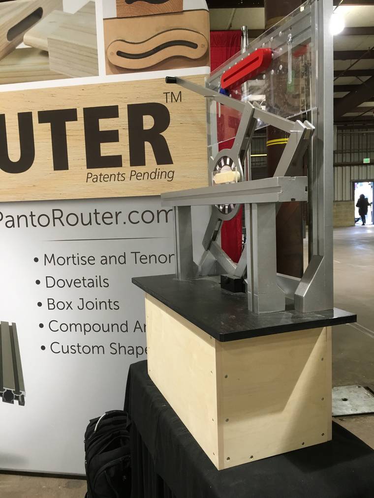
The whole thing is over 1 meter tall, and getting close to the ceiling in
my workshop.
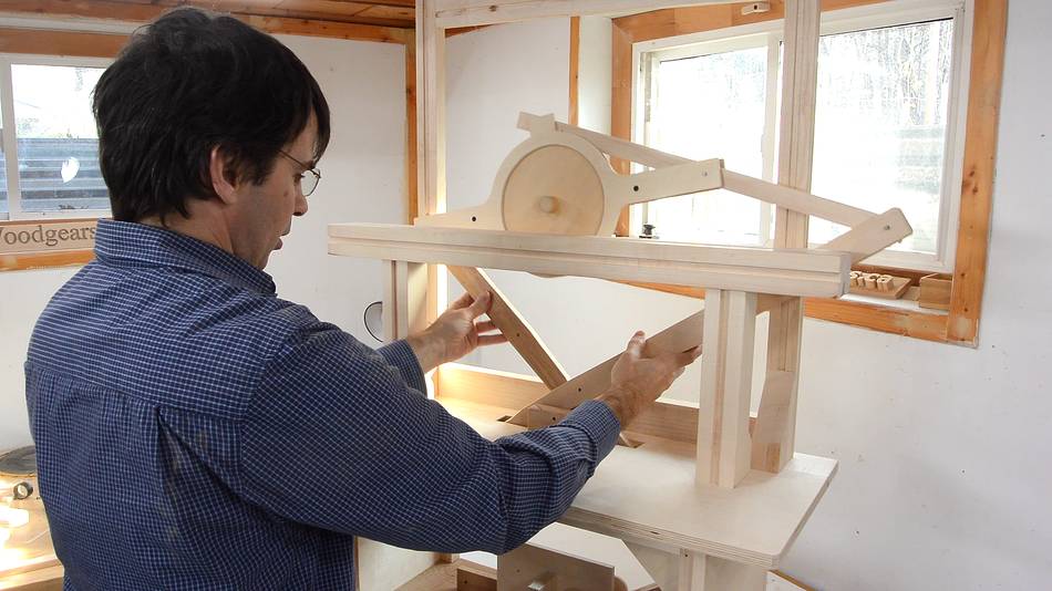
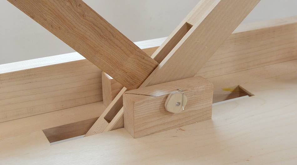
The pantograph installs in a slot in the table. Slightly tricky to get it in.
After that, I have to put pins in to connect it to the links that are connected
to the chain drive.
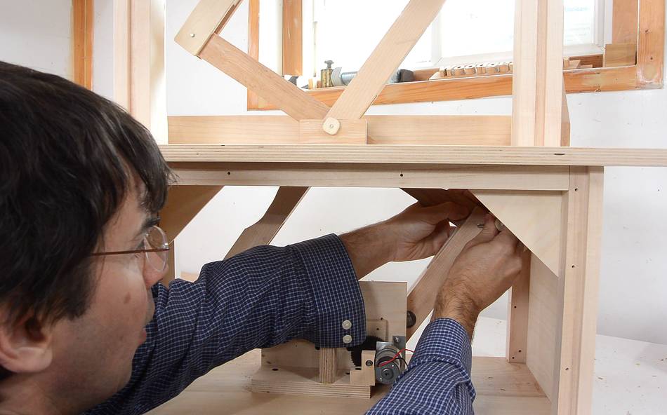
The pins for the lower link and main pivot have to be insertable by hand.
This means there is a risk that they might work themselves loose
over time.
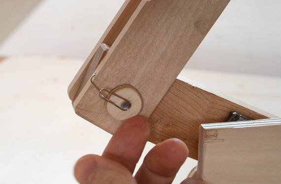
I drilled some very small holes in the links next to the pins and used paper clips
to hook the pins in place. The pins have flat plywood knobs on them and the
paperclip hooks to that.
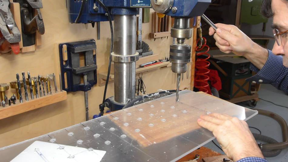
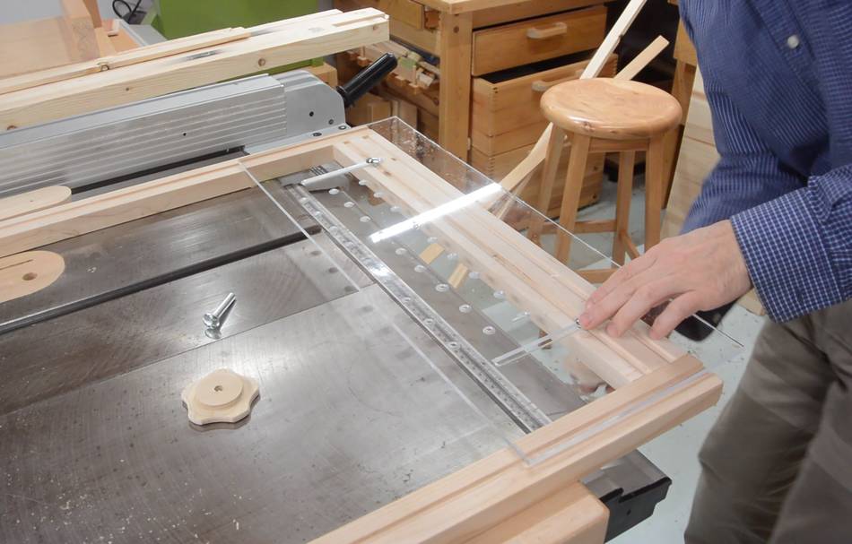
I needed something to hold the template to the template holder frame. I figured, I might
as well make this look like the template holder on the actual pantorouter. So I bought
a piece of acrylic plastic and drilled a grid of holes in it, just like on the
actual machine.
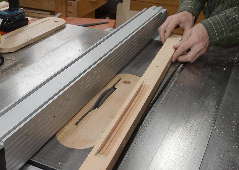
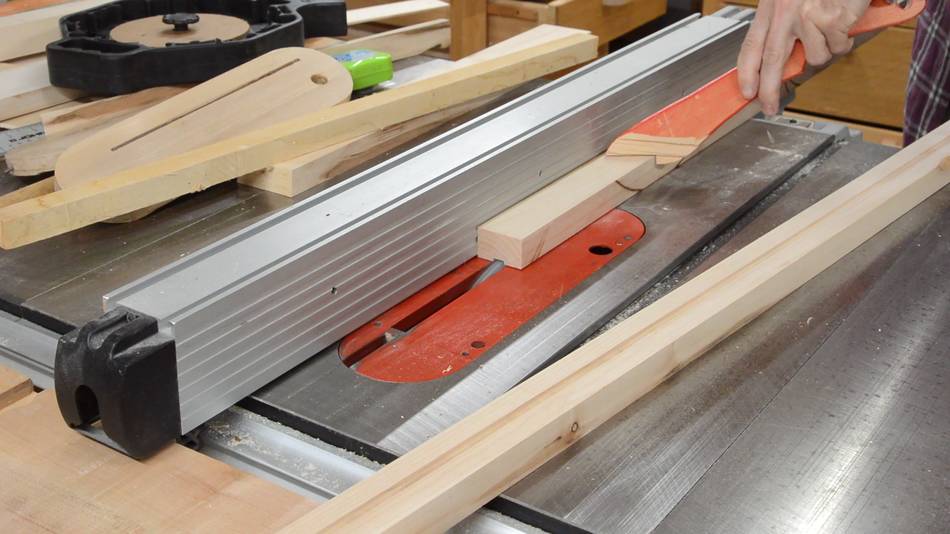
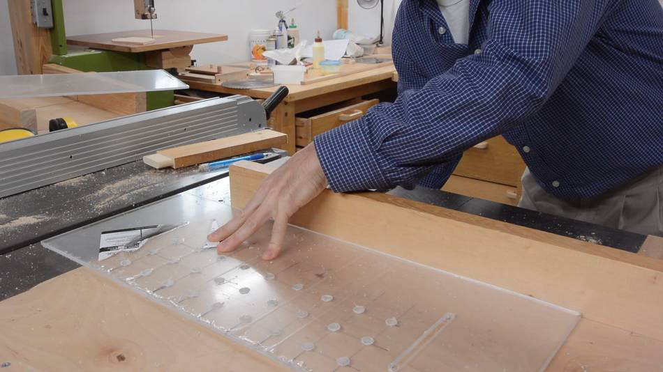
I cut the slots for the vertical adjustment by raising a small blade through it (a plunge cut)
on my table saw.
I made some wooden knobs the same shape as the ones to hold the template on the real one.
The knobs and some 5/16" carriage bolts hold the acrylic panel.
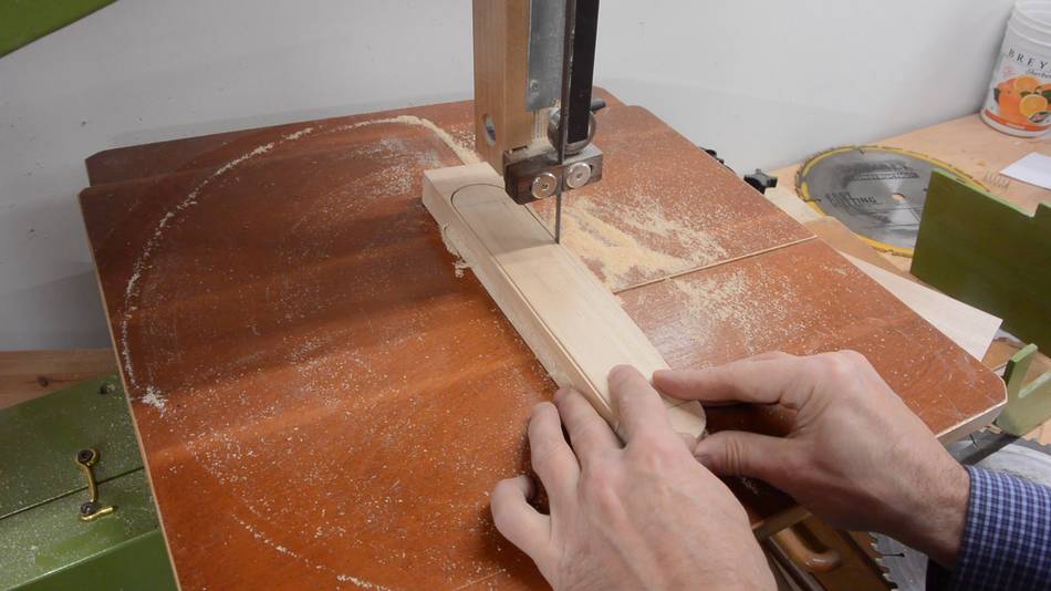
Next, an actual "template". I cut this out of a piece of hardwood, tilting the bandsaw table
slightly as I cut to make it tapered.
The template screws to the template holder from the back.
Then installing it.
I also made a wooden "follower bearing".
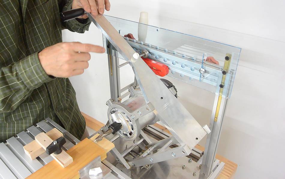
I tested the whole thing on my workbench. I had to make a shorter version of the
"operating lever", because the handle extension kept hitting the ceiling.
I also made a tenon to go on the "table". The tenon is glued to some acrylic using
a transparent glue, so seen from the front there is just wood grain.
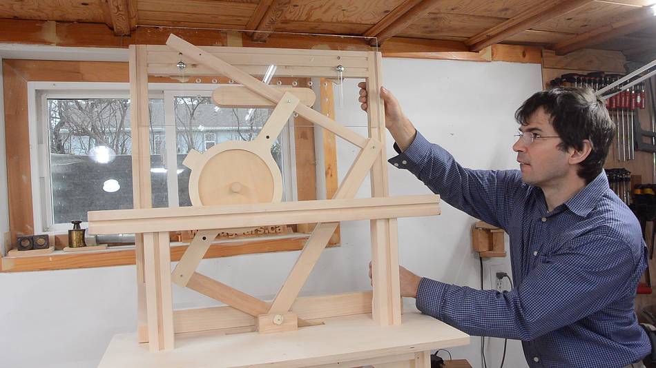
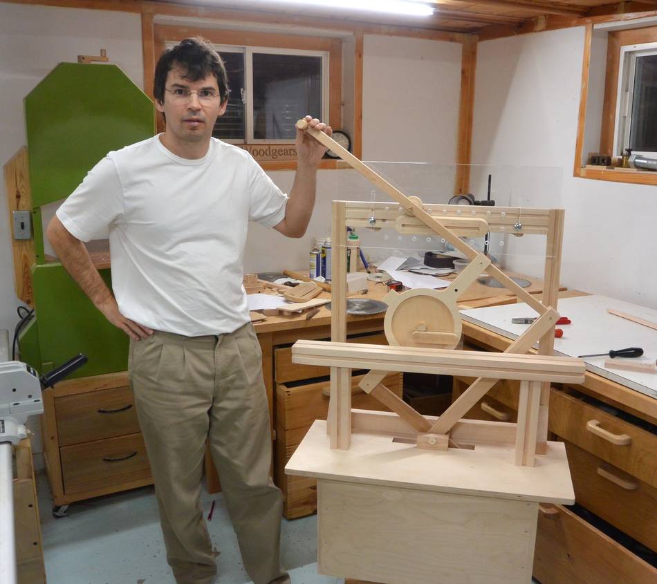
Finally, I moved the whole set-up off my workbench so I could use the full length
operating lever. The bigger lever unfortunately necessitated even more counterweights
on the bottom.
The pantograph is scaled up two times from the actual machine. A pantograph
that size can quickly become unwieldy!
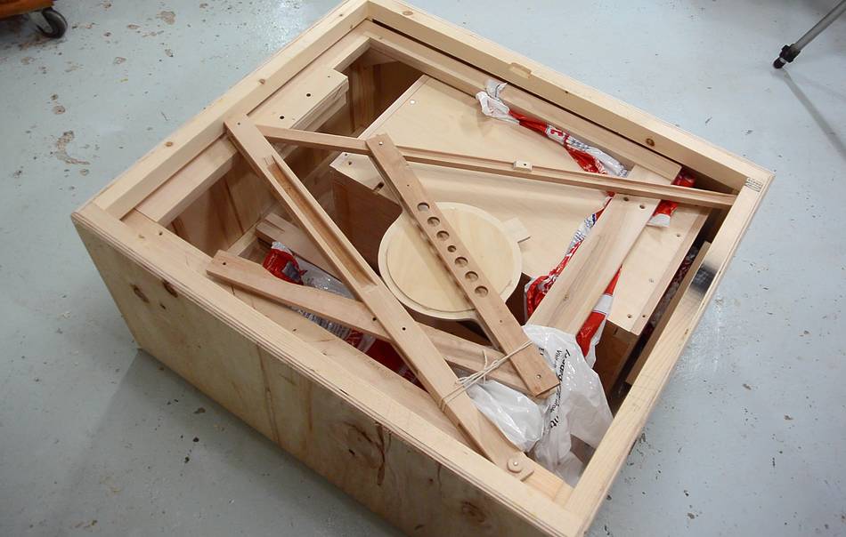
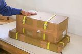
Finally, disassembling it and cramming the whole thing into a
shipping crate that
I made specially for it. I was just barely able to fit all the pieces into the box.
Luckily, I was able to get the pantograph part in without taking the tightly
fitting pins out.
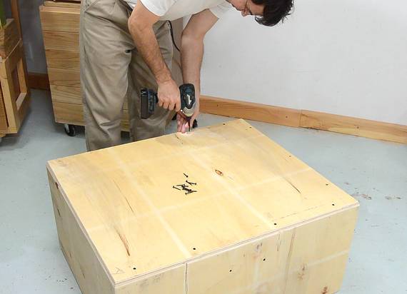
Then screwing the lid on, and shipping it off.
I was only too happy to finally get it out of my shop!
This project was way more work than I planned on and dragged on over the course
of two weeks. It also ended up taking way more effort than Mac Sheldon had
anticipated. After it shipped, I looked at Mac's original email again.
How did this thing get so complicated? Well trying to make something that works
smoothly in my absence is difficult, and requires that it is well built.
Some of the touches, like the acrylic plastic template holder, or the nice
hardwood table were not necessary. But putting a bit of extra effort into it to
make it look more like the real thing was an incremental effort on the
whole thing.
In the end, I don't think the level of effort was fully justified by the need.
Still I can't think of a quick and dirty way of doing it
that would have looked good and worked well. If I was faced with the request
again, I would do what I always do and decline it. Lesson learned!
Update (Dec 20 2015):
Mac sent me a video (at left) that he shot when he recieved it.
Shot upright on a cellphone, so it's in "portrait" format.
Update (Jan 14 2016):
Mac completely disassembled the pantograph mechanism for painting and only reassembled
it on the tradeshow floor. He mentioned "it didn't go flawlessly due to my mistake
in resembling after painting the parts". No surprise there, I'd put it together backwards
a few times myself!
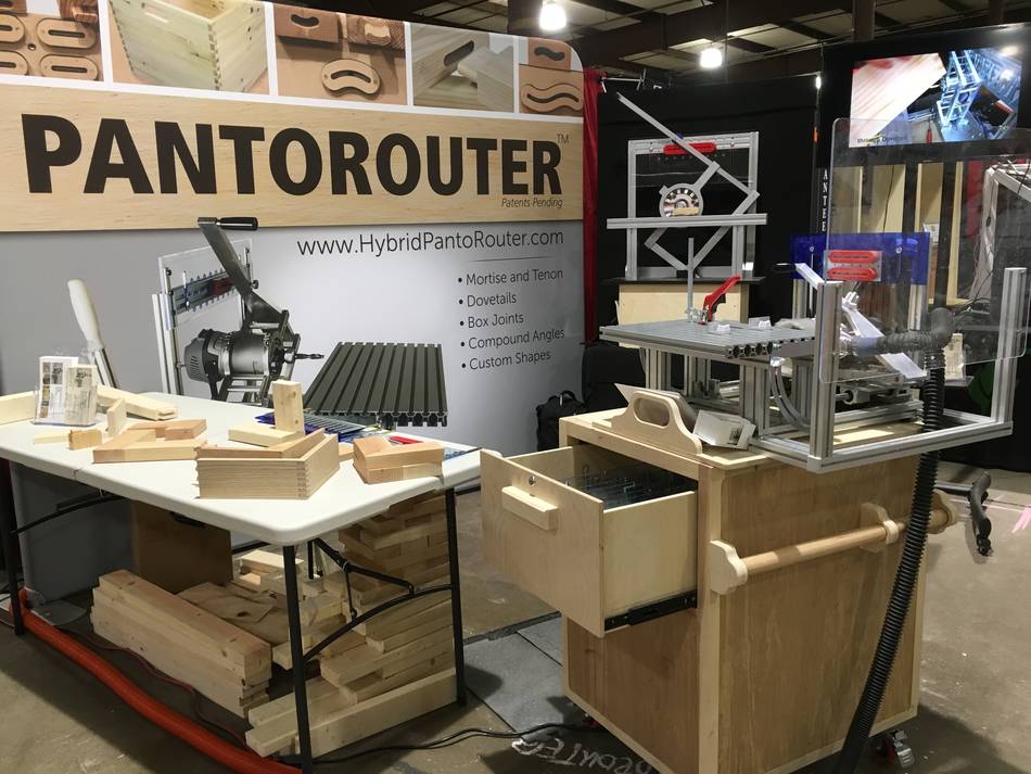
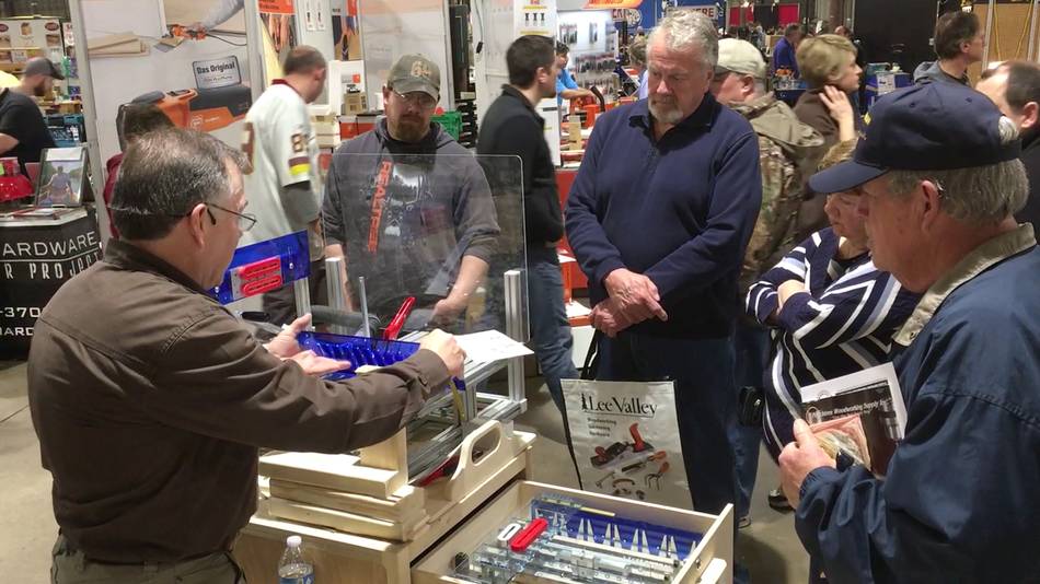
He had the demo running for three days non stop. I'm pleased
that it didn't break. I only ran it for maybe 30 minutes total during testing!
Mac says:
"I lost track of the number of people who came to the booth and told me
they watched the video of the demo and box builds. Dozens! Several
people told me they were unaware of the show until they saw the
announcement on Matthias' video and site."
Another video from the Baltimore wood show, this one with much better sound, recorded by
Mikhail Makarevich.
I recorded an introduction for him.
I still have a hard time believing my animated display machine worked the whole
length of the show (and still works as far as I know). You can see
people taking down the displays in the background in part of the video, and the machine is
still running!
 Mac Sheldon has started
distributing
the pantorouters made by Kuldeep.
He wanted a display showing a scaled-up animated pantograph to demonstrate how following
the template can be used to cut a tenon. He asked me if I could build such a thing
so he could show it at the wood show in Baltimore, Jan 2016.
Mac Sheldon has started
distributing
the pantorouters made by Kuldeep.
He wanted a display showing a scaled-up animated pantograph to demonstrate how following
the template can be used to cut a tenon. He asked me if I could build such a thing
so he could show it at the wood show in Baltimore, Jan 2016.
 Kuldeep's pantorouters
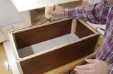 Recycled plywood box
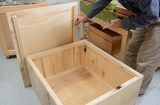 Shipping crate
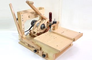 The pantorouter
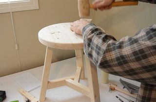 Building a 3-legged stool
 Designing segmented Knapp-joint pantorouter templates
 Hose cuff twisting on machine