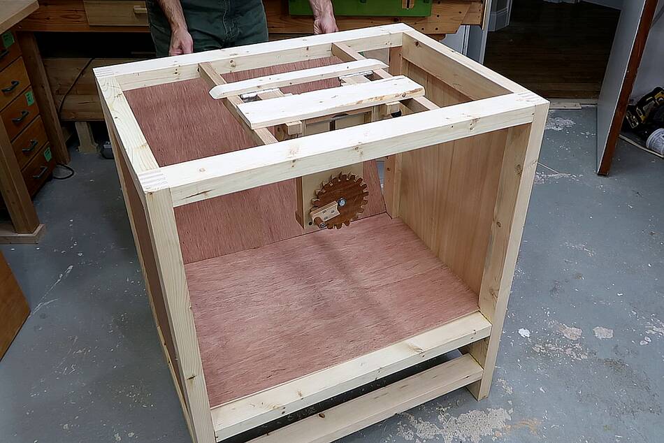
 I already built the cabinet for my router table.
The next step was building the integrated dust collection.
I already built the cabinet for my router table.
The next step was building the integrated dust collection.
I already built the cabinet for my router table.
The next step was building the integrated dust collection.
For this I need to build another blower. I've built quite a few similar blowers before:
Blower impeller design experiments (2017)
Blower housing shape experiments (2017)
Wet rotor synchronous dishwasher motor blower (2018)
Mini dust collector (2016)
Dust collector v1 blower (2012)
Dust collector v2 blower(2014)
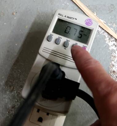
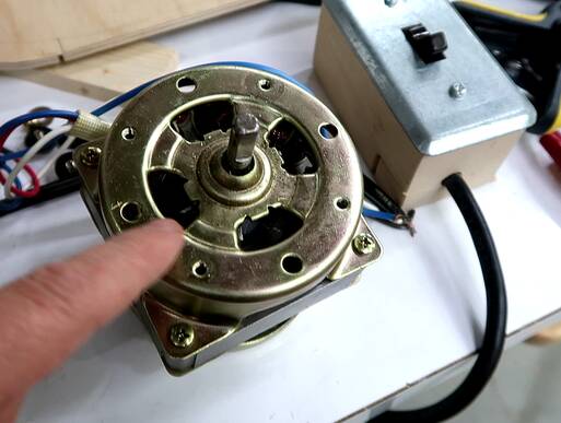
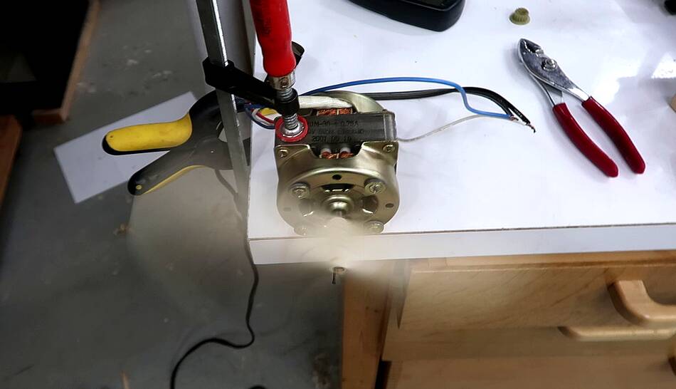 Going through my motors, the most suitable one I found was this
one from a bread maker. It's unfortunately only a 1700 RPM motor and a
bit smaller than I would like. It's rated to draw just 0.75 amperes.
Going through my motors, the most suitable one I found was this
one from a bread maker. It's unfortunately only a 1700 RPM motor and a
bit smaller than I would like. It's rated to draw just 0.75 amperes.
The first thing to do is to figure out how big an impeller I can spin with it. I mounted a paddle on the shaft and shortened it until the motor consumed it's rated current (the only spec I have for the motor). The length and width of the paddle correspond to how large an impeller I can spin with it. It's a useful rule of thumb I figured out years ago when I built this blower in 2014.
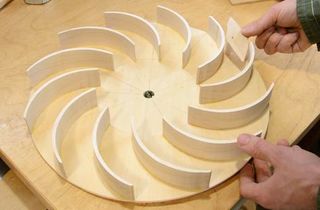
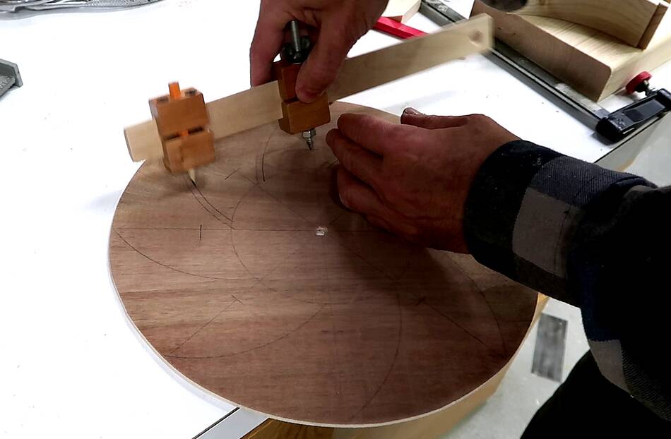 I laid out the impeller to have eight blades. Eight is a good number
and easy to lay out with a square and 45° square.
I laid out the impeller to have eight blades. Eight is a good number
and easy to lay out with a square and 45° square.
I arbitrarily picked the radius for the blades to what seems intuitively right. I want the outer tips of the blades to be near tangential to the circumference and the inner end to be near radial.
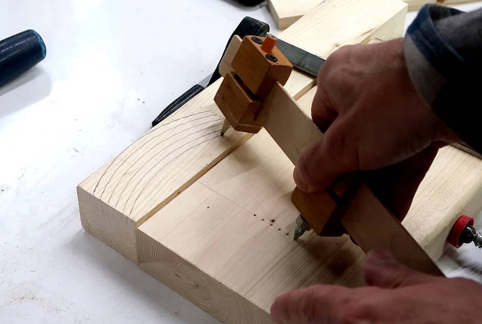
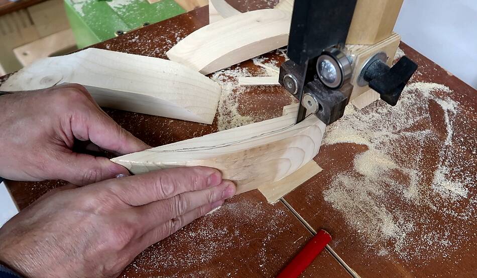
I drew arcs spaced 8 mm apart using my beam compass on a piece of 1.5" thick softwood as a guide for cutting the blade.
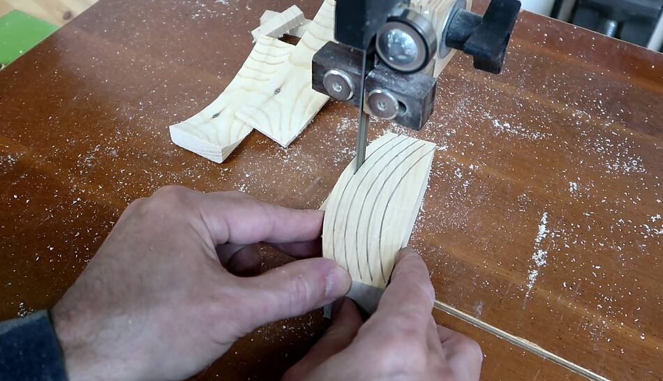 Then cut the arcs with a bandsaw to cut out the blades.
I sanded both edges of the blades smooth after that.
Then cut the arcs with a bandsaw to cut out the blades.
I sanded both edges of the blades smooth after that.
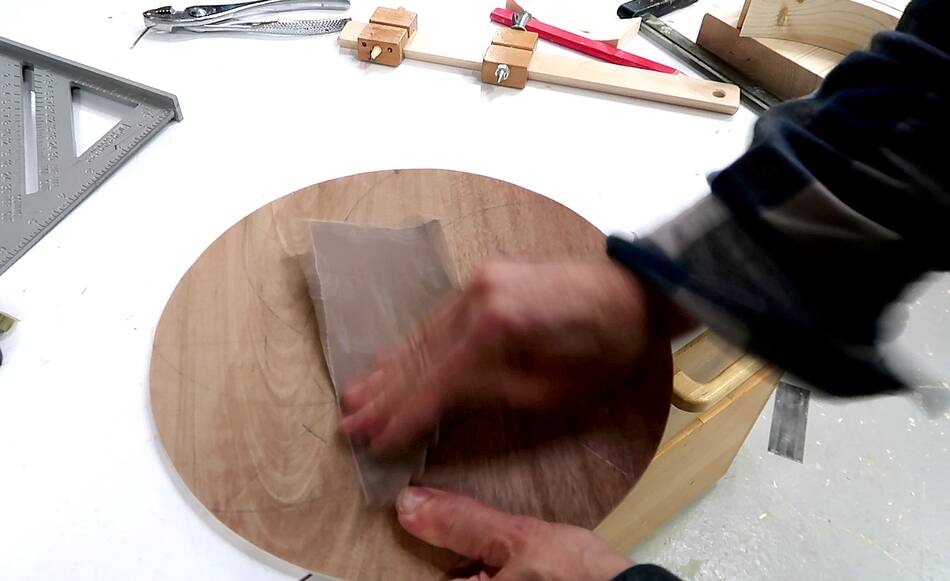 Before gluing on the blades, I gave the plywood a light sanding. Surfaces
exposed to the air accumulate a microscopic layer of atmospheric grime over
time, and it's better to sand that off before gluing.
Before gluing on the blades, I gave the plywood a light sanding. Surfaces
exposed to the air accumulate a microscopic layer of atmospheric grime over
time, and it's better to sand that off before gluing.
 I also realized the plywood I was using wasn't completely flat. I could rock
it back and fort on a flat surface. So I needed to clamp that plywood
to a thicker flatter piece of plywood while gluing.
I also realized the plywood I was using wasn't completely flat. I could rock
it back and fort on a flat surface. So I needed to clamp that plywood
to a thicker flatter piece of plywood while gluing.
 I started by gluing the blades down with clamps, but then decided that light
pressure applied with weights is probably better, so I moved the clamps
to press down just the plywood backer and used weights to press on the blades.
I started by gluing the blades down with clamps, but then decided that light
pressure applied with weights is probably better, so I moved the clamps
to press down just the plywood backer and used weights to press on the blades.
A thin layer of glue between pieces of wood makes a stronger bond, and clamping too hard can make the joint slightly glue starved. That said, it's hard to over clamp a joint, but as long as the gap is full of glue, a small sub-millimeter gap certainly doesn't hurt.
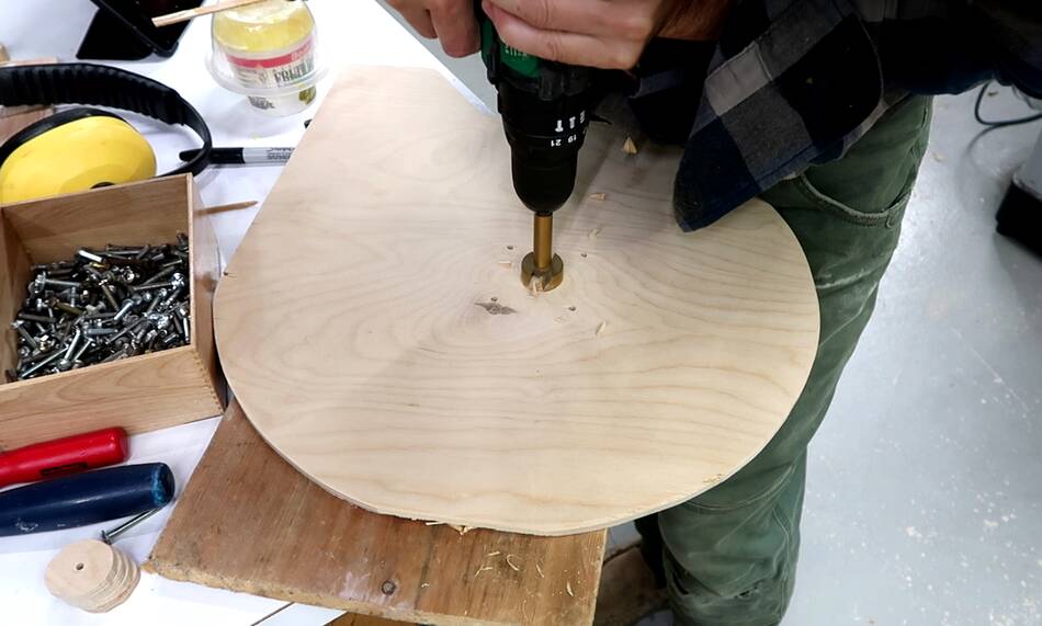
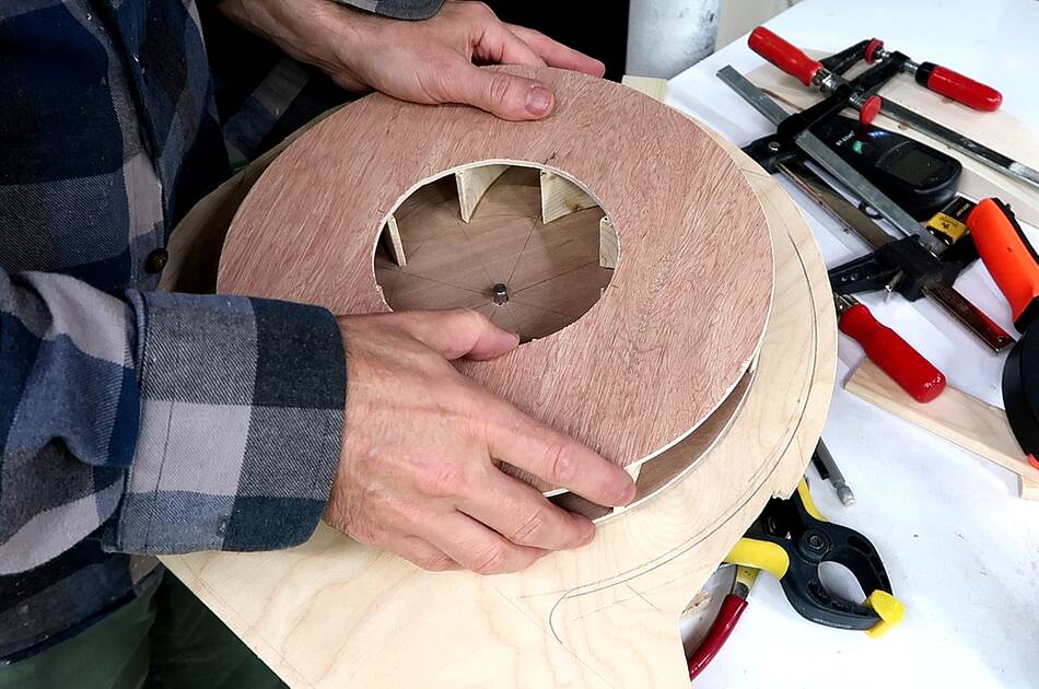
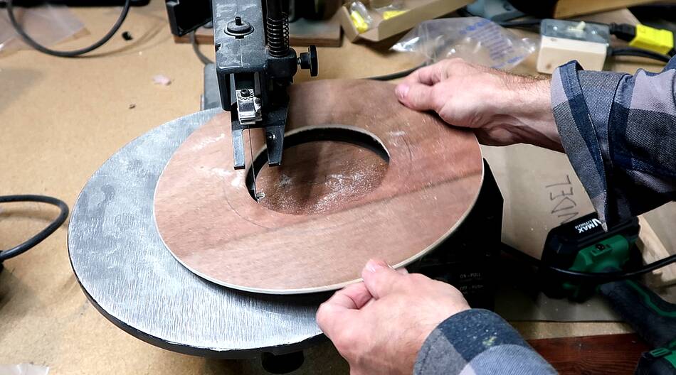 Then cutting a hole for the front rotor disc. Aside from making the rotor
stronger, the front disc also makes the rotor more efficient as it cuts down on
air looping back to the middle in front of the rotor.
Then cutting a hole for the front rotor disc. Aside from making the rotor
stronger, the front disc also makes the rotor more efficient as it cuts down on
air looping back to the middle in front of the rotor.
I use my scrollsaw for that because it's an inside hole. Cutting holes like that is the only thing I use my scrollsaw for.
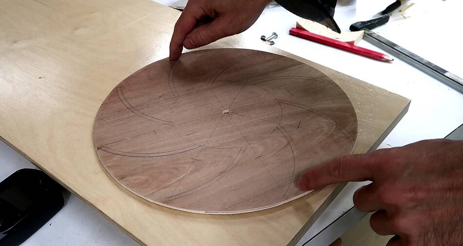
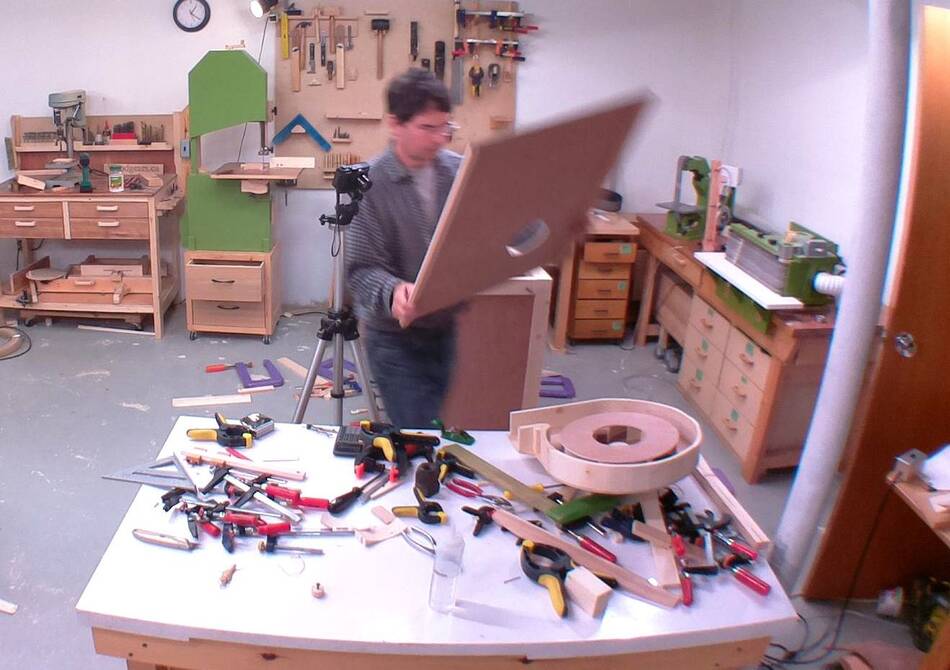
 I laid out the shape of the housing. Initially I wanted to trace the volute shape
by wrapping a string around a round peg and have that guide a pencil, but
the scrap of plywood I wanted to use was a bit on the small side, so I had to be
careful to make that fit. I ended up drawing a bunch of 90 degree arcs to approximate
the volute like I usually did in the past.
I laid out the shape of the housing. Initially I wanted to trace the volute shape
by wrapping a string around a round peg and have that guide a pencil, but
the scrap of plywood I wanted to use was a bit on the small side, so I had to be
careful to make that fit. I ended up drawing a bunch of 90 degree arcs to approximate
the volute like I usually did in the past.
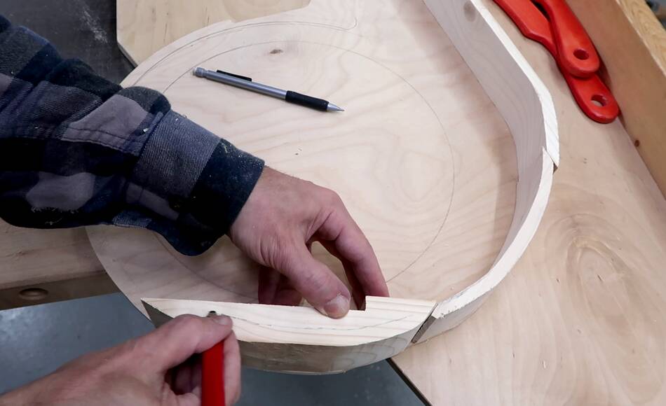
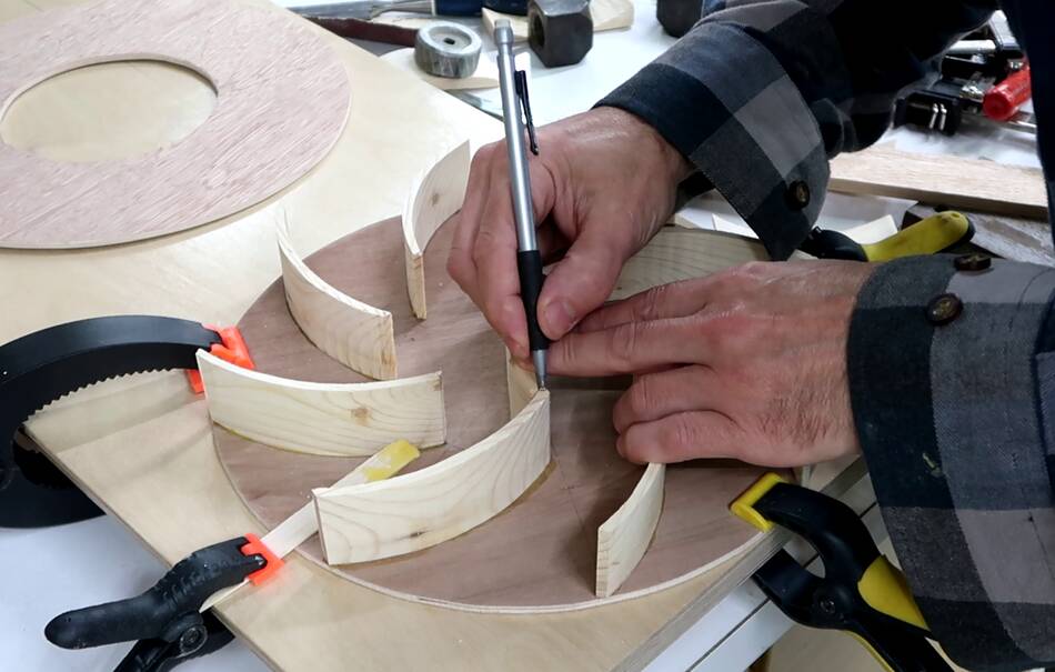
I then cut that out with the bandsaw, then cut pieces of wood to match the outside contour and traced for about 15 mm width with a pencil...
 ... then cut the inside curve on the bandsaw. Then sanding everything.
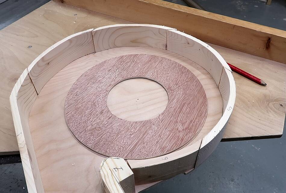 Pieces laid out on the plywood, not glued on, but numbered so I wouldn't end up
mixing them up.
Pieces laid out on the plywood, not glued on, but numbered so I wouldn't end up
mixing them up.
From this experiment I knew the exact housing shape mattered surprisingly little as long as it's big enough, It's good to have a bit of room around the impeller. More room makes it quieter and slightly improves the suction because some air around the rotor will spin with the rotor, and centrifugal force on that air adds to the pressure (or suction).
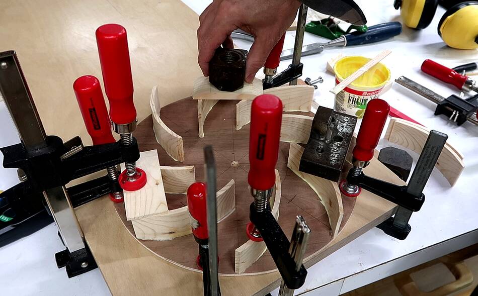
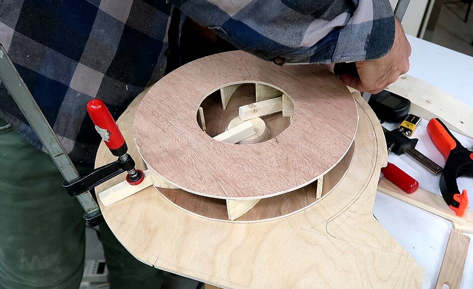
 I carefully transferred the inner circle of my impeller layout to the top
of the impeller blades to serve as a guide for getting the top layer on center.
I carefully transferred the inner circle of my impeller layout to the top
of the impeller blades to serve as a guide for getting the top layer on center.
In the past, I misaligned the top layer by as much as 2 mm. The hole being off center isn't a problem for airflow, but it means a lot of balancing needs to be done.
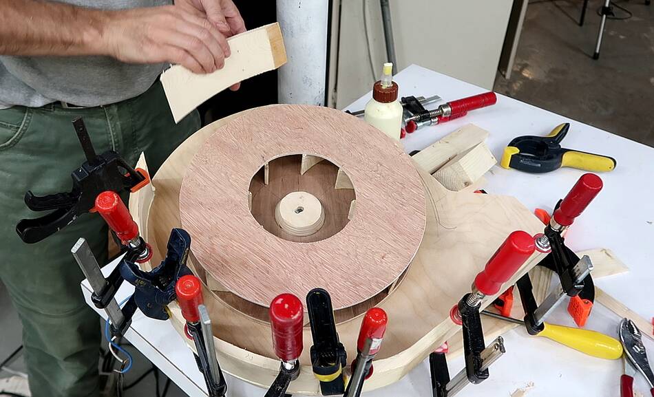
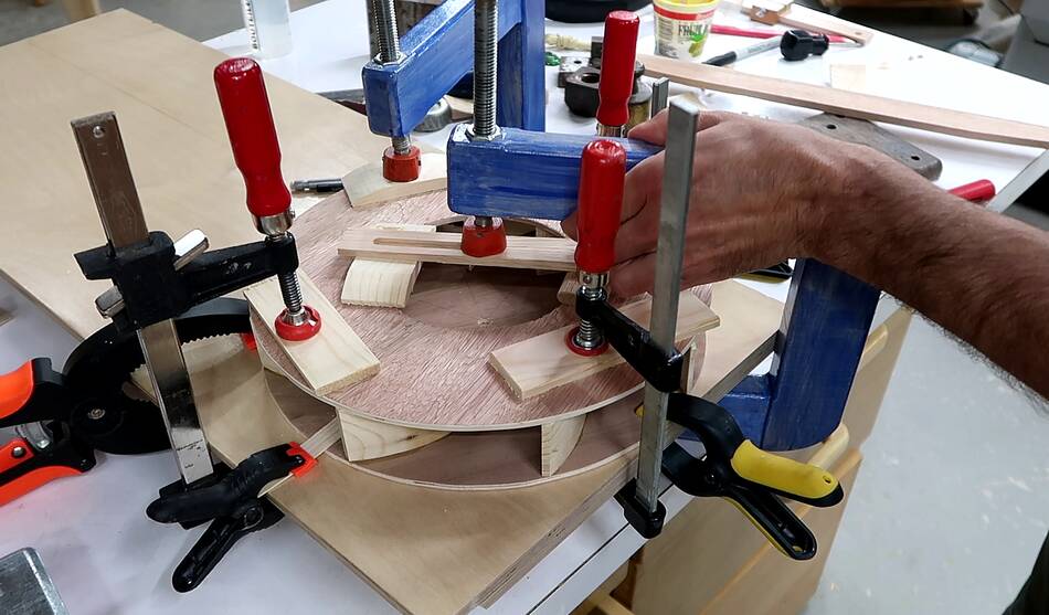 Clamping on the top layer. The top layer also wasn't completely flat so
I needed clamps to make sure it fit the rotor. I figure with the whole
sandwich being flat while clamped, it will stay flat once glued together.
Clamping on the top layer. The top layer also wasn't completely flat so
I needed clamps to make sure it fit the rotor. I figure with the whole
sandwich being flat while clamped, it will stay flat once glued together.
I used to worry that a rotor like that would explode from spinning, but I've been using quite a few blowers like that for many years now and none ever failed.
Also, this one is only 1700 RPM, which means the forces on it are only a quarter what they would be for a 3500 RPM blower.
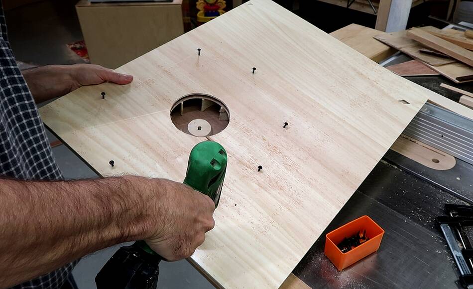
 Then working on the motor mount, before gluing the housing together.
The motor has mounting holes on the front, but only a short shaft.
 I glued some pads where the motor mount to offset it from the panel
a little bit. That way the front of the motor is not cut off from air
circulation.
I glued some pads where the motor mount to offset it from the panel
a little bit. That way the front of the motor is not cut off from air
circulation.
 I also drilled some shallow holes for the screw heads in the front so the
screws would not protrude out of the plywood. The pads on the back help
to reinforce the plywood where I thinned it with the holes for the
screw heads.
I also drilled some shallow holes for the screw heads in the front so the
screws would not protrude out of the plywood. The pads on the back help
to reinforce the plywood where I thinned it with the holes for the
screw heads.
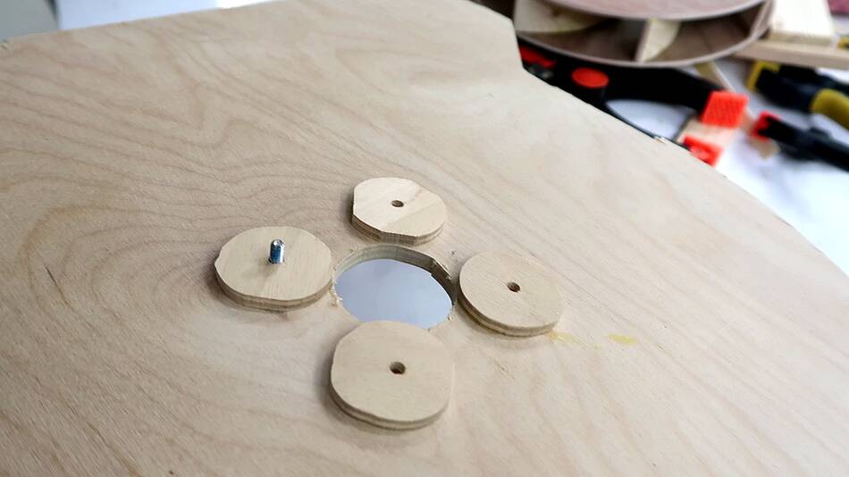
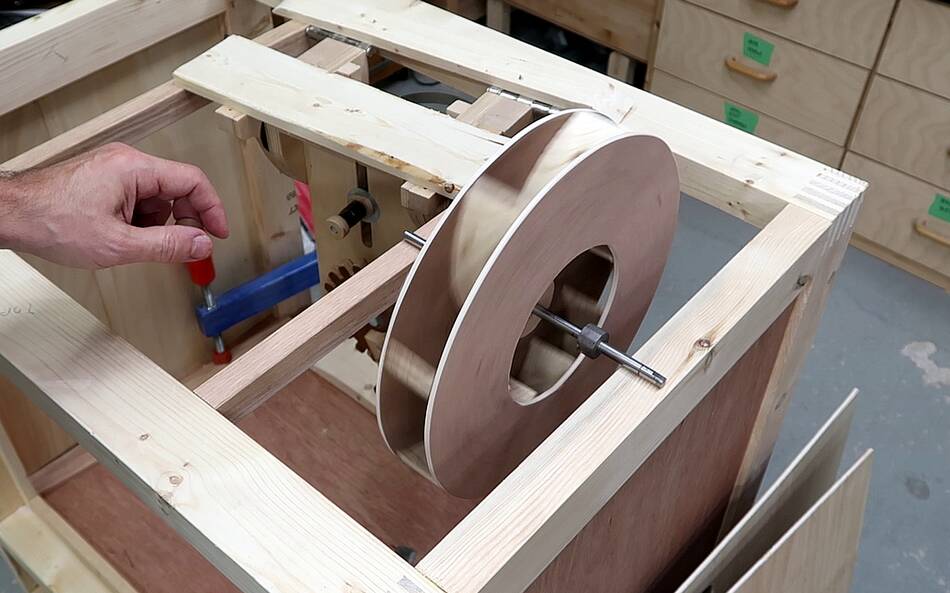
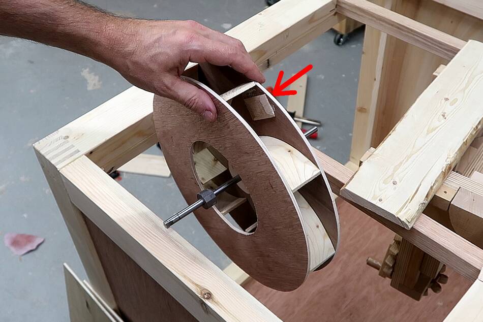
 Then fitting the rotor. I added a 6 mm thick piece of plywood to the
back to help reinforce where the shaft goes (not visible in this picture).
Then fitting the rotor. I added a 6 mm thick piece of plywood to the
back to help reinforce where the shaft goes (not visible in this picture).
 And another 12 mm thick piece of plywood on the front to engage more of
the motor's shaft. I glued that piece in place with the rotor on the
motor and clamped against the housing. This way I could ensure the rotor
wasn't on crooked.
And another 12 mm thick piece of plywood on the front to engage more of
the motor's shaft. I glued that piece in place with the rotor on the
motor and clamped against the housing. This way I could ensure the rotor
wasn't on crooked.
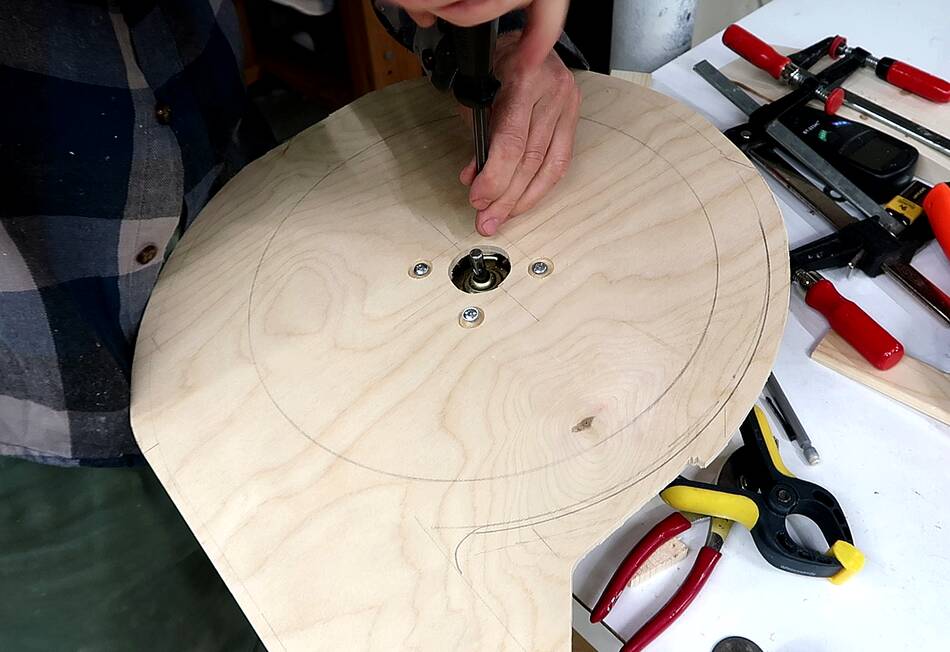
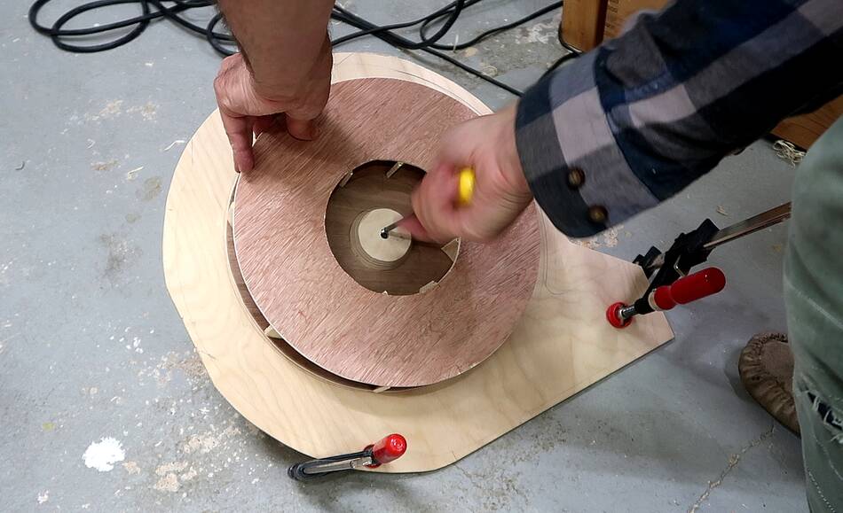 I tested it with the rotor, but the motor's shaft ended up spinning
in the hole in the rotor. So it definitely needed locking on. I
filed a notch in the side of the hole, then put a 1" long #4 screw
into the notch, facing the flat key side of the motor shaft. This locks
the rotor onto the motor.
I tested it with the rotor, but the motor's shaft ended up spinning
in the hole in the rotor. So it definitely needed locking on. I
filed a notch in the side of the hole, then put a 1" long #4 screw
into the notch, facing the flat key side of the motor shaft. This locks
the rotor onto the motor.
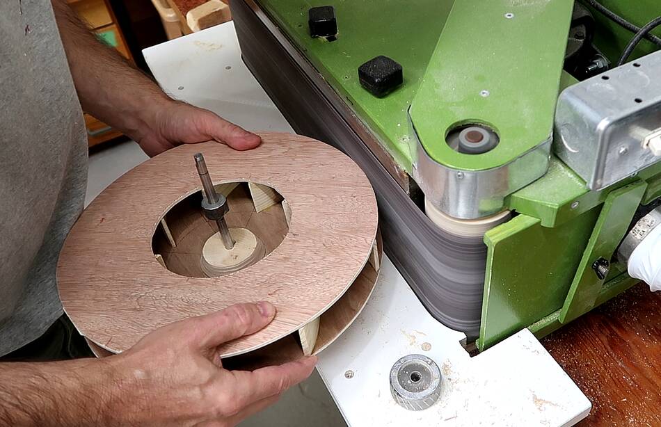
Testing it again, there was quite a lot of vibration. The rotor definitely needed balancing
 I put an 8 mm shaft through the rotor and spun it between two
horizontal pieces of wood. While I was pleased how little side-to-side
wobble the rotor has, its definitely heavier on on one side.
I put an 8 mm shaft through the rotor and spun it between two
horizontal pieces of wood. While I was pleased how little side-to-side
wobble the rotor has, its definitely heavier on on one side.
 I sanded down the heavy side some, but it wasn't enough to balance it.
 So I glued another piece of wood to the inside of the rotor to add weight
to the light side. This got the balance close enough.
So I glued another piece of wood to the inside of the rotor to add weight
to the light side. This got the balance close enough.
I later balanced it some more
 With the rotor and motor still mounted on the back of the blower housing
from my previous test, I glued the outside of the housing on.
With the rotor and motor still mounted on the back of the blower housing
from my previous test, I glued the outside of the housing on.
 To save plywood, I figured the back panel of the cabinet would also serve
as the front of the blower.
To save plywood, I figured the back panel of the cabinet would also serve
as the front of the blower.
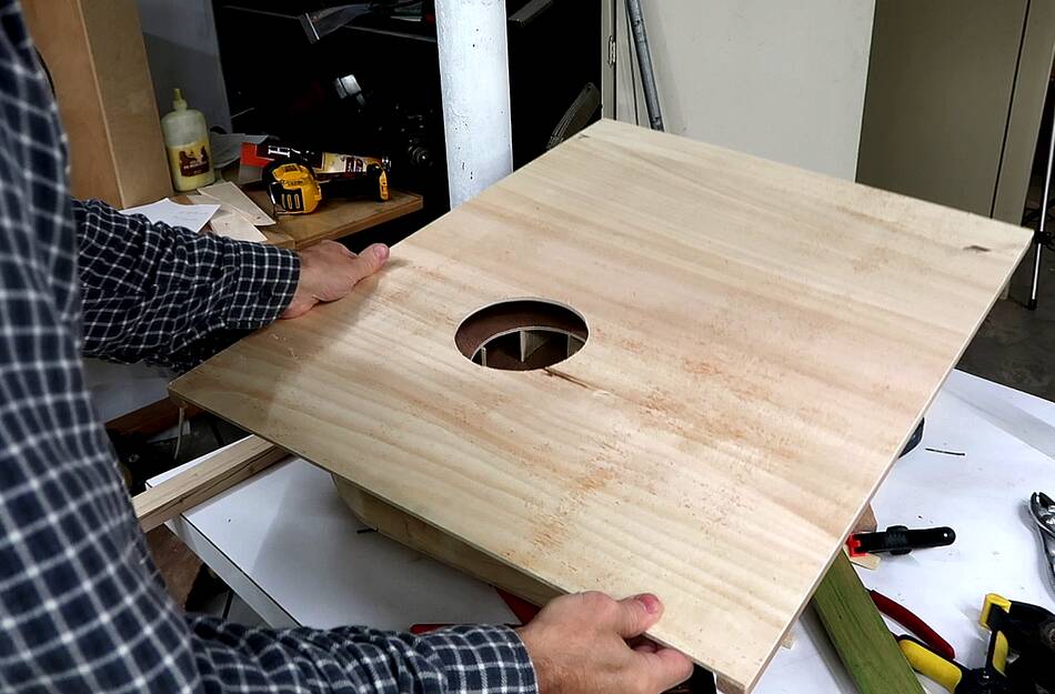 With a hole cut in the right place in the cabinet back panel, I just
clamped it to the front of the blower for testing.
With a hole cut in the right place in the cabinet back panel, I just
clamped it to the front of the blower for testing.
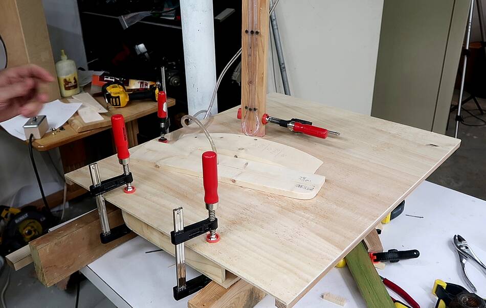
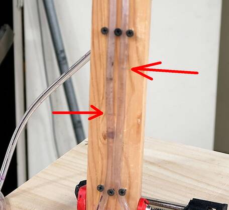 Testing static suction with a U-shaped hose with water in it as a manometer.
I only got about 5 cm of head. But with only a 1700 RPM motor I wasn't
expecting much. Had this been a 3400 RPM motor, I would have had 20 cm of
head for suction, which would be about typical for shop dust collectors.
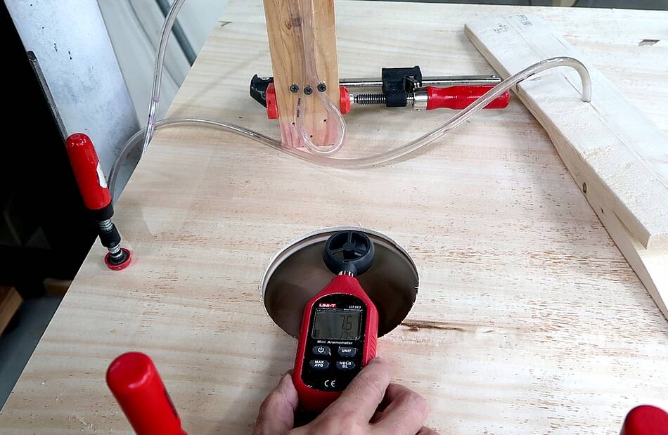 Testing air speed with an anemometer, I measured 7 meters per second over
the all of the 12 cm diameter hole. That worked out to .08 cubic meters
per second, or 4.7 m3/s or 167 CFM. But that's with just the
blower. Once it has to suck through a filter and through the top of the
cabinet, air resistance will reduce the flow somewhat.
Testing air speed with an anemometer, I measured 7 meters per second over
the all of the 12 cm diameter hole. That worked out to .08 cubic meters
per second, or 4.7 m3/s or 167 CFM. But that's with just the
blower. Once it has to suck through a filter and through the top of the
cabinet, air resistance will reduce the flow somewhat.
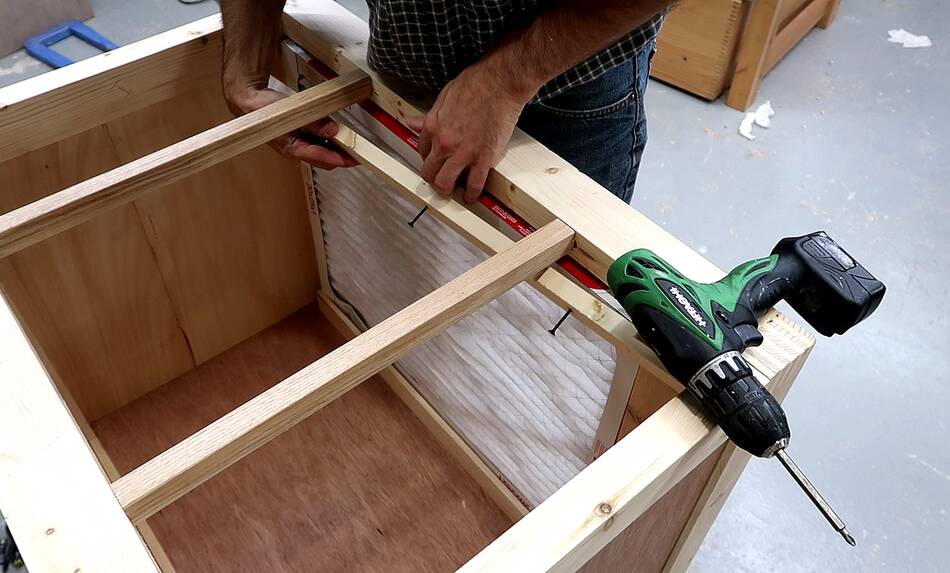 Mounting a furnace filter in the back of the cabinet. Furnace filters really
aren't meant to be used this way, but in time they will get caked with sawdust,
and it's the actual sawdust that will do the filtering. This process
is known as "seasoning" a filter. The sawdust on and in the filter media
makes for more air resistance but also improves how much of the fine dust
is filtered out of the air.
Mounting a furnace filter in the back of the cabinet. Furnace filters really
aren't meant to be used this way, but in time they will get caked with sawdust,
and it's the actual sawdust that will do the filtering. This process
is known as "seasoning" a filter. The sawdust on and in the filter media
makes for more air resistance but also improves how much of the fine dust
is filtered out of the air.
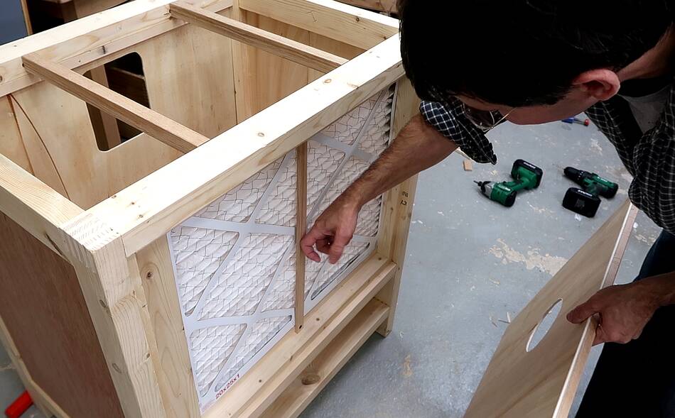 This vertical piece of wood against the filter will help to keep the
filter from bowing towards where the air is sucked out.
I only have about 3 cm or space behind the filter.
This vertical piece of wood against the filter will help to keep the
filter from bowing towards where the air is sucked out.
I only have about 3 cm or space behind the filter.
 Finally screwing the blower onto the back panel...
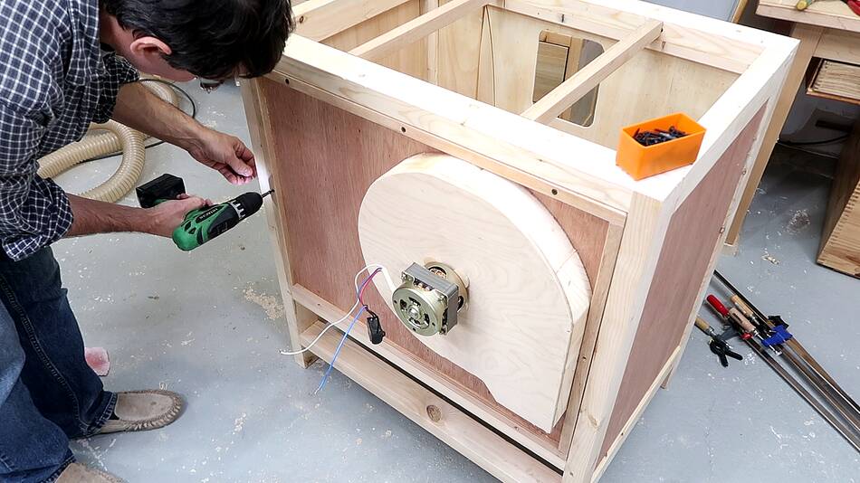 ... and mounting the back panel on the cabinet.
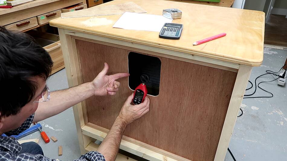 I measured the air speed over this opening at 3 meters per second.
Multiplying that by the area of the hole, that again came to 0.08
m3/s. The furnace filter is still clean so it doesn't
make for much air resistance.
I measured the air speed over this opening at 3 meters per second.
Multiplying that by the area of the hole, that again came to 0.08
m3/s. The furnace filter is still clean so it doesn't
make for much air resistance.
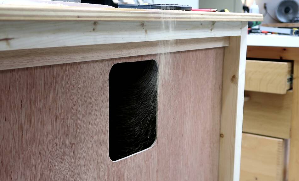 But the air speed was enough to suck sawdust dropped in font of the
hole into the hole as it fell past.
But the air speed was enough to suck sawdust dropped in font of the
hole into the hole as it fell past.
It's because this blower doesn't have to suck through a hose that its able to move as much air as it does, even though it produces very little static pressure (or suction).
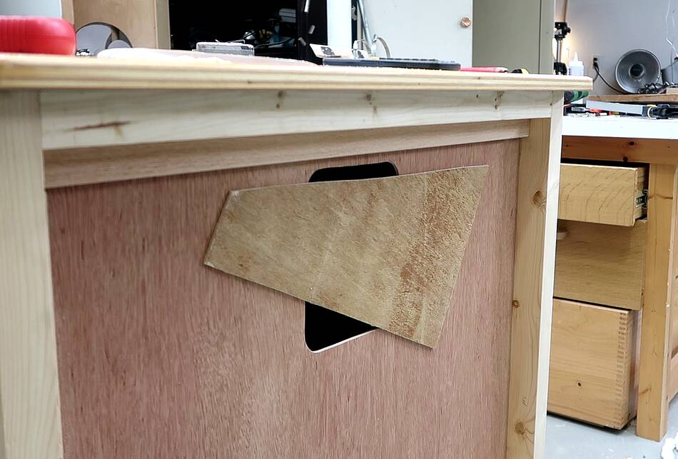 And the airflow was also high enough that with this piece of plywood
only partially covering the opening, there was still enough suction
to hold it in place. Even though a shopvac can produce more than
ten times the static pressure that my blower produces, its air
flow would be much lower, and with this much "hole" on the
front, there would not be enough vacuum to hold the piece of wood
in place.
And the airflow was also high enough that with this piece of plywood
only partially covering the opening, there was still enough suction
to hold it in place. Even though a shopvac can produce more than
ten times the static pressure that my blower produces, its air
flow would be much lower, and with this much "hole" on the
front, there would not be enough vacuum to hold the piece of wood
in place.
Next: Mounting the router and trying it out
 Blower for my dust collector v. 2 (2014)
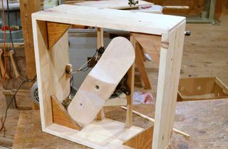 Building a box fan (2013)
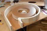 Blower design (2013)
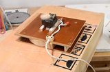 Mini dust collector
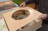 Air cleaner build (2016)
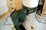 Cheap dust collector
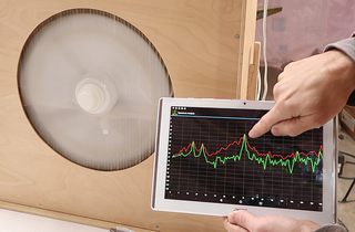 Measuring RPM with a spectrum analyzer app (video only, 2018)
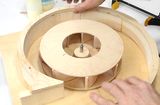 Blower impeller design experiments
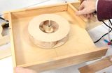 Blower housing shape experiments
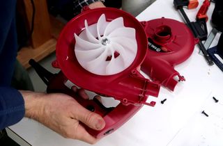 Miniature "leaf blower" experiments
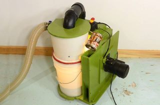 More about dust collection
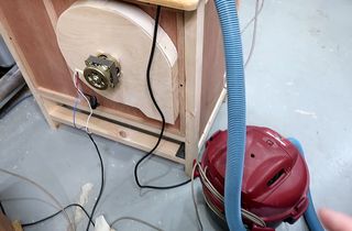 Why not just usee a shopvac for the router table?